Testing HONDA CR-V 1997 RD1-RD3 / 1.G Workshop Manual
[x] Cancel search | Manufacturer: HONDA, Model Year: 1997, Model line: CR-V, Model: HONDA CR-V 1997 RD1-RD3 / 1.GPages: 1395, PDF Size: 35.62 MB
Page 55 of 1395

Starting System
Starter Test
NOTE: The air temperature must be between 59 and'100'F (15 and 38"C) before testing.
Recommended Procedure:
. Use a staner system tester.
. Connect and operate the equipment in accordance
with the manufacturer's instructions.
. Test and troubleshoot as described.
Alte.nate Procedure:
. Use the following equipment:- Ammeter, 0 - 400 A- Voltmeter, 0 - 20 V (accurate within 0.1 volt)
Tachometer,0 - 1,200 rpm
. Hook up a voltmeter and ammeter as shown.
NOTE: After this test, or any subsequent repair. reset
the ECM/PCM to clear any codes (see section 1 1).
Check the Starter Engagement:
'1. Remove the No. 44 (15 A) fuse from the under-hood
fuse/relay box.
2. Turn the ignition switch to START (lll) with the shift
lever in E or E position (A/T) or with the clutch
pedal depressed {M/T). The starter should crank the
eng ine.
. lf the starter does not crank the engine, go to
step 3.
. lf it cranks the engine erratically or too slowly, go
to "Check for Wear and Damage" on the next
page.
NEGATIVE TERMINAL
4.
5.
6.
7.
8.
Check the battery, battery positive cable, ground.
staner cut relay, and the wire connections for loose-
ness and corrosion. Test again.
lf the staner still does not crank the engine, go to
step 4.
Unplug the connector (BLK /VHT wire and solenoid
terminal) from the starter.
Connect a jumper wire from the baftery positive (+)
terminal to the solenoid terminal.
The starter should crank the engine.
. lf the starter still does not crank the engine,
remove it, and diagnose its internal problem.
. lf the starter cranks the engine, go to step 6.
Check the ignition switch (see section 23).
Check the starter cut relay {see section 23}.
Check the IVT gear position switch (A/T) or the clutch
interlock switch (M[).
Check for an open in the wire between the ignition
switch and starter.
(cont'd)
4-5
www.emanualpro.com
Page 76 of 1395
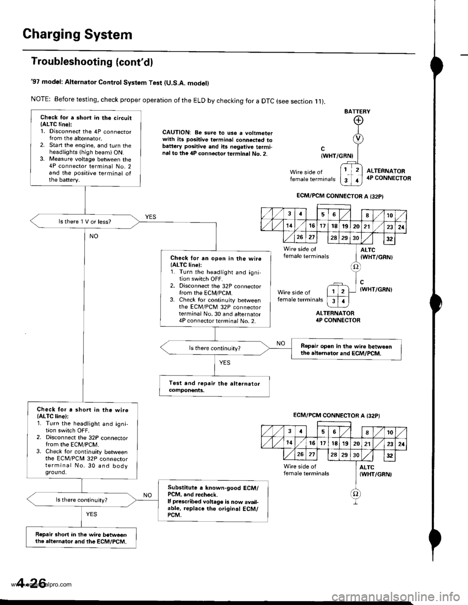
Charging System
Troubleshooting (cont'dl
'97 modol: Alternator Control System Test {U.S.A. model)
NOTE: Before testing, check proper operation ofthe ELD by checking for a DTC (see section .11).
CAUTION: Be sure to use a voltmeterwith ils positive terminal connected tobattery positive and hs negative termi-nalto the 4P connector terminal No. 2.
BATTERY
Wire side offemale terminals
{WHT/GRNI
ALTERNATORirP CONNECTOR
ALTEFNATOR4P CONNECTOR
Chock for a short in the circuitIALTC line):1. Disconnect the 4P connectorfrom the alternator.2. Start the engine, and turn theheadlights thigh beami ON.3. Me8sure voltage between the4P connector terminal No. 2and the positive terminal ofthe battery.
lstherelVorless?
Check for an open in the wire(ALTC linel:1. Turn the headlight and igni-tion switch OFF.2. Disconnect the 32P connectorfrom the ECN4/PCM.3. Check tor continuity betweenthe EcM/PcM 32P connectorterminal No.30 and alternator4P connector terminal No. 2-
Repair open in the wi.e betwoenthe atternator and ECM/PCM.ls there continuity?
Check for a shorl in the wiroIALTC line):1. Turn the headlight and ign;,I|on swrtcn UFF2. Disconnect the 32P connectorfrom the EcM/PcM.3. Check tor continuity betweenthe ECM/PCN4 32P connectorterminal No. 30 and bodyground.
Subslitute a known-good ECM/PCM, and recheck.It prescribed voha96 b now avail-able, replace the original ECM/PCM.
ls there continuity?
R€prir short in the wire betweenthe altornator and the ECM/PCM.
ECM/PCM CONNECTOR A I32PI
,/1./1810
./ l./t4161718t9202121
26272A293032
Wire side of ] ALTCfemale terminals I tWHT/cRNl
tlWHT/GRN)
female terminals
I
1
ECM/PCM CONNECTOR A {32P}
,/ ,/46810
,/1,/1416l7t8'1920212321
272A2S30:t2
Wire side of I ALTCfemale terminals {WHT/GRNI
f)
4-26
www.emanualpro.com
Page 77 of 1395
R'oR
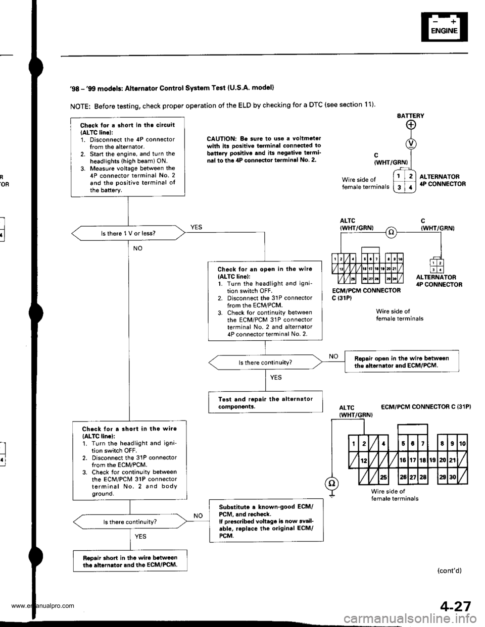
l
u
'98 -'9O modols: Alternator Contlol SYstem Te3t (U.S.A' model)
NOTE: Before testing, check proper operation of the ELD by checking for a DTC (see section 11)
EATTERY
CAUTION: Be surc to uso a voltmetorwith its oo3itive torminel connccted to
battery po3hivo tnd its negativo teami'
nal to the 4P connector torminal No 2.
ECM,/PCM CONNECTORc {31P)
Wire side olfemale terminals
cIWHT/GRN)
Wire side oltemale terminals
ALTERNATOR4P CONNECTOR
ALTC
IWHT/GBNI
ECM/PCM CONNECTOR C {31P}
(cont'd)
Chock tor . short in tha circuit
IALTC lino):1. Disconnoct the 4P connectorIrom the alternator.2. Start the engine, and turn the
headlights (high beam) ON.
3. Measure voltage between the4P connector terminal No. 2
and the positive terminal oIthe battsry.
lsthere 1V or less?
Check for an opon in the wire
IALTC line):1. Turn the headlight and igni-
tion switch OFF.2. Disconnect the 31P connectorfrom the ECM/PCM.3. Check tor continuity betweenth6 ECM/PCM 31P connectorterminal No. 2 and alternator4P connector terminal No. 2.
Ropair open in the wiro betweenthe ahornrtor and ECM/PCM.
Chack lor a rhort in tho wire
{ALTC lincl:'!. Turn the headlight and igni'tion switch OFF.2. Disconnect the 31P connectorIrom the ECM/PCM.3. Ch6ck for continuity betweenthe ECM/PCM 31P connectorterminal No. 2 and bodyground.
Substituto . known-good ECM/
PCM, .nd rochock.lf prdcdb€d voltage b now av.il-able, repl.ce the original ECM/
rcM.
Rcpair rhort in thc wire b.twconth. ahGrn.tol.nd the EcM/PcM.
4-27
www.emanualpro.com
Page 171 of 1395
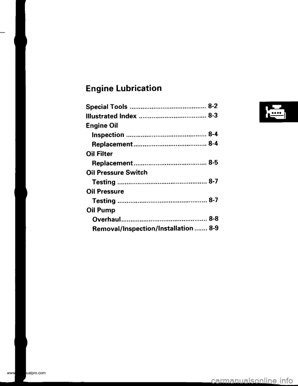
Engine Lubrication
Speciaf Tools .......... ...".""'8-2
lllustrated Index ........... .'...8-3
Engine Oil
Inspection ............'..'...'..' 8-4
Replacement ............................'........... 8-4
OilFilter
Rep1acement........................................ 8-5
Oil Pressure Switch
Testing ".....8-7
Oil Pressure
Testing ....'.' 8-7
OilPump
Overhaul..... ...........,......... 8-8
Removal/lnspection/lnstallation ....'.' 8-9
www.emanualpro.com
Page 177 of 1395
Oil Pressure SwitchOil Pressure
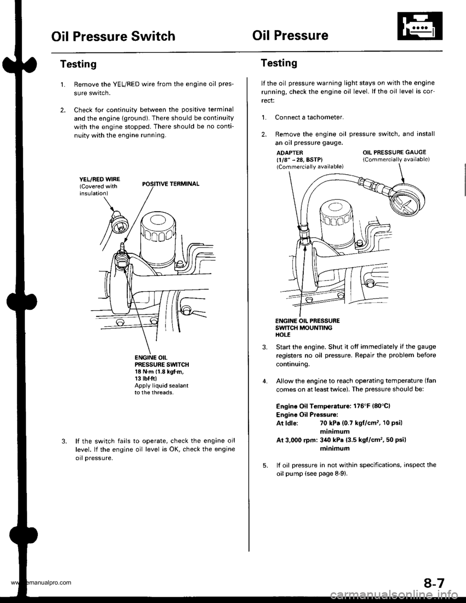
Testing
Remove the YEL/RED wire from the engine oil pres-
sure swrtcn.
Check for continuity between the positive terminal
and the engine {ground). There should be continuity
with the engine stopped. There should be no conti-
nuity with the engine running.
L
PRESSURE SWTCH18 N.m {1.8 kgf.m,13 tbr.ftlApply liquid sealantto the threads,
lf the switch fails
level. lf the engine
orl pressure.
to operate, check the engine oil
oil level is OK, check the engine
Testing
lf the oil pressure warning light stays on with the engine
running, check the engine oil level. lf the oil level is cor-
rect:
L Connect a tachometer.
2. Remove the engine oil
an oil pressure gauge.
ADAPTER(1/8" - 28, BSTP)(Commercially available)
pressure switch. and install
OIL PRESSURE GAUGE
{Commercially available)
4.
ENGINE OIL PRESSURESWTTCH MOUNNNGHOt-E
Start the engine. Shut it off immedjately if the gauge
registers no oil pressure. Repair the problem before
continuing.
Allow the engine to reach operating temperature (fan
comes on at least twice). The pressure should be:
Engino Oil Temperature: 176'F (80'C)
Engine Oil Pressure:
At ldle:70 kPa (0.7 kgt/cm'�, 10 psil
minimum
Ai 3,000 rpm: 3/r0 kPa {3.5 kgt/cm', 50 psi)
minimum
lf oil pressure in not within specifications, inspect the
oil pump (see page 8-9).
8-7
www.emanualpro.com
Page 189 of 1395
Cooling
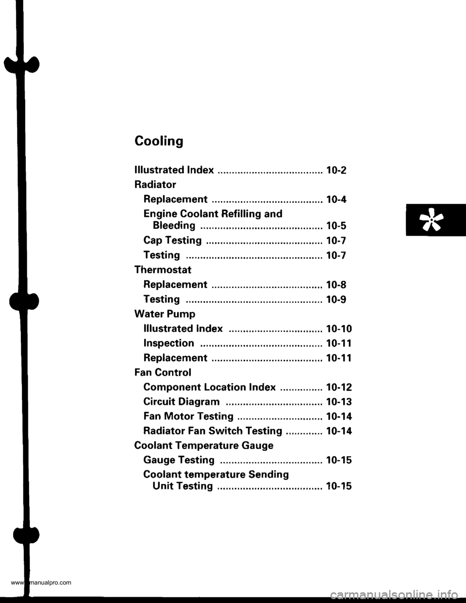
f ffustrated Index ........... ..... 1O-2
Radiator
Rep|acement ...........,....,...................... 10-4
Engine Coolant Refilling and
Bleeding ..,.,................. 10-5
Cap Testing .................... 10-7
Testing ......10-7
Thermostat
Rep|acement ....................................... 10-8
Testing ...... 10-9
Water Pump
lllustrated lndex ....,..... .. 10-10
Inspection . 10-1 1
Replacement ....................................,.. 10-1 1
Fan Gontrol
Component Location Index ............... 10-12
Circuit Diagram ............. 10-13
Fan Motor Testing ......... 10-14
Radiator Fan Switch Testing ............. 10-14
Coolant Temperature Gauge
Gauge Testing ............... 10-15
Coolant temperature Sending
Unit Testing ........,....... 10-15
www.emanualpro.com
Page 195 of 1395
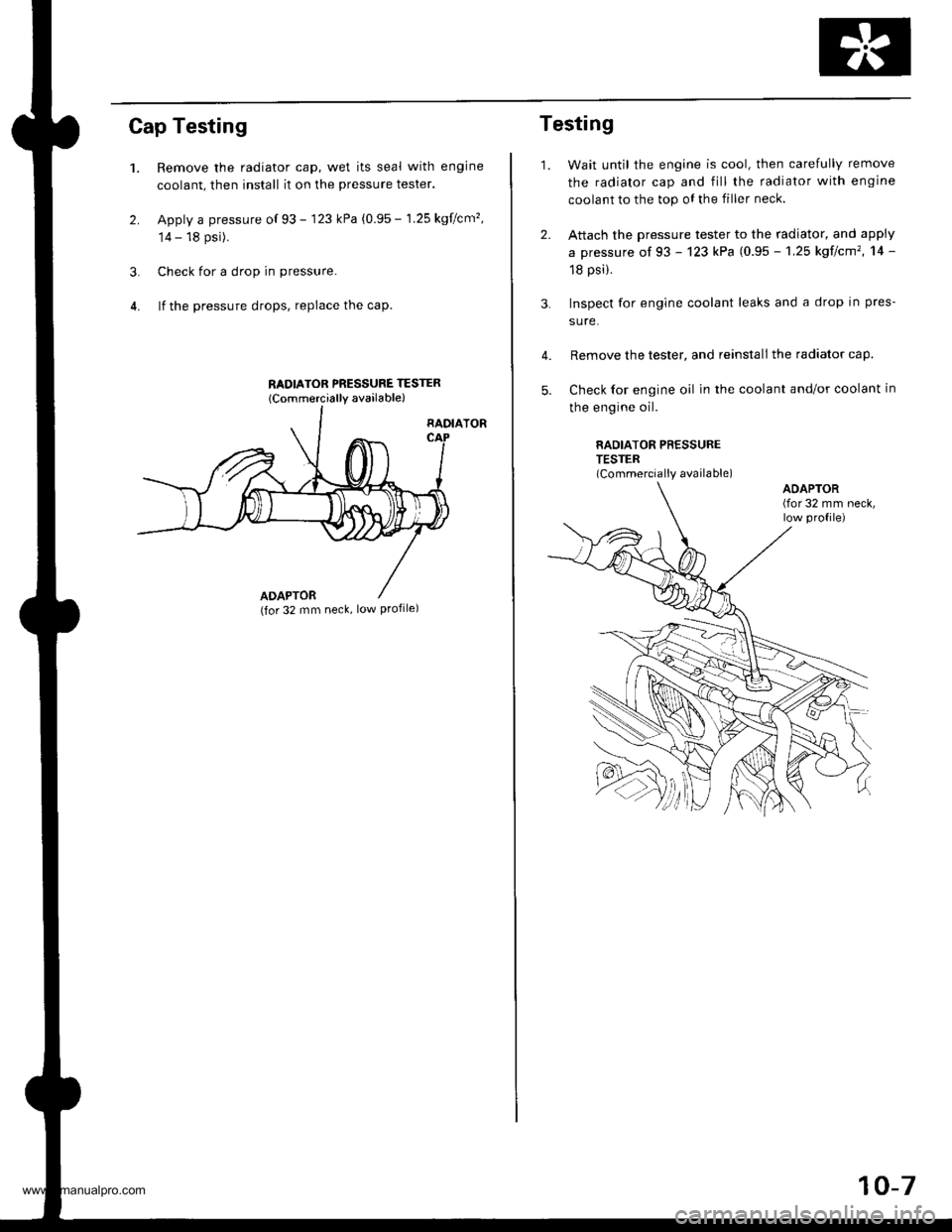
Cap Testing
1.
2.
Remove the radiator cap, wet its seal with engine
coolant, then install it on the pressure tester.
Apply a pressure of 93 - 123 kPa (0.95 - 1.25 kgflcm'�,
14 - 18 psi).
Check for a drop in pressure.
lf the pressure drops, repiace the cap.
RADIATOR PNESSURE TESTER
lCommercially available)
3.
RADIATOR
ADAPTOR(for 32 mm neck, low Profile)
2.
3.
Testing
1.Wait until the engine is cool, then carefully remove
the radiator cap and fill the radiator with engine
coolant to the top oI the filler neck.
Attach the pressure tester to the radiator, and apply
a pressure of 93 - 123 kPa (0.95 - 1,25 kgf/cm'�, 14 -
18 psi).
Inspect for engine coolant leaks and a drop in pres-
sure.
Remove the tester, and reinstall the radiator cap.
Check for engine oil in the coolant and/or coolant in
the engine oil.
RAOIATOR PRESSURETESTER(Commercially available)
4.
5.
ADAPTOR(for 32 mm neck,low profile)
10-7
www.emanualpro.com
Page 197 of 1395
Testing
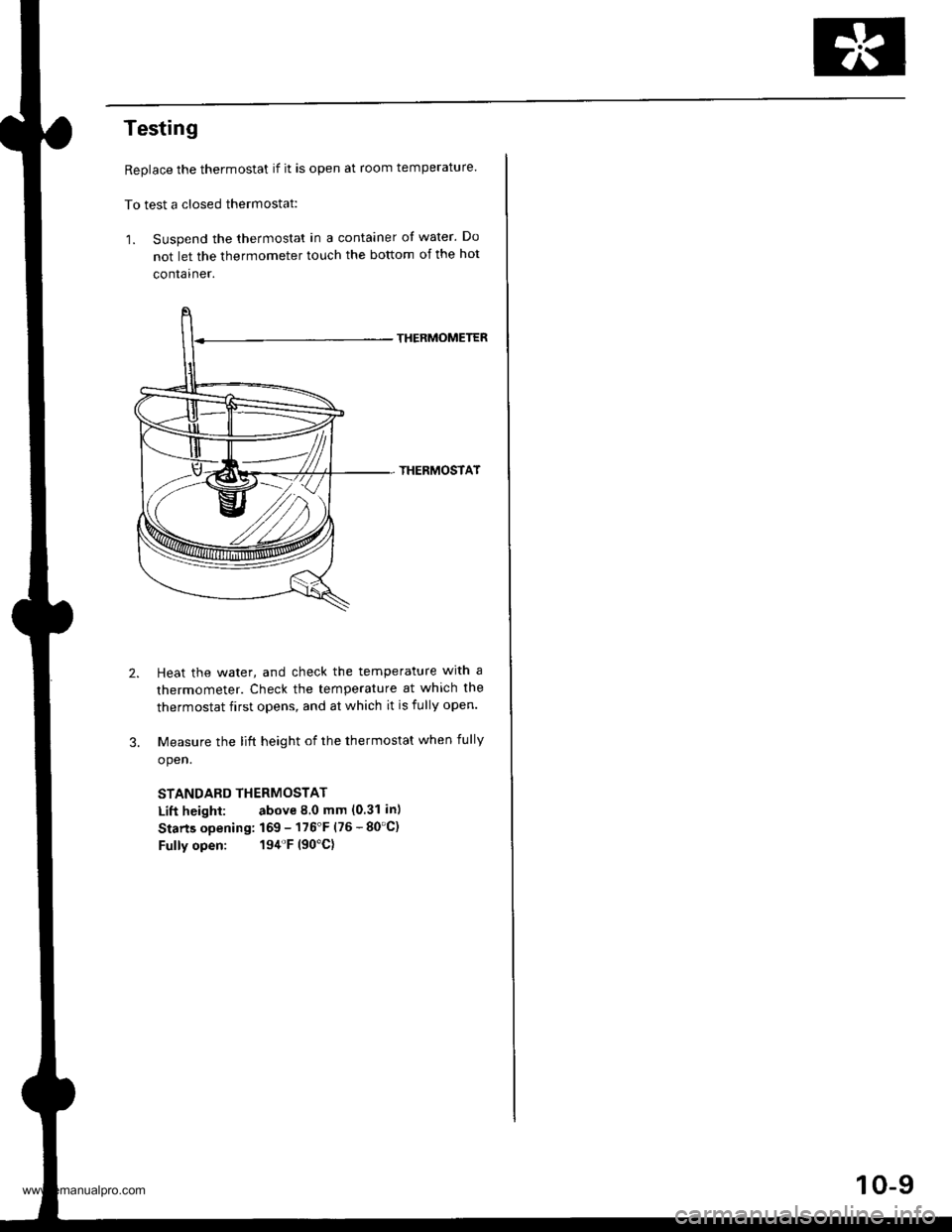
Replace the thermostat if it is open at room temperature.
To test a closed thermostat:
1. Suspend the thermostat in a container of water. Do
not let the thermometer touch the bottom of the hot
container.
THERMOMETER
THERMOSTAT
Heat the water, and check the temperature with a
thermometer. Check the temperature at which the
thermostat first opens, and at which it is fully open.
Measure the lift height of the thermostat when fully
open.
STANDARD THERMOSTAT
Lift height: above 8.0 mm (0.31 in)
Starts opening: 169 - 176'F (76 - 80'C)
Fully open: 194'F (90'C)
10-9
www.emanualpro.com
Page 202 of 1395
Fan Control
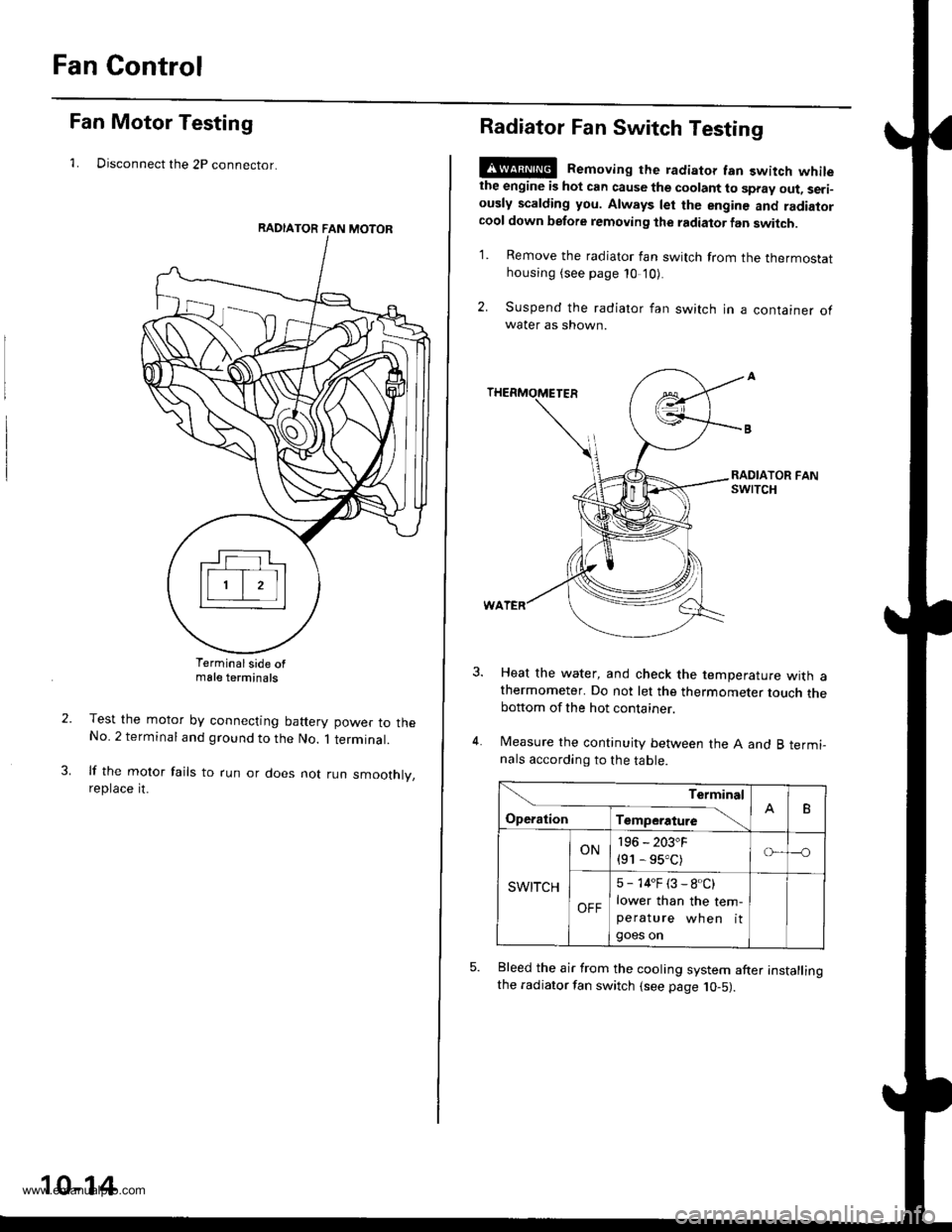
Fan Motor Testing
1. Disconnect the 2P connector.
Terminalside ofmale terminals
Test the motor by connecting battery power to theNo. 2 terminal and ground to the No. 1 terminal.
lf the motor fails to run or does not run smoothly,reptace rt.
RADIATOR FAN MOTOR
10-14
Radiator Fan Switch Testing
E@ Removing the radiator fan switch whilethe engine is hot can cause the coolant to spray out, seri-ously scalding you. Always let the enginc and radiatorcool down before removing the radiator fan switch.
1. Remove the radiator fan switch from the thermostathousing (see page 10 '10).
2. Suspend the radiator fan switch in a container ofwater as shown.
Heat the water, and check the temperature with athermometer. Do not let the thermometer touch thebottom of the hot container.
Measure the continuity between the A and B termi-nals according to the table.
Bleed the air from the cooling system after installingthe radiator fan switch (see page 10-5).
Terminal
op".*i- Tr"ip".a*" \.B
SWITCH
ON196 - 203"F
{91 - 95.C)o---o
OFF
5 - 14"F (3 - 8.C)
lower than the tem-peratu re wh en itgoes on
www.emanualpro.com
Page 203 of 1395
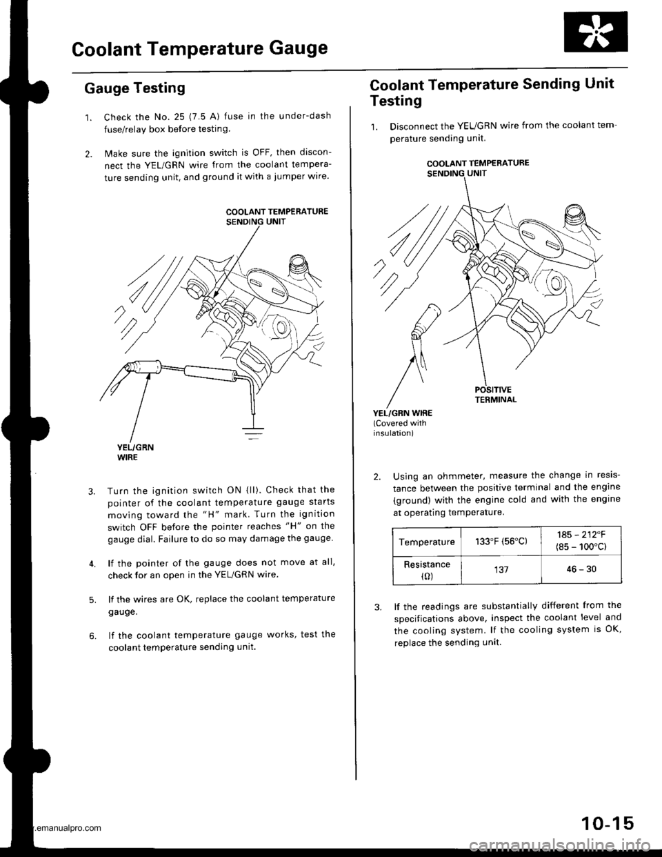
Goolant Temperature Gauge
Gauge Testing
1. Check the No. 25 (7.5 A) fuse in the under-dash
fuse/relay box before testin9.
2. Make sure the ignition switch is OFF, then discon-
nect the YEL/GRN wire from the coolant tempera-
ture sending unit. and ground it with a jumper wire.
YEL/GRNWIRE
Turn the ignition switch ON {ll). Check that the
pointer of the coolant temperature gauge starts
moving toward the "H" mark. Turn the ignition
switch OFF before the pointer reaches "H" on the
gauge dial. Failure to do so may damage the gauge.
lf the pointer of the gauge does not move at all,
check for an open in the YEL/GRN wire.
lf the wires are OK, replace the coolant temperature
gauge.
lf the coolant temperature gauge works, test the
coolant temperature sending unit.
5.
COOLANT TEMPERATURE
Coolant Temperature Sending Unit
Testing
1. Disconnect the YEUGRN wire from the coolant tem
perature sending unit.
COOLANT TEMPERATURE
POSITIVETERMINAL
YEL/GRN WIRE(Covered withinsulation)
2. Using an ohmmeter, measure the change in resis-
tance between the positive terminal and the engine
(ground) with the engine cold and with the engine
at operating temPerature.
Temperature133.F (56'C)1A5 - 212F
(8s - 100'c)
Resistance(0)13746-30
3. lf the readings are substantially different from the
specitications above, inspect the coolant level and
the cooling system. lf the cooling system is OK,
replace the sending unit.
10-15
www.emanualpro.com