battery terminals HONDA CR-V 1997 RD1-RD3 / 1.G Workshop Manual
[x] Cancel search | Manufacturer: HONDA, Model Year: 1997, Model line: CR-V, Model: HONDA CR-V 1997 RD1-RD3 / 1.GPages: 1395, PDF Size: 35.62 MB
Page 41 of 1395

Lubrication Points
For the details of lubrication points and type of lubricants to be applied. refer to the illustrated index and various work pro-
cedures (such as Assembly/Reassembly, Replacement, Overhaul, Installation, etc.) contained in each section.
Recomm6nded Engine OilEngine oil viscosity for ambient temperature ranges
100'F
-30 -20 .10 0 10 20 30 40'c
r1: Always use Genuine Honda Manual Transmission Fluid {MTF). Using motor oil can cause stiffer shifting because it
does not contain the orooer additives.*2: Always use Genuine Honda Premium Formula Automatic Transmission Fluid (ATF). Using a non-Honda ATF can affect
shift qualitv.+3r Always use Genuine Honda DOT 3 Brake Fluid. Using a non-Honda brake fluid can cause corrosion and decrease the
life of the system.*4: Always use Genuine Honda Power Steering Fluid. Using any other type of power steering fluid or automatic transmis-
sion fluid can caused increased wear and poor steering in cold weather.
API SERVICE LABEL
/,.*-G\
/.'z-\e\t/6AE\ll-;-1 5w-30 /---l
w
API CERTIFICATION SEAL
ffi-20 0 20
NO.LUBRICATION POINTSLUBRICANT
EngineAPI Service Grade: Use SJ "Energy Conserving" grade oil. The oilcontainer may also display the API Certitication seal shownbelow. Make sure it says "For Gasoline Engines." SAE vjscosity:See chart below.
2
TransmissionManualGenuine Honda MTF*1
AutomaticGenuine Honda Premium Formula Automatic Transmission Fluid(ATF)*'
3Rear differentialGenuine Honda CVT Fluid
4Brake line (includes ABS line)Genuine Honda DOT 3 Brake Fluid*3
5Clutch LineBrake fluid DOT 3 or DOT 4*3
6Shift lever pivots (Manual transmission)Grease with molybdenum disultide
1Release fork (Manual transmission)LJrea Grease UM264 P/N 4'1211 - PYs - 305
IPower steering gearboxSteering grease P/N 08733 - B070E
Throttle cable end {Dashboard lower panel holelSilicone grease
10l112
14
Throttle cable end (Throttle link)Brake master cylinder pushrodPedal linkageBattery terminalsFuelfill lidClutch master cylinder pushrod
Multi purpose grease
1617181920
Hood hinges and hood lockTailgate hingesHatch glass hingesDoor hinges, upper and lowerDoor opening detent
Honda White Lithium Grease
21
22
Caliper Piston seal, Dust seal,Caliper pin, PistonShilt cable and select cable {Manual transmission)Silicone grease
23Brake line ioints (Front and rear wheelhouse)Rust preventives
24Power steering systemGenuine Honda Power Steering Fluid-.
25Air conditioning compressorCompressor oil: SP 10 lP/N 38897 - P13 - A0lAH or38899-P13-A01)For Refrigerant: HFC 134a (R,134a)
3-2
www.emanualpro.com
Page 56 of 1395
Starting System
Starter Test (cont'dl
Check lor Wear and D8mage
The starter should crank the engine smoothly and
steadily. lf the staner engages, but cranks the engine
erratically, remove it, and inspect the starter drive gear
and torque converter ring gear or flywheel ring gear for
oamage.
Check the drive gear overrunning clutch for binding or
slipping when the armature is rotated with the drive
gear held. lf damaged, replace the gears.
Check Cranking Voltage and Current Draw
Cranking voltage should be no less than 8.7 volts on Ay'T
models, and 8.0 volts on M/T moders.
Current draw should be no more than 230 amperes on
A,/T models, and 200 amperes on M/T models.
lf cranking voltage is too low, or current draw too high,
check for:
. dead or low battery.
a open circuit in starter armature commutator seg,
ments.
. starter armature dragging.
. shorted armature winding.
. excessive drag in engine.
Check Cranking rpm
Engine speed during cranking should be above 100 rpm.
lf speed is too low, check for:
a loose baftery or starter terminals.
. excesslvely worn staner brushes
. open circuit in commutator segments.
. dirty or damaged helical splines or drive gear.
a defective drive gear overrunning clutch.
Check Starter Disengagement
With the shift lever in @ or @ position (A,iT) or with the
clutch pedal depressed {M/T). turn the ignition switch to
START (lll). and release to ON (ll).
The starter drive gear should disengage from the torque
converter ring gear or flywheel ring gear when you
release the key.
lf the drive gear hangs up on the torque converter ring
gear or flywheel ring gear, check for
. solenoid plunger and switch malfunction.
. dirty drive gear assembly or damaged overrunning
clutch.
Starter Solenoid Test
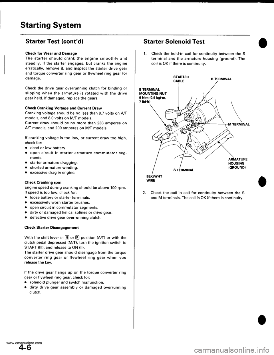
1. Check the hold-in coil for continuity between the S
terminal and lhe armature housing (ground). The
coil is OK if there is continuity.
STARTER
B TERMINALMOUNTING NUT9 N.m 10.9 kgtm,7 tbtftl
TERMINAL
ARMATUREHOUSING(GROUND}
BLK/WHTWIRE
Check the pull in coil for continuity between the S
and M terminals. The coil is OK if there is continuity.
2.
4-6
www.emanualpro.com
Page 74 of 1395
Gharging System
Troubleshooting
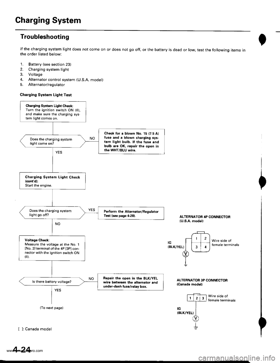
lf the charging system light does not come on or does not go off, or the battery is dead or low, test the following items inthe order listed below:
1. Battery (see section 23)
2. Charging system light
3. Voltage
4. Alternator control system (U.S.A. model)
5. Alternator/regulator
Charging System Light Test
ALTERNATOR 4P CONNECTOR{U.S,A. modell
(BLK/YEL)
2
3
Wire sade offemale terminals
I
I
I
ALTERNATOR 3P CONNECTORlCaneda model'
Iemale terminals
[ ]: Canada model
Chsrging Systom Light Check:Turn the ignition switch ON {ll),and make sure the charging system light comes on.
Check for a blown No. 15 17.5 Alfuse and a blown charging sys-tem light bulb. lf the tusa .ndbulb are OK, repair th€ open inth€ WHT/BLU wire.
Does the charging systemlight come on?
Charging System Light Check{com'd}:Start the engine.
Does the charging systemlight go offfPerform the Alte.nator/RegulatorTest lsee page +281.
Voltage Check:Measure the voltage at the No. IlNo. 2iterminal of the 4P [3Plcon-nector with the ignition switch ON{ ).
Ropair the open in the BLK/YELwiae betwoen the altemator andunder-da3h luso/relay box.
ls there battery voltage?
(To next page)
4-24
www.emanualpro.com
Page 76 of 1395
Charging System
Troubleshooting (cont'dl
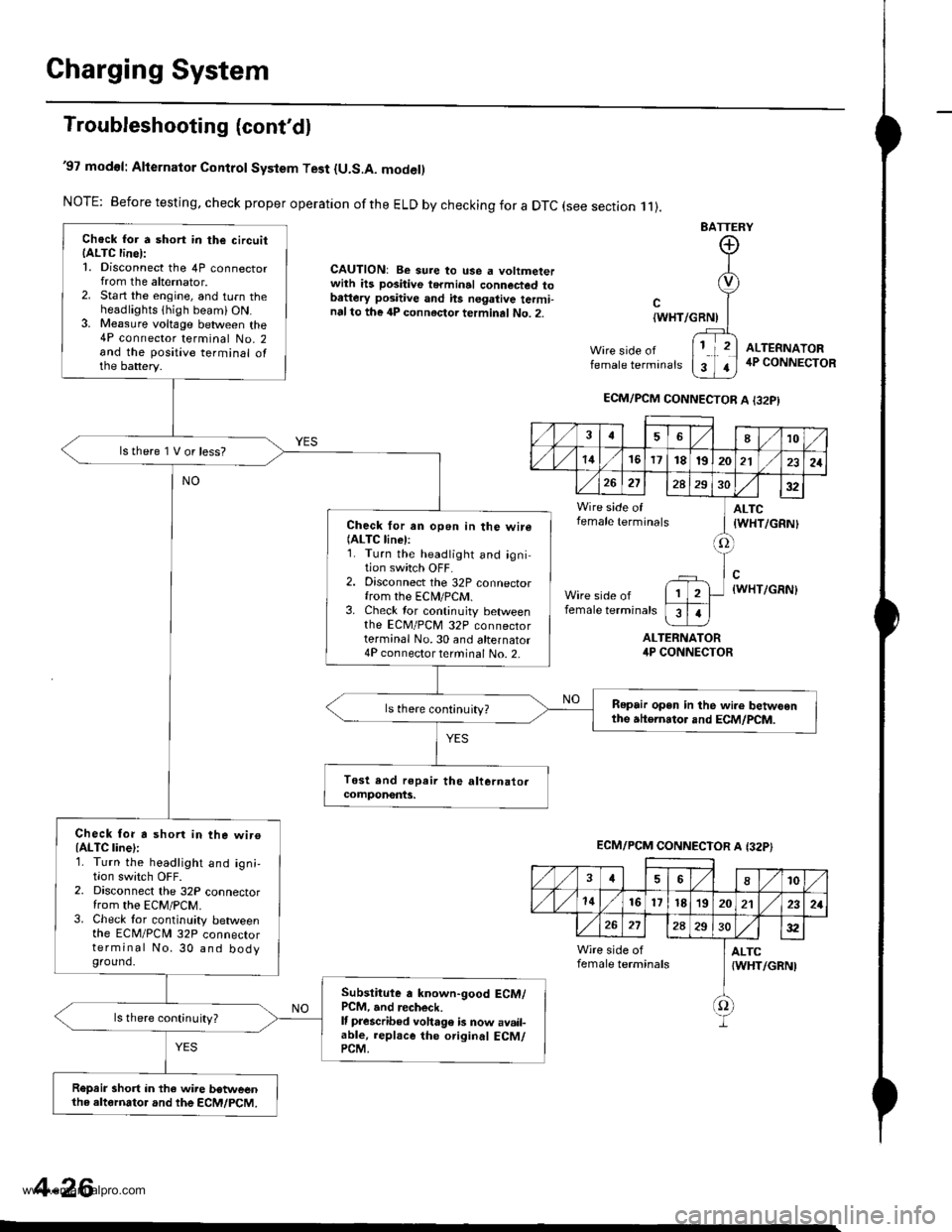
'97 modol: Alternator Control System Test {U.S.A. model)
NOTE: Before testing, check proper operation ofthe ELD by checking for a DTC (see section .11).
CAUTION: Be sure to use a voltmeterwith ils positive terminal connected tobattery positive and hs negative termi-nalto the 4P connector terminal No. 2.
BATTERY
Wire side offemale terminals
{WHT/GRNI
ALTERNATORirP CONNECTOR
ALTEFNATOR4P CONNECTOR
Chock for a short in the circuitIALTC line):1. Disconnect the 4P connectorfrom the alternator.2. Start the engine, and turn theheadlights thigh beami ON.3. Me8sure voltage between the4P connector terminal No. 2and the positive terminal ofthe battery.
lstherelVorless?
Check for an open in the wire(ALTC linel:1. Turn the headlight and igni-tion switch OFF.2. Disconnect the 32P connectorfrom the ECN4/PCM.3. Check tor continuity betweenthe EcM/PcM 32P connectorterminal No.30 and alternator4P connector terminal No. 2-
Repair open in the wi.e betwoenthe atternator and ECM/PCM.ls there continuity?
Check for a shorl in the wiroIALTC line):1. Turn the headlight and ign;,I|on swrtcn UFF2. Disconnect the 32P connectorfrom the EcM/PcM.3. Check tor continuity betweenthe ECM/PCN4 32P connectorterminal No. 30 and bodyground.
Subslitute a known-good ECM/PCM, and recheck.It prescribed voha96 b now avail-able, replace the original ECM/PCM.
ls there continuity?
R€prir short in the wire betweenthe altornator and the ECM/PCM.
ECM/PCM CONNECTOR A I32PI
,/1./1810
./ l./t4161718t9202121
26272A293032
Wire side of ] ALTCfemale terminals I tWHT/cRNl
tlWHT/GRN)
female terminals
I
1
ECM/PCM CONNECTOR A {32P}
,/ ,/46810
,/1,/1416l7t8'1920212321
272A2S30:t2
Wire side of I ALTCfemale terminals {WHT/GRNI
f)
4-26
www.emanualpro.com
Page 77 of 1395
R'oR
l
u
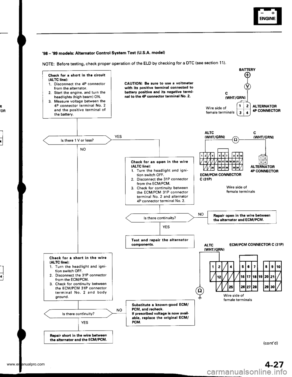
'98 -'9O modols: Alternator Contlol SYstem Te3t (U.S.A' model)
NOTE: Before testing, check proper operation of the ELD by checking for a DTC (see section 11)
EATTERY
CAUTION: Be surc to uso a voltmetorwith its oo3itive torminel connccted to
battery po3hivo tnd its negativo teami'
nal to the 4P connector torminal No 2.
ECM,/PCM CONNECTORc {31P)
Wire side olfemale terminals
cIWHT/GRN)
Wire side oltemale terminals
ALTERNATOR4P CONNECTOR
ALTC
IWHT/GBNI
ECM/PCM CONNECTOR C {31P}
(cont'd)
Chock tor . short in tha circuit
IALTC lino):1. Disconnoct the 4P connectorIrom the alternator.2. Start the engine, and turn the
headlights (high beam) ON.
3. Measure voltage between the4P connector terminal No. 2
and the positive terminal oIthe battsry.
lsthere 1V or less?
Check for an opon in the wire
IALTC line):1. Turn the headlight and igni-
tion switch OFF.2. Disconnect the 31P connectorfrom the ECM/PCM.3. Check tor continuity betweenth6 ECM/PCM 31P connectorterminal No. 2 and alternator4P connector terminal No. 2.
Ropair open in the wiro betweenthe ahornrtor and ECM/PCM.
Chack lor a rhort in tho wire
{ALTC lincl:'!. Turn the headlight and igni'tion switch OFF.2. Disconnect the 31P connectorIrom the ECM/PCM.3. Ch6ck for continuity betweenthe ECM/PCM 31P connectorterminal No. 2 and bodyground.
Substituto . known-good ECM/
PCM, .nd rochock.lf prdcdb€d voltage b now av.il-able, repl.ce the original ECM/
rcM.
Rcpair rhort in thc wire b.twconth. ahGrn.tol.nd the EcM/PcM.
4-27
www.emanualpro.com
Page 89 of 1395

Disconnest the lilP connector from the control unit.
Csvity WireTest condition
R€conn€ct tho 14P connGctor to the control unit.
Test: Desired resultPossible cause it result is not obtained
BRNAr'VHTUnder all conditionsCheck for resistance to groundl
There should be 80 - 120 o.
Faulty actuator solenoid
Poor ground (G202)
An open in the wire1BRNUnder all conditionsCheck for resistance to groundl
There should be 40 - 60 0.
11BRN/BLKUnder all conditionsCheck for resistance to ground:
There should be 70 - 110 O.
2GRY
lgnition switch ON (ll),
main switch ON and
brake pedal depressed,
then released
Check for voltage to ground:
There should be 0 V with the pedal
depressed and battery voltage with
the pedal released.
. Faulty brake switch. An open in the wire
BLKUnder all conditionsCheck for continuity to ground:
There should be continuity.
. Poor ground (G401). An open in the wire
5GRNMHT
Brake pedal depressed,
then released
Check for voltage to ground:
There should be battery voltage with
the pedal depressed, and 0 V with
the pedal released.
Blown No.52 1'15 Alfuse in the
under-hood fuse/relay box
Faulty brake switch
An open in the wire
LT GRN/
RED
Set button pushedCheck for voltage to ground:
There should be battery voltage.Blown No. 52 {'15 A} fuse in the
under-hood fuse/relay box
Faulty horn relay
Faulty sevresume switch
Faulty cable reel
An open in the wire7LT GRN/
BLK
Resume button pushed
10RED/BLU
lgnition switch ON lll)Attach to ground:
Cruise indicator light in the gauge
assembly should come on.
Elown bulbBlown No. 25 (7.5 A) tuse in theunder-dash fuse/relay box
Faulty dimming circuit in the gauge
assembly
An open in the wire
ELU^r'r'HT
lgnitjon switch ON {ll}and main switch ON;
raise the front of the
vehicle, block one wheel
and rotate the other
wheel slowly.
Check for voltage between the
ELUA/VHT @ and BLK O terminalsl
There should be 0 - 5 V or more-0 - 5 V or more repeatedly.
Faulty vehicle speed sensor (VSS)
An open in the wire
r3LT GRN
lgnition switch ON {ll}and main switch ONCheck for voltage to ground:
There should be battery voltage.
Blown No. 14 (7.5 A) fuse in theunder-dash fuse/relay box
Faulty main switch
An open in the wire
l4PNK
A'/T: Shift lever in E, EotE
lvl/T: Clutch pedal
releaseo
Check for continuity to ground:
There should be continuity.NOTE: There should be no continu-
ity when the shift lever is in otherpositions or when the clutch pedal is
oepresseo.
Faulty A/f gear position switch 1A,/TlFaulty or misadjusted clutch switch
fi{/r)Poor ground (G101)
An open in the wire
BLU
Start tho engine. turnthe main switch ON, anddrive the vehicle over 25
mph (40 km/h)with the
crurse control set
Check for voltage to ground:
There should be approx.5 V
. Faulty cruise control unit. Shod to ground
*: '98 - 00 models with Automatic Transmission.
4-39
www.emanualpro.com
Page 91 of 1395
n-
n-
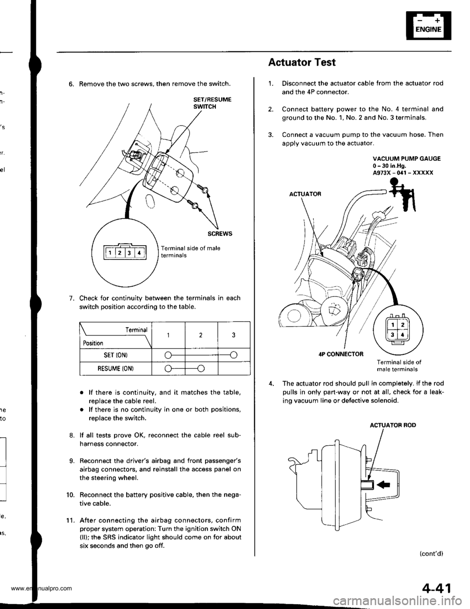
6. Remove the two screws. then remove the switch.
Check for continuity between the terminals in each
switch position according to the table.
. lf there is continuity, and it matches the table,
replace the cable reel.
. lf there is no continuity in one or both positions,
replace the switch.
lf all tests prove OK, reconnect the cable reel sub-
harness connector.
Reconnect the driver's airbag and front passenger's
airbag connectors, and reinstall the access panel on
the steering wheel.
Reconnect the battery positive cable. then the nega-
tive cable.
After connecting the airbag connectors, confirm
proper system operation: Turn the ignition switch ON
(ll); the SRS indicator light should come on for about
six seconds and then go off.
,s
r.
1e
to
7.
l
9.
10.
SET/RESUME
Terminal
t*,r*
-__\l23
SET ION)o----o
RESUME (ON)o----o
11.
4-41
1.
Actuator Test
Disconnect the actuator cable trom the actuator rod
and the 4P connector.
Connect battery power to the No. 4 terminal and
ground to the No. 1, No. 2 and No. 3 terminals,
Connect a vacuum pump to the vacuum hose. Then
apply vacuum to the actuator.
VACUUM PUMP GAUGE0-30 in.Hg.A973X-041-XXXXX
Terminalside otmale terminals
The actuator rod should pull in completely. lf the rod
pulls in only part-way or not at all, check for a leak-
ing vacuum Iine or defective solenoid.
ACTUATOB ROD
(cont'd)
www.emanualpro.com
Page 112 of 1395
Engine Removal/lnstallo cton
Installation (cont'd)
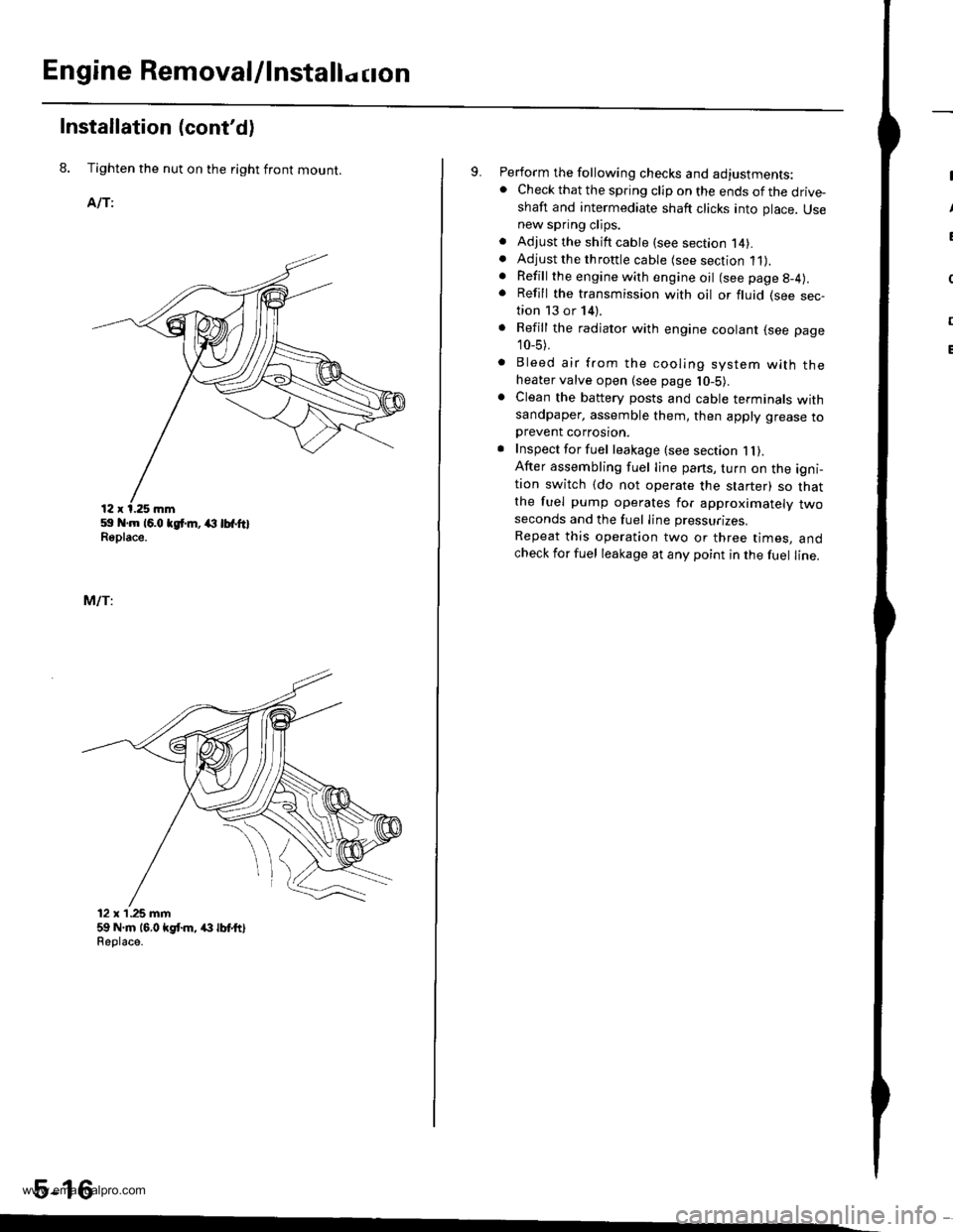
8. Tighten the nut on the right front mount.
AlTi
59 .m 16.0 tgt m, (l lbfftlReplace.
MlTi
12 x'1.25 mm59 N.m 16,0 kgt m, /(} lbt ttlReolace.
5-16
9. Perform the following checks and adjustments:. Check that the spring clip on the ends of the drive-shaft and intermediate shaft clicks into place. Usenew spring clips.. Adjust the shift cable (see section l4).. Adjust the throttle cable (see section 11).. Refill the engine with engine oil (see page g-4).
. Refill the transmission with oil or fluid (see sec-tion 13 or 14).
. Refill the radiator with engine coolant (see page
10_5).
. Bleed air from the cooling system with theheater valve open (see page l0-5).. Clean the battery posts and cable terminals withsandpaper, assemble them, then apply grease toDrevent corrosron.. Inspect for fuel leakage (see section 1l).After assembling fuel line pans, turn on the igni-tion switch (do not operate the starter) so thatthe fuel pump operates for approximately twoseconds and the fuel Iine pressurizes.
Repeat this operation two or three times, andcheck for fuel leakage at any point in the fuel line.
www.emanualpro.com
Page 202 of 1395
Fan Control
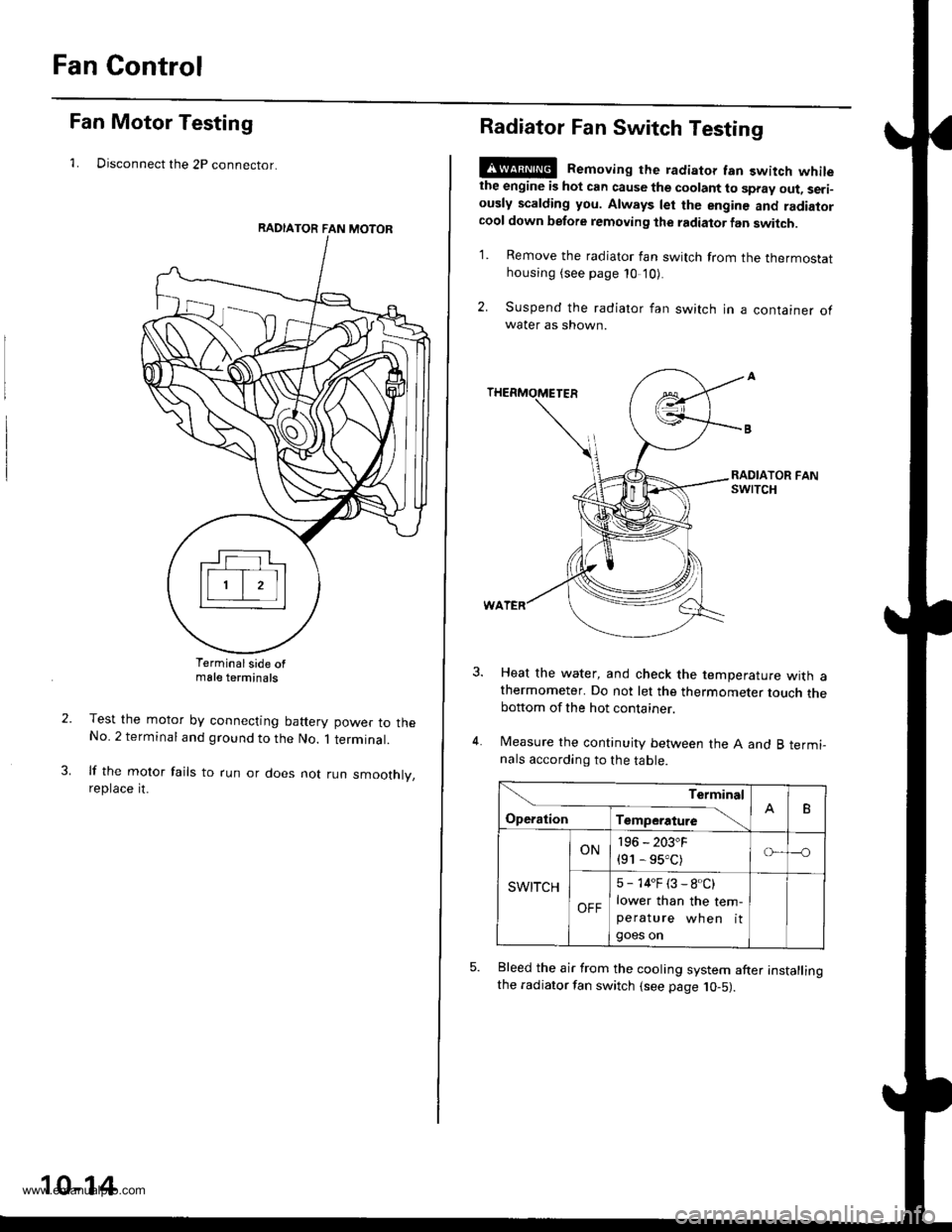
Fan Motor Testing
1. Disconnect the 2P connector.
Terminalside ofmale terminals
Test the motor by connecting battery power to theNo. 2 terminal and ground to the No. 1 terminal.
lf the motor fails to run or does not run smoothly,reptace rt.
RADIATOR FAN MOTOR
10-14
Radiator Fan Switch Testing
E@ Removing the radiator fan switch whilethe engine is hot can cause the coolant to spray out, seri-ously scalding you. Always let the enginc and radiatorcool down before removing the radiator fan switch.
1. Remove the radiator fan switch from the thermostathousing (see page 10 '10).
2. Suspend the radiator fan switch in a container ofwater as shown.
Heat the water, and check the temperature with athermometer. Do not let the thermometer touch thebottom of the hot container.
Measure the continuity between the A and B termi-nals according to the table.
Bleed the air from the cooling system after installingthe radiator fan switch (see page 10-5).
Terminal
op".*i- Tr"ip".a*" \.B
SWITCH
ON196 - 203"F
{91 - 95.C)o---o
OFF
5 - 14"F (3 - 8.C)
lower than the tem-peratu re wh en itgoes on
www.emanualpro.com
Page 269 of 1395

Powertrain Control Module Terminal Arrangement -'97 Model
FCM CONNECTOR A (32P)NOTE: Standard battery voltage is 12 V.
Wire side of lemale terminals
f€rminalnumlreJWirecolor
Telminalnama
DescriptionSignal
YELlNJ4 (No.4 FUELINJECTOR)Drives No. 4 {uel injector.With engine running: duty controlled
2BLUlNJ3 (No.3 FUELINJECTOR)Drives No. 3luel injector.
REDlNJ2 {No.2 FUELINJECTOR)Drives No.2 tuel injector.
BRNlNJl (No. l FUELINJECTOR)Drives No. 1 fuel injector.
5BLK WHTSO2SHIC (SECONDARY
HEATED OXYGEN SENSOR HEATER CONTROL)
D ves secondary heated oxygensensor heater.With ignition switch ON {ll): battery voltageWith fully warmed up engino running: dutycontrolled
6BLKAr'YHT
PO2SHTC (PRIMARY
HEATED OXYGENSENSOR HEATERCONTROL}
Drives primary heated oxygensensor heater,With ignition switch ON lll): battery voltagewith fully warmed up engine running: dutycontroll6d
I8RN/BLKLGl (LOGIC GROUND}Ground forthe PCM control circuit.Less than 1.0 V at all times
10BLKPG1 lPOWER GROUND}Ground for the PCM power circuit.
l1YEUELKIGPl lPOWER SOURCE}Power source for the PCM controlcircuit.
With ignition switch ON (ll): battery voltageWith ignition switch OFF: 0 V
12BLI(BLUIACV {IDLE AIRCONTROL VALVE}Drives IACV.With €ngine running: duty controlled
REDryEL
PCS (EVAP PURGECONTFOL SOLENOIDVALVE)
Drives EVAP purge controlsolenoid valve.
With engine running, engine coolantbelow 154'F (68"C): battery voltageWith engine running, engine coolantabove 154"F (68"C): duty controlled
16GRN/VELFLR (FUEL PUMP RELAY)Drives Iuel pump relay.0 V for two seconds after turning ignition
switch ON lll), then battery voltage
118LI(REDACC (A,/C CLUTCHRELAY}Drives Ay'C clutch relay.With comoressor ON: 0 VWith compressor OFF: baftery voltage
18GRN/ORNMIL (MALFUNCTION
INDICATOR LAMP}Drives MlL.With MIL turned ON: 0 VWith MIL turned OFF: baftery voltage
19*WHT/GRNALTC (ALTERNATOR
CONTROL}Sends alternator control signal.With tully warmed-up engine running:
battery voltageDuring driving with smallelectrical load:0 '
20YEUGRNICM (IGNITION CONTROLMODULE)Sends ignition pulse.With ignition switch ON (ll): baftery voltageWith engine running: pulses
22BRN/BLKLG2 (LOGIC GROUND}Ground tor the PCM control circuit.Less than 1.0 V at alltimes
23BLKPG2 {POWER GROUND}Ground lor the PCM power circuit.
24YEUBLKIGP2 {POWER SOURCE}Power source for the PCM controlcircuit.
With ignition switch ON (ll): battery voltage
With engine switch OFF: 0 V
27GRNFANC (RADIATOR FANCONTROL)Drives radiator {an relay.With radiator fan running: 0 VWith radiator fan stopped: baftery voltage
*: USA
{cont'd)
11-67
www.emanualpro.com