Mil HONDA CR-V 1998 RD1-RD3 / 1.G Owners Manual
[x] Cancel search | Manufacturer: HONDA, Model Year: 1998, Model line: CR-V, Model: HONDA CR-V 1998 RD1-RD3 / 1.GPages: 1395, PDF Size: 35.62 MB
Page 572 of 1395
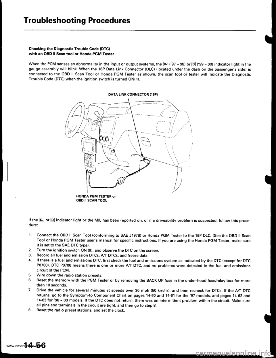
Troubleshooting Procedures
Checking ths Diagnostic Trouble Code (DTC)
with an O8D ll Scan tool or Honda PGM Tsster
When the PCM senses an abnormality in the input or output systems, the El ('97 - 98) or E ('99 - O0) indicator light in thegauge ass€mbly will blink. When the 16P Data Link Connector (DLC) {located under the dash on the passenger's side) is
connected to the OBD ll Scan Tool or Honda PGM Tester as shown, the scan tool or tester will indicate the Diagnostic
Trouble Code (DTC) when the ignition switch is turned ON(ll).
HONDA PGM TESTER olOBD II SCAN TOOL
lf the E or E indicator light or the MIL has been reported on, or if a driveability problem is suspected, follow this proce-
dure:
1. Connect the OBD ll Scan Tool (conforming to SAE J1978) or Honda PGM Tester to the 16P DLC. (See the OBD ll ScanTool or Honda PGM Tester user's manual for specific instructions. lf you are using the Honda PGM Tester, make sureit is set to the SAE DTC Wpe).2. Turn the ignition switch ON (ll), and observe the DTC on the screen
3. Record allfuel and emission DTCS, A,,/T DTCS, and freeze data.
4. lf there is a fuel and emissions DTC, first check the fuel and emissions system as indicated by the DTC (except for DTCP0700). DTC P0700 means there is one or more Ay'T DTC, and no Droblems were detected in the fuel and emissionscircuit of the PCM.
5. Wire down the radio station presets.
6. Reset the memory with the PGM Tester o. by removing the BACK UP fuse in the under-hood fuse/relay box for morethan 10 seconds.
7. Drive the vehicle for several minutes at speeds over 30 mph (50 km/hr), and then recheck for DTCS. lf the A/T DTCreturns, 9o to the Symptom-to Component Chart on pages 14-60 and 14-61 for the '97 models, and pages 14-62 and14-63 for '98 - 00 models. lf the OTC does not return, there was an intermittent problem within the circuit. Make sureall pins and terminals in the circuit are tight, and then go to step 8.8. Reset the radio Dreset stations, and set the clock.
DATA LINK CONNECTOR {16PI
[ -=.r,
ili,i /i,
v,., i
14-56
www.emanualpro.com
Page 576 of 1395
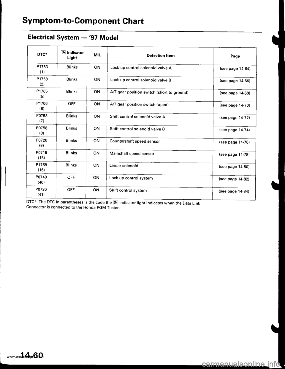
Symptom-to-Component Chart
Electrical System -'97 Model
DTC*: The DTc in parentheses is the code the loa indicator right indicates when the Data LinkConnector is connected to the Honda pGM Tester.
DTC*E Indicatol
LightMILDetection ltemPage
P 1753
(1)BlinksONLock up control solenoid valve A(see page 14-64)
P1758
\21
B linksONLock-up control solenoid valve B(see page 14-66)
P 1705
(5)BlinksONA,/T gear position switch (short to ground)(see page 14-68)
P1706
(6)OFFONA,/T gear position switch {open)(see page 14-70)
P0753
\11
B linksONShift control solenoid valve A(see page 14-72)
P0758
(8)BlinksONShift control solenoid valve B(see page 14-74)
P0720
(9)BlinksONCountershaft speed sensor{see page 14-76)
P0715
(15)B linksONMainshaft speed sensor(see page l4-78)
P17 68( 16)
BlinksONLinear solenoid(see page 14-80)
P0740
{40)
OFFONLock-up control system(see page 14-82)
P0730
(41)OFFONShift control system(see page 14-84)
14-60
www.emanualpro.com
Page 578 of 1395
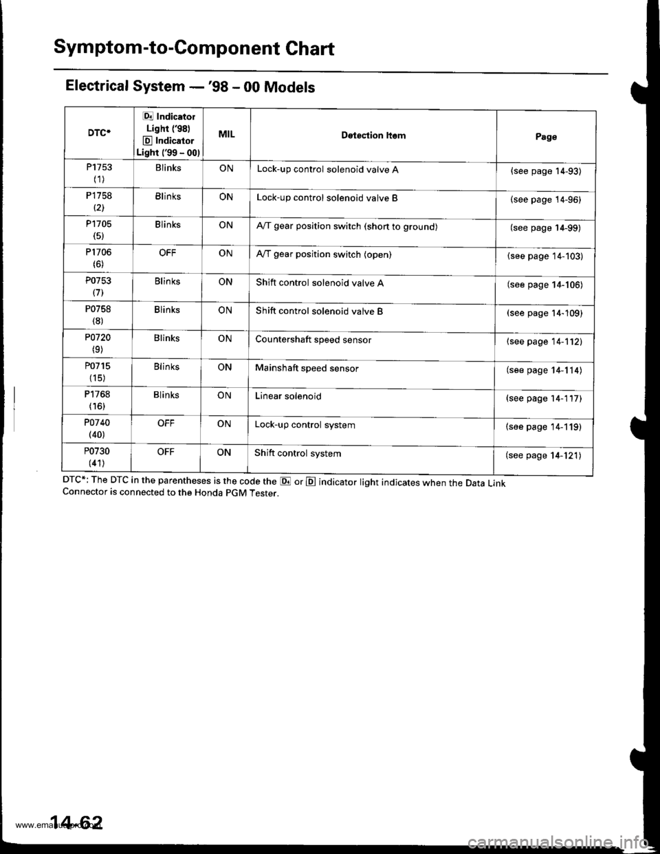
Symptom-to-Component Chart
Electrical System -'98 - 00 Models
DTC*; The DTC in the parentheses is the code the E or E indicator light indicates when the Data LinkConnector is connected to the Honda pGM Tester.
DTC*
Et Indicatol
Lighr (98)
E Indicator
Light ('99 - 00)
MILDetestion ltomPage
P1753
(1)BlinksONLock-up control solenoid valve A{see page 14-93)
P1758
(21BlinksONLock-up control solenoid valve B(see page 14-96)
P1705(5)BlinksONA,/T gear position switch (shon to grounol(see page 14-99)
P1706(6)OFFONA,/T gear position switch (open)(see page 14-103)
P0753
(71Blin ksONShift control solenoid valve A(see page 14-106)
P0758
(8)BlinksONShift control solenoid valve B(see page 14-109)
P0720
(9)BlinksONCountershaft speed sensor{see page 14-112)
P0715
{15)
BlinksONMainshaft speed sensor(see page 14-114)
P1768
(16)BlinksONLinear solenoid(see page 14-117)
POl 40(40)OFFONLock-up control system(see page 14-119)
P0730
(41)OFFONShift control system(see page 14-121)
14-62
www.emanualpro.com
Page 642 of 1395
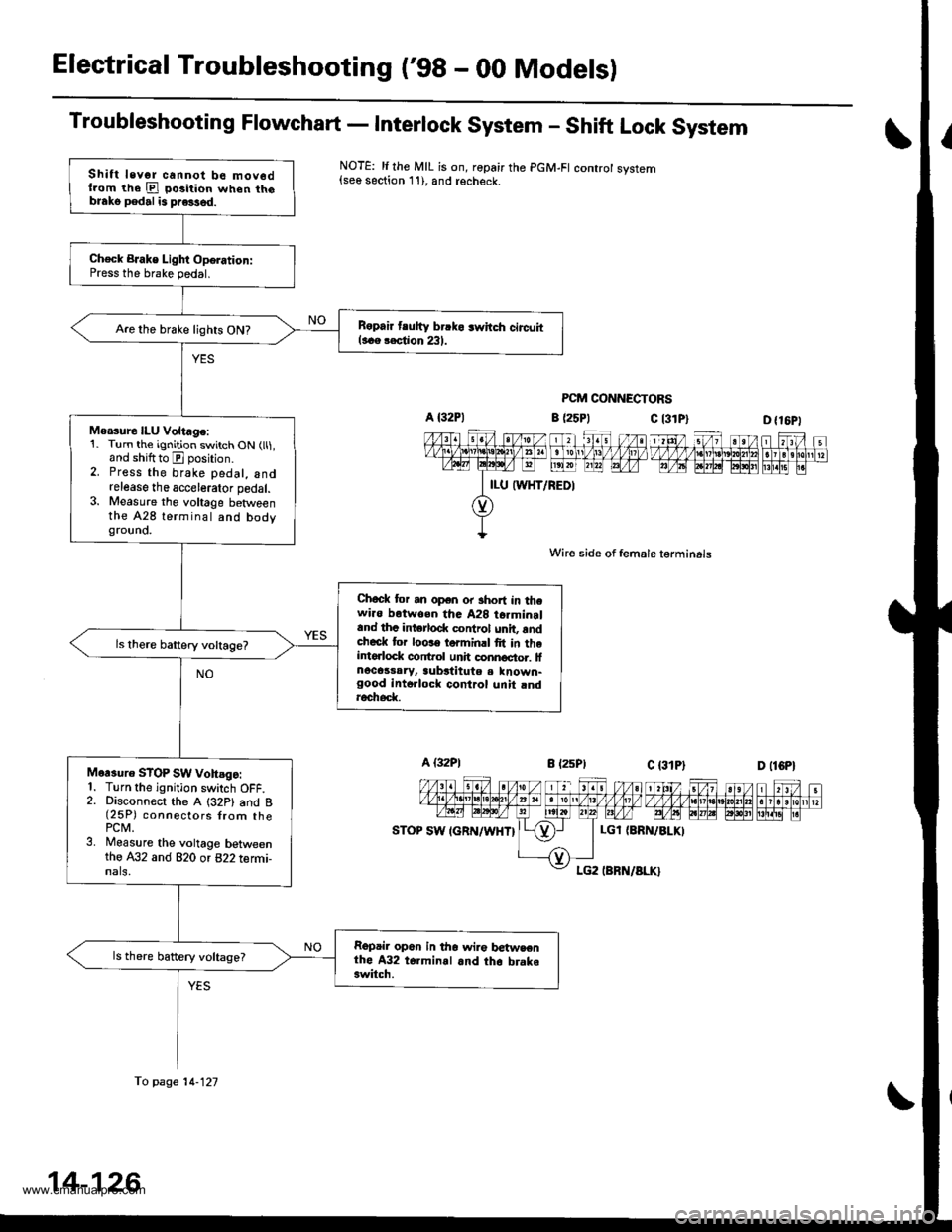
Electrical Troubleshooting ('98 - 00 Modelsl
Troubleshooting Flowchart - Interlock System - Shift Lock System
NOTE: li the MIL is on, ropair the PGM-FI controt system{see section 11), and recheck.
PCM CONNECTORS
c l3lPl
Wire side of female lerminals
c t3lPt
D {16P1
1 tttt/ 5t/ 1 a t /tlt 1 t\/t ,/ VVV tl t ttj,r\1e\10l211n . I 3 rholr1 t?m@-@Effilil"
D (lCPl
| 2ttt/ ;t /n) ).tt)/ 1 21:/ tvvvvv nnvl.lnl2
I r r ero
12wE gp]P] polr EI!l!!i r.
a (25P1
LGl {8RN/ALKI
Shift levor cannot be mov6dllom the E po3ition when th6blako pedal is pre3sed.
Ch€ck BJake Light Oporation:Press the brake pedal.
B6pair tlutty brrko 3whch circuitl..e rection 231.Are the brake lights ON?
Me.sure ILU Voltage:1. Turn the ignition switch ON (ll1,and shiftto E position.2. Press the brake pedal, andrelease the accelerator pedal.3. Measure the voltage betweenthe A28 terminal and bodygrouno.
Chock tor an open or short in thewi.o botwoen tha A28 t6rminrland thc intorlod( control unit, rndcheck tor loose torminrl fit in theintorlock conftol unh connoctor. lfnocassaryr aubstitute a known-good intollock control unit rndroch6d(
Mor3uro STOP SW vohsgo:1. Turn the ignition switch OFF.2. Disconnect the A (32P1 and B(25P) connectors {rom thePCM.3. Measure the voltage betweenthe A32 and 820 or 822 termi-nals,
Repair op6n in tho wir€ betwsenthe A32 t6.minal and th6 brake3witch.
ls there battery voltage?
fo page 14-121
14-126
www.emanualpro.com
Page 702 of 1395
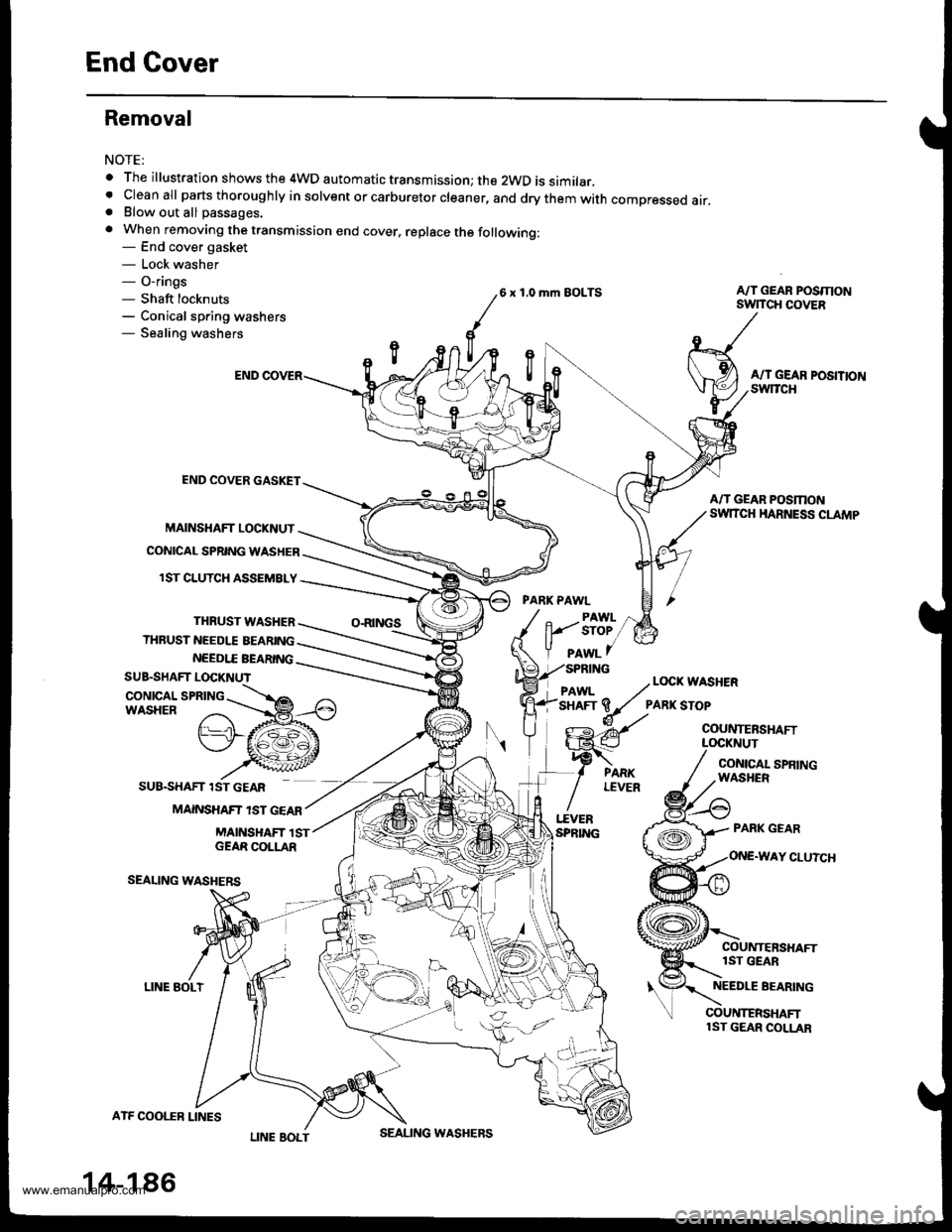
End Cover
Removal
NOTE:
o The illustration shows the 4WD automatic transmission; the 2WD is similar.. cleanall parts thoroughly in solvent or carburetor cleaner, and drythem with compressed air.. Blow out all passages.
. When removing the transmission end cover, replace the following:- End cover gasket- Lock washer- O-rings- Shaft locknuts- Conical spring washers- Sealing washers
END COVER GASKET
MAINSHAFT LOCKNUT
CONICAL SPRING WASHER
6 x 1 .0 rhm EOLTS
PARK PAWL
A/T GEAR POSMONSwlTCH COVER
NEEDI.T BEARING
SUB.SHAFT LOCKNUT
CONICAL SPRINGWASHER
LINE AOLT
ATF COOI.f B LINES
14-186
PAwL 7// Locx wASHER
'sHAFr 9/ ?ARK srop
o-- Ay' couNTERsHAFr
G-€ LocKNUr!€ / ..t,"o, "oo
A/T GEAR POSMONSW|TCH HARNESS CLAMP
CONICAL SPRINGWASHCR
A/T GEAR POSITION
PARK GEAR
Y CLUTCH
lST GEAR
NEEDLE BEARING
1ST CLUTCH ASSEMBLY
THRUST WASHER
THRUST NEEDLE AEARING
O.RINGS
\\
SUB.SHAFT 1ST GEAR
MAINSHAF? 'ST GEAR
MAINSHAFT 1STGEAR COLLAR
SEALING WASHERS
!€'-l
I"EVERSPRING
COUNTERSHAFTlST GEAR COLLAR
PAWL
lt1/ sroe
Y plwl f
L/'SPRING
LOCKNUT
LINE BOLTSEALING WASHERS
www.emanualpro.com
Page 704 of 1395
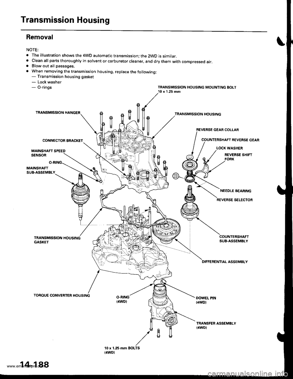
Transmission Housing
Removal
NOTE:
. The illustration shows the 4WD automatic transmission; the 2WD is similar,. Cleanall parts thoroughly in solvent or carburetor cleaner. and drythemwith compressed air.. Blow out all passages.
. When removing the transmission housing, replace the lollowing:- Transmission housing gasket- Lock washer- O-rings
TRANSMISSION HANGERTRANSMISSION HOUSING
REVERSE GEAN COLLAR
TRANSMISSION HOUSING MOUNTING EOLT
CONNECTOR BRACKET
MAINSHAFT SPEEDSENSOR
REVERSE GEAR
LOCK WASHER
REVERSE SHIFT
MAINSHAFTSUB.ASSEMBLY
TRANSMISSION HOUSINGGASKET
DIFFERENTIAL ASSEMBLY
TOROUE CONVERTER HOUSINGO-RINGt4wDl
TRANSFER ASSEMBLYt4wDt
10 x 1.25 mm
l4wo)
14-1 88
BOLTS
www.emanualpro.com
Page 706 of 1395
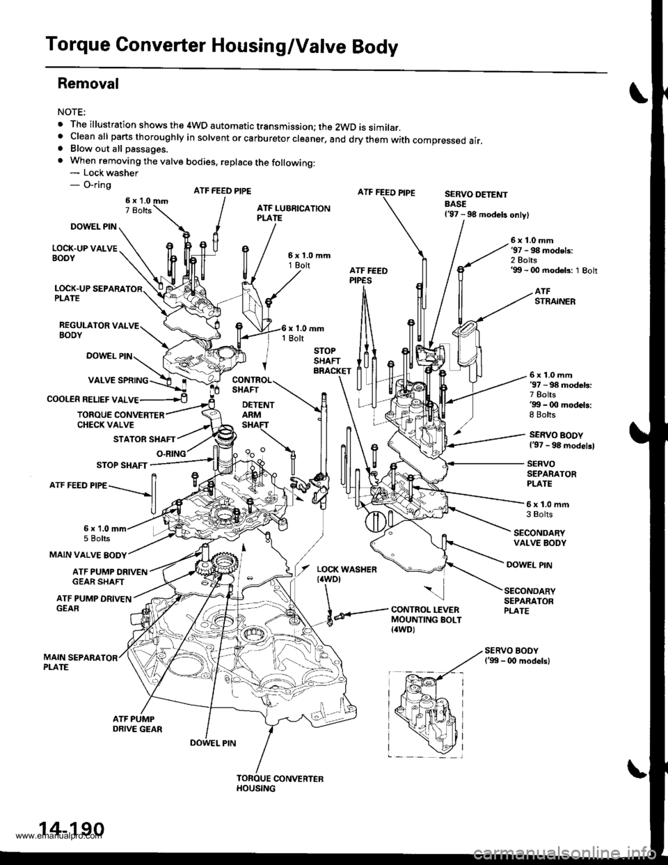
Torque Converter Housing/Valve Body
Removal
NOTE:
. The illustration shows the 4WD automatic transmission; the 2WD is similar.' cleanall parts thoroughry in sorvent or carburetor creaner, and drythem with compressed air.. Blow out all passages.
. When removing the valve bodies, replace the following:- Lock washer- O-ringATF FEED PIPESERVO DETENTBASE137 - 98 models only)
DOWEL PIN
LOCK.UP VALVEBOOY
6x1.0mm'97 - 98 models:2 Bolts'99 - 00 modeb: 1 Bolt
LOCK.UP SEPARAPLATE
REGULAIOR VALVEBOOY
ATFSTRAINER
DOWEL PIN
COOLER RELIEF VALVE
6x1.0mm37 - 98 models:7 Bolts'gg - 0O models:8 Bolts
SERVO BODY137 - 98 modelsl
SERVOSEPARATORPLATE
TOROUE CONVERTERCHECK VALVE
STATOR SHAFT
O.RING
5x1.0mfi3 Bolts
SECONDARYVALVE BODY
MAIN VALVE BODY
6x 1.05 Bolts
ATF PUMP ORIVENGEAR SHAFT
DOWEL PIN
ATF PUMP DRIVENGEAR
\
CONTROL LEVERMOUNTING BOLT{awD)
SECONDARYSEPARATORPLATE
14-190
www.emanualpro.com
Page 740 of 1395
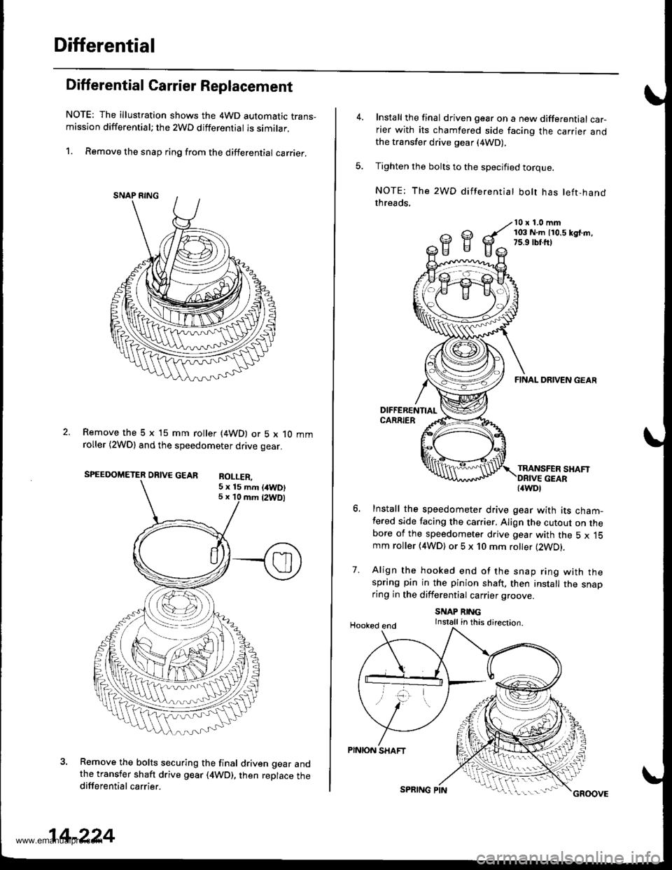
Differential
Differential Carrier Replacement
NOTE: The illustration shows the 4WD automatic trans-mission differential; the 2WD differential is similar.
1. Remove the snap ring from the differential carrier.
Remove the 5 x 15 mm roller (4WD) or 5 x 10 mmroller (2WDl and the speedometer drive gear.
SPEEDOMETER DRIVE GEAR RoI I FP
Remove the bolts securing the final driven gear andthe transfer shaft drive gear (4WD), then replace thedifferential carrier.
5 x 15 mm (/tWD)5 x 10 mm {2WDl
14-224
SPRING PINGROOVE
Install the final driven gear on a new differential car-rier with its chamfered side facing the carrier andthe transfer drive gear (4WD),
Tighten the bolts to the specified torque.
NOTE: The 2WD differentiat bolt has left-handthreads,
10 x 1.0 mm103 N.m 110.5 kd.m,7s.9 rbr.ft)
7.
FINAL DRIVEN GEAR
TRANSFER SHAFT
Install the speedometer drive gear with its cham-fered side facing the carrier. Align the cutout on thebore of the speedometer drive gear with the 5 x 15mm roller (4WD) or 5 x 10 mm roller (2WD).
Align the hooked end of the snap ring with thespring pin in the pinion shaft. then install the snaoring in the differential carrier groove
SNAP RINGInstall in this direction.Hooked end
PINION SHAFT
{4WDl
www.emanualpro.com
Page 766 of 1395
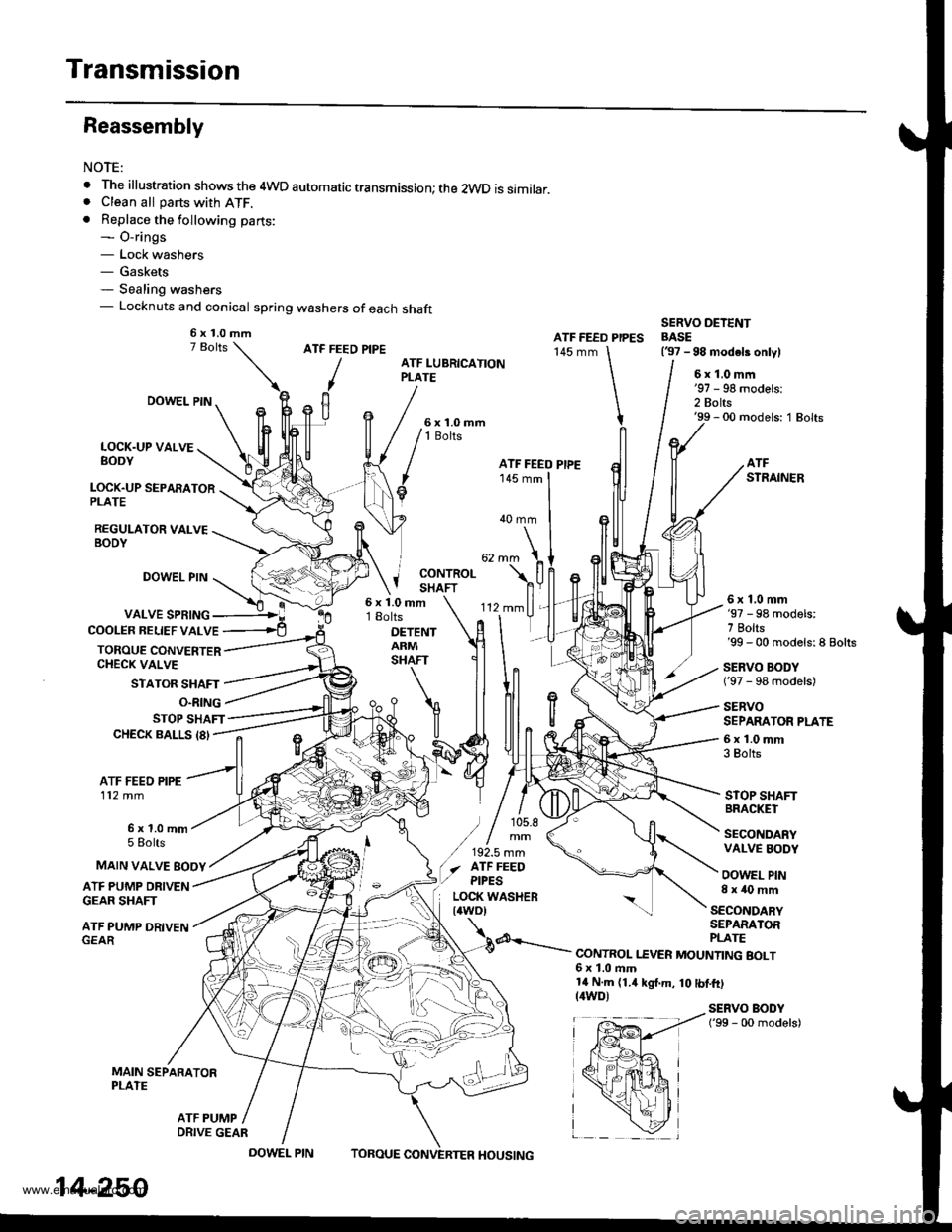
Transmission
Reassembly
NOTE:
. The illustration shows the 4WD automatic transmission; the 2WD is similar.. Clean all parts with ATF.. Replace the following parts:- O-rings- Lock washers- Gaskets- Sealing washers- Locknuts and conical spring washers of each shaft
ATF FEED PIPE
/
ATF FEED PIPES145 mm
SERVO DETENTBASE(37 -98 modeb onlylATF LUBRICATIONPLATE6x1.0mm
2 Bolts'99 - 00 models: 1 Bolts
LOCK.UP VALVEBODY
LOCK.UP SEPARATORPLATE
REGULATOR VALVEBODY
DOWEL PIN
DOWEL PIN
VALVE SPRING
STATOR SHAFT
'-
'112mmll,
rlT
ATFSTRAINER
40 mm
j coNrRoLI SHAFT
COOLER BELIEF VALVE
TOROUE CONVERTERCHECK VALVE
6x1.0mm18olts
DETENTARMSHAFT
6x1,0mm'97 - 98 models:7 Bolts'99 - 00 models:8 Bolts
SERVO BODY('97 - 98 models)
SERVOSEPARATOR PLATE
6x1.0mm3 Bolts
STOP SHAFTBRACKET
SECONDARYVALVE BODY
OOWEL PIN8x40mm
O.RING
STOP SHAFTCHECK BALLS 18'
ATF FEED PIPE112 mm
6x1.0mm5 Eolts
ATF PUMP DRIVENGEAR SHAFT
ATF PUMP DRIVEN
MAIN SEPARATORPLATE
MAIN VALVE EOOY
SECONDARYSEPARATOR
d---.- PLATE--.- CONTROL I.EVER MOUNTING BOLT6x1.0ftm14 N.m (1.4 kgt.m, 10 tbf.ft)(4WD)SERVO BODY('99 - 00 models)
ATF PUMP
6x1.0mm
ATF FEEO PIPE
) / 105.8
/,,!.,::(./ afF FEEO,/ ptpEs
EP,---!ir{+*a r
fpffi4 i
x*hi
_ \zl
14-250
DRIVE GEAR
DOWEL PINTOBOUEHOUSING
www.emanualpro.com
Page 910 of 1395
Front Suspension
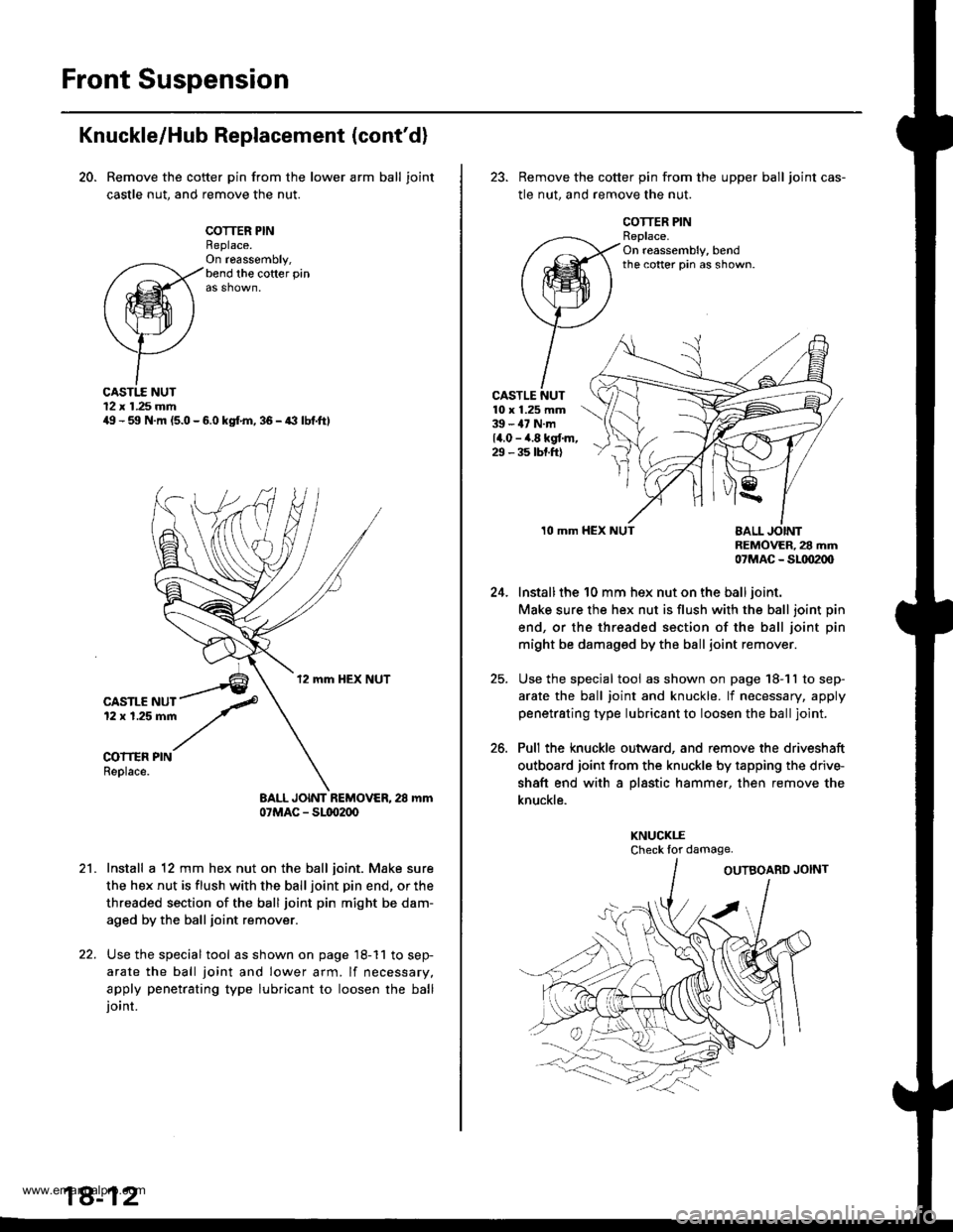
Knuckle/Hub Replacement (cont'd)
20. Remove the cotter pin from the lower arm ball joint
castle nut, and remove the nut.
COTTER PINReplace.On ra6ssembly,bend the cofter pin
CASTI.E NUT12 x 1.25 mmilg - 59 N.m (5.0 - 6.0 kgf.m, 36 - a3 lbf.ftl
CASTLE NUT12 x 1.25 mm
COITER PINReplace.
BALL JOINT REMOVER, 28 mm07MAC - Sl(xr2(x,
Install a 12 mm hex nut on the ball joint. Make sure
the hex nut is flush with the ball joint pin end, or the
threaded section of the ball joint pin might be dam-
aged by the ball joint remover.
Use the special tool as shown on page 18-11 to sep-
arate the ball joint and lower arm. lf necessary,
apply penetrating type lubricant to loosen the balljoint.
18-12
23. Remove the cotter pin from the upper ball joint cas-
tle nut, and remove the nut.
COTTER PINReplace.On reassembly, bendthe cotter pin as shown.
CASTLE NUT10 x 1.25 mm39 - 47 N.m14.0 - ,4.8 kgt m,29 - 35 tbt.ftl
24.
25.
26.
10 mmnEMOVER, 28 mm07MAC _ SLtD2(xl
Install the 10 mm hex nut on the ball joint.
Make sure the hex nut is flush with the ball joint pin
end, or the threaded section of the ball joint pin
might be damaged by the ball joint remover.
Use the special tool as shown on page 18-11 to sep-
arate the ball joint and knuckle. lf necessary, apply
penetrating type lubricant to loosen the ball joint.
Pull the knuckle outward, and remove the driveshaft
outboard joint from the knuckle by tapping the driv+
shaft end with a pl8stic hammer, then remove the
knuckle.
KNUCKI.ECheck lor damage.
www.emanualpro.com