Mil HONDA CR-V 1998 RD1-RD3 / 1.G Repair Manual
[x] Cancel search | Manufacturer: HONDA, Model Year: 1998, Model line: CR-V, Model: HONDA CR-V 1998 RD1-RD3 / 1.GPages: 1395, PDF Size: 35.62 MB
Page 349 of 1395
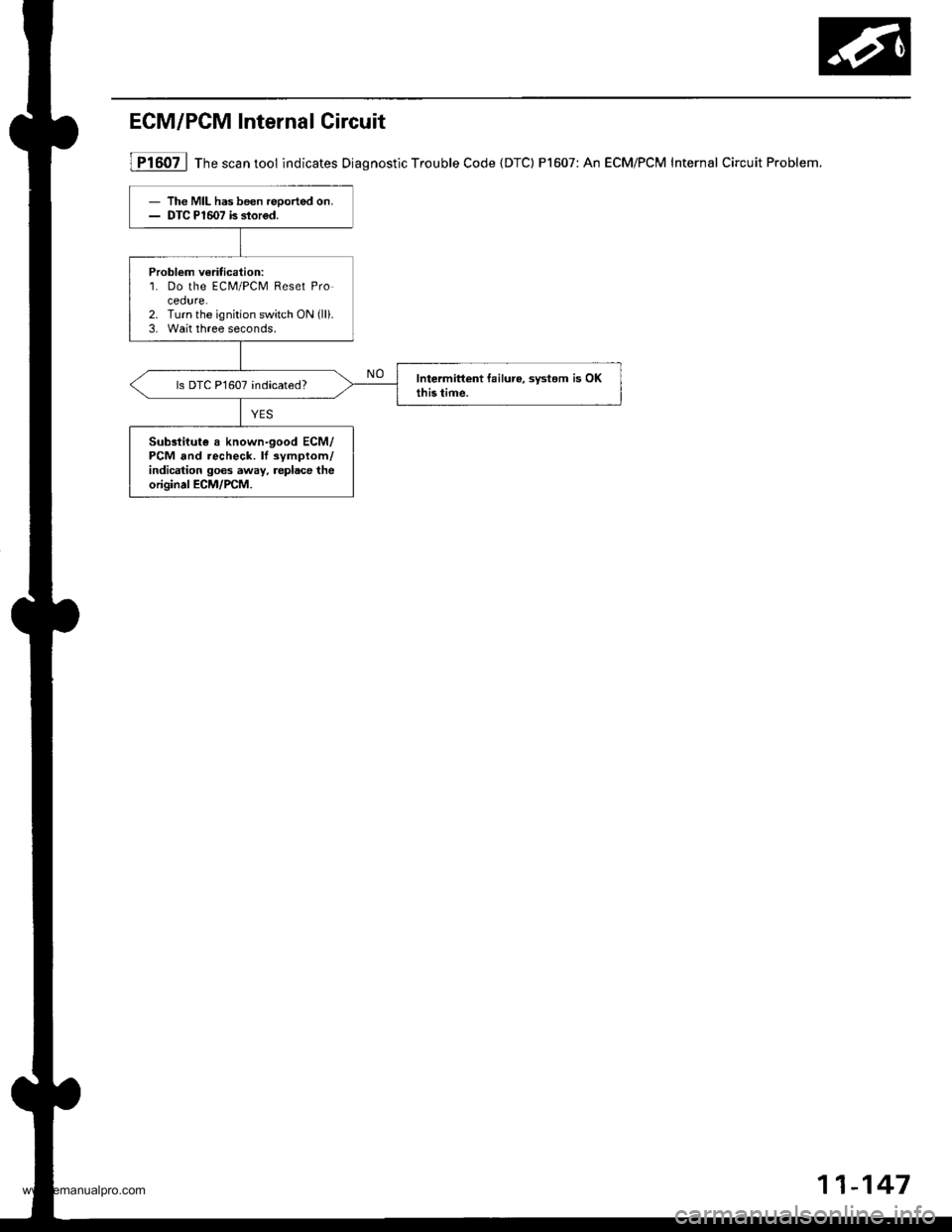
ECM/PCM Internal Circuit
lFi6oil Th" """n tool indicates Diagnostic Trouble Code {DTC) P1607: An ECM/PCM Internal Circuit Problem.
- The MIL has been reoorted on.- DTC PlmT is slor6d.
Problom veritication:1. Do the ECM/PCM Reset Pro
2. Turn the ignition switch ON (ll).
3, Wait three seconds,
ls DTC P1607 indicated?
Sub3tiiut€ a known-good ECM/PCM and recheck. lf symptom/indication goes away, replace theoriginal ECM/rcM.
11-147
www.emanualpro.com
Page 352 of 1395

ldle Control System
ldle Control System
I P0505 | The scan tool indicates Diagnostic T.ouble Code (DTCI PO5O5: ldlecontrol svstem mattunction.
NOTE: lf DTC P1508 is stored at the same time as DTC P0505, troubleshoot DTC P1508 first. then troubleshoot DTC p0505.
Possibls Cause
. IAC valve mechanical malfunction. Throttle body clogged port, improper adlustment. Intake manifold gasket leakaging. Intake air hose loose leakaging. Vacuum hose leakaging
a ECT sensor incorrect output. Throttle Position sensor incorrect output
Troubleshooting Flowchart
The MIL has been reDorted on.DTC P0505 is sto.ed.
Problem verificationi1. Start the engine. Hold theengine at 3,000 rpm with noload (in Park or neutral) untilthe radiator Ian comes on, thenlet it idle.2. With the scan tool, check thelollowing items.- Throttle position should beapprox. 10% with the throt-tle {ully closed.- Engine coolant temperature shorJld be 194 - 205'F(90 - 96"C).lf they are not within thespec., repair the faulty sen-sor circuit.3 Check the engine speed atidle with no-load conditions:headlights, blower fan. reardefogger, radiator lan, and airconditioner are not operaling,
Inte.mittent failure. syltem is OKat this time.ls it 750 {730)* i 50 rpm?
ls il 700 (680)' rpm or less?
{To page 11-151)(To page 1'l-151)
l:'99 - 00 models
www.emanualpro.com
Page 354 of 1395
ldle Control System
ldle Air Control llAC) Valve
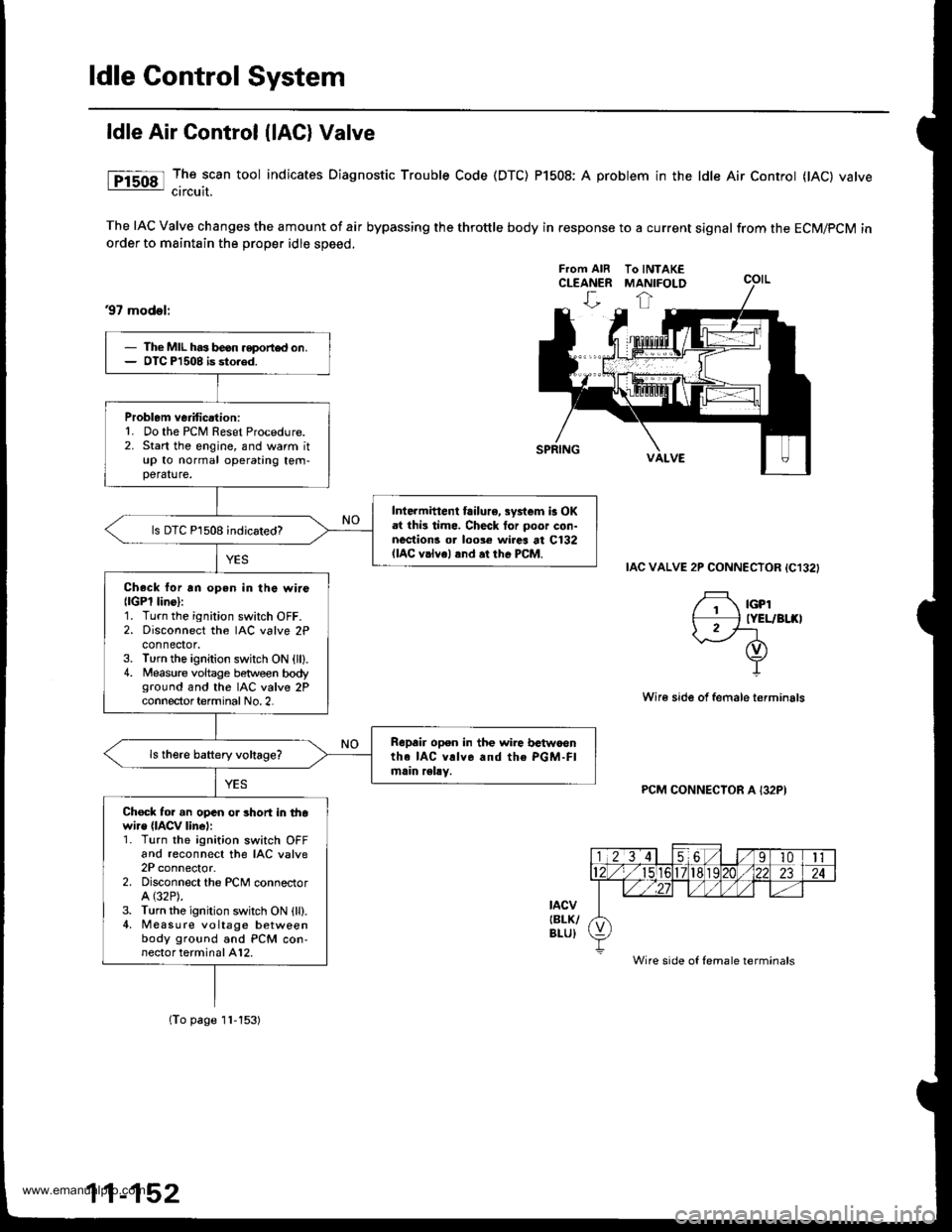
The scan tool indicates Diagnostic Trouble Code (DTC) Pl508: A probtem in the ldle Air Controt flAC) varvecircuit.
The IAC Valve changes the amount of air bypassing the throttle body in response to a current signal from the ECM/PCM inorder to maintain the proper idle speed.
37 model;
IAC VALVE 2P CONNECTOR {C132}
,f rcp'# IYEL/BI.(II2f-1-d)
Y
Wir€ side of female terminals
PCM CONNECTOR A I32PI
tacvIBLK/BLU)
From AIR To INTAKECLEANER MANIFOLD
Wire side of female terminals
The MIL has beon .eport€d on.OIC Pl508 is sto.ed.
Problem veiification:1. Do the PCM Reset Procedure.2. Start the engine, and warm itup to normal operating tem-perature.
Inte.mittent failure, systcm b OKat thi3 time. Check tor poo. con-nections or loose wircs at C132(lAC v.lvel and at the PCM.
ls DTC Pl508 indicated?
Check lor an open in the wir6{lGPl lins}:1. Turn the ignition switch OFF.2. Disconnect the IAC valve 2Pconnector.3. Turn the ignition switch ON {ll).4. Measure voltage between bodyground and the IAC valve 2Pconnector term inal No.2.
Repair open in the wire trctwoontha IAC v!lv6 and the PGM-Flmain relly.
Chock for an opan o. short in thowi.e (lACv linel:1. Turn the ignition switch OFFand reconnect the IAC valve2P connector.2. Disconnect the PCM conneclorA (32P).
3. Turn the ignition switch ON {ll).4, Measure voltage betweenbody ground and PCM con-nector terminal A12.
{To page 1l-153)
www.emanualpro.com
Page 356 of 1395
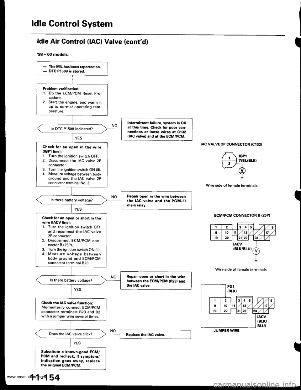
The MIL has boen r.ported on.DIC Pl 508 b 3tored.
Problem veritication:L Do the ECM/PCM Reset Pro-cedure.2. Start the engine, and warm itup to normal operating tem-perature.
Int€rmittent failure, systom is OKal lhis timo. Check lor poor con-nections or looro wirca at C132(lAc vrlvel and .t rho EcM/PcM.
ls DTC P1508 indicated?
Chock tor an open in the wir6llGPl linel:1. Turn the ignition switch OFF.2. Disconnect the IAC valve 2Pconnector,3. Turn the ignition switch ON (ll).4. Measure voltage between bodyground and the IAC valve 2Pcon nector termina I No, 2.
Repair opon in the wira botwoonthe IAC valve and tho PGM-FImain aalay.
Check tor an open or short in thewire (IACV linel:1. Turn the ignition switch OFFand reconnect the IAC valve2P connector.2. Disconnect ECM/PCM con-nector B {25P).3. Turn the ignition switch ON {ll}.4. Measure voltage betweenbody ground and ECM/PCMconnector terminal 823.
Ropair open or short in thg wirebetween tho ECM/FCM lB23l andthe IAC valve.
ls there battery voltage?
Check the IAC valve func,tion:Momentarily connect ECM/PCMconnector terminals 823 and 82with a jumper wire several times.
Does the IAC valve click?
Subslitute . known-good ECM/PCM .nd rechock. lf symptom/indication goes aw.y, replac.th€ original ECM/PCM.
ldle Air Control (lAC) Valve {cont'd}
'98 - 00 models:
IAC VALVE 2P CONNECTOR {C132I
F rcpt*l tYELrBLxlI2/'-- rf)
Y
Wire side ot fem.le terminals
ECM/PCM CONNECTOR B (25PI
Wire side of female torminals
258
9'to1l13t7
1920212223
tAcv(BLK/BLUIv
PG1{BLKI
12 | t3 4 58
910 111317
1920 | 121)22
tAcv(BLK/
BLU)JUMPER WIRE
www.emanualpro.com
Page 371 of 1395
ldle Speed Setting
Inspoction/Adiustmont
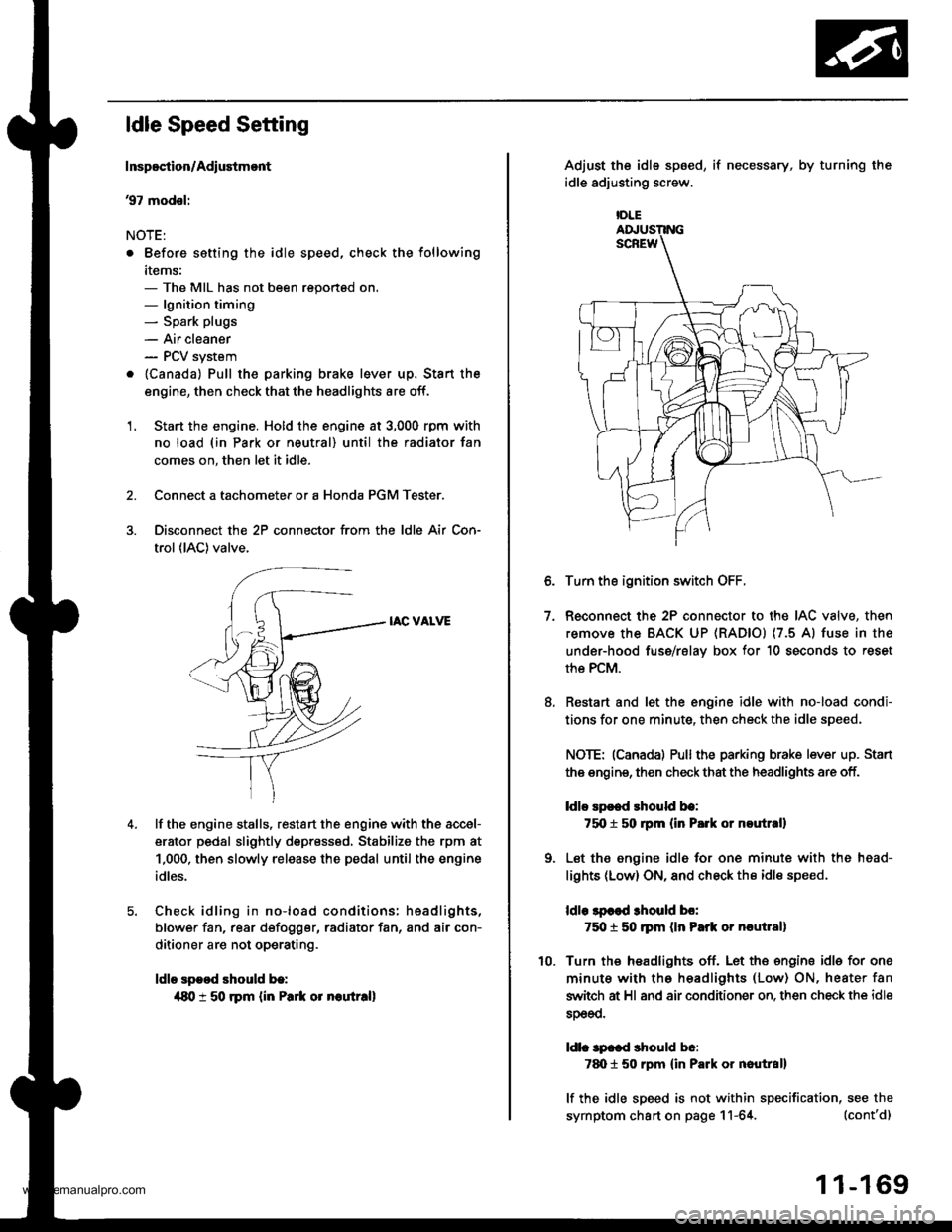
37 modsl:
NOTE:
. Before setting the idle speed, check the following
items:- The MIL has not been reportsd on.- lgnition timing- Spark plugs
- Air cleaner- PCV system
. lcanada) Pull the parking brake lever up. Stan the
engine, then check that the headlights are off.
1. Start the engine. Hold the engine at 3,000 rpm with
no load (in Park or neutral) until the radiator fan
comes on, then let it idle.
Connect a tachometer or a Honda PGM Tester.
Disconnect the 2P connector from the ldle Air Con-
trol (lAC) valve.
IAC VALVE
lf the engine stalls, restart the engine with the accel-
erator pedal slightly depr6ss6d, Stabilize the rpm at
1,000, then slowly release the pedal until the engine
idles.
Check idling in no-load conditions: hsadlights,
blower fan, rear d€fogger, radiator fan, and air con-
ditioner are not operating.
ldle spood should b.:
{80 t 50 rpm {in Park or noutr.ll
IDLE
7.
Adjust the idle sp6ed,
idle adjusting screw.
if necessary, by turning the
Turn the ignition switch OFF.
Reconnect the 2P connector to the IAC valve, then
remove the BACK UP (RAD|Ol (7.5 Al fuse in the
under-hood fuse/rslav box for 10 seconds to reset
the PCM.
Restart and let the engine idle with no-load condi-
tions for one minute, then check the idle speed.
NOTE: (Canadal Pullthe parking brake lever up. Stan
the engine, then check that the headlights are off.
ldlo Ep€ed rhould be:
75O t 50 rpm (in P.rk or noutr.ll
Let the engine idl6 for one minute with the head-
lights (Low) ON, and check th€ idl€ speed.
ldle lpcod 3hould bo:
750 t 50 ]pm (in Park or nautlal)
Turn the headlights off. Let th€ engine idle for one
minute with the headlights (Low) ON, heater fan
switch at Hl and air conditioner on. then check the idle
sDeeo.
ldl. specd should b6:
7d) 1 50 rpm {in Park or nautral}
lf the idle speed is not within specification, see the
symptom chart on page 11-64. (cont'd)
1 1-169
www.emanualpro.com
Page 372 of 1395

ldle Control System
ldle Speed Setting (cont'd)
38 - 0O mod6l3:
NOTE: Before setting the idle speed, check the follow-
ing items:- The MIL has not been reported on.- lgnition timing- Spark plugs
- Air cleaner- PCV system
1. Start the engine. Hold the engine at 3.000 rpm with
no load (in Park or neutral) until the radiator fan
comes on, then let it idle.
Connect a tachometer.
Disconnect the IAC valve 2P connector and the EVAP
purge control solenoid valve 2P connector.
CONTROLSOLENOID VALVE
SOLENOID VALVE
lf the engine stalls, restart the engine with the accel-
erato. pedal slightly depressed. Stabilize the rpm at
1,000, then slowly release the pedal until the engine
idles.
Che€k the idle in no-load conditions: headlights, blow-
er fan, rear defogger, radiator fan, and air conditioner
are not operating,
ldle speed should bo:
480 t 50 rpm {in PErk or noutrall
11-170
lf necessary, adjust the idle speed, by turning the
idle adjusting screw.
After adjusting the idle speed, recheck the ignition
timing (see section 4). lf it is out of spec, go back to
steo 4.tDt.E
6. Turn the ignition switch OFF.
7. Reconnect the 2P connectors to the IAC valve and
the EVAP purge control solenoid valve, then do the
ECM/PCM reset procedure.
8. Restart and idle the engine with no-load conditions
for one minute, then check the idle speed.
ldle speod should be:,98 model:
750 t 50 rpm tin Park or neutral)'9!l - 00 modsls:
730 i 50 lpm lin Psrk or neutral)
NOTE: lf the idle speed increases to 780 t 50 rpm(770 1 50 rpml*, this means the EVAP system is
purging the canister. To stop the purging temporari-
ly, raise the engine speed above 1,000 rpm with the
accelerator pedal, then slowly release the pedal.*: '99 - 00 models
9. Let the engine idle for one minute with the head-
lights (Low) ON, and check the idle speed.
ldle speed should be:
38 mod6l:
750 f 50 rpm (in Palk or neutrall'99 - 00 modols:
730 t 50 rpm (in Palk or neutral)
10. Turn the headlights off. Let the engine idle for one
minute with the heater fan switch at Hl and air con-
ditioner on, then check the idle speed.
ldls spqed should be:'98 model:
780 t 50 rpm (in Park or neutrall'99 - 00 mod€ls:
7701 50 rpm lin Park or neutral)
lf the idle speed is not within specification. see the
Symptom Chart on page 11-64.
ADJUSTING
www.emanualpro.com
Page 377 of 1395
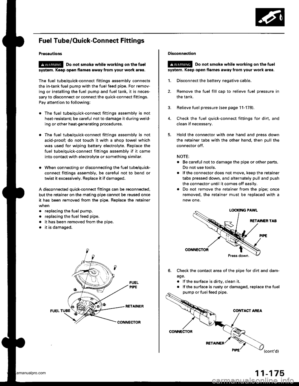
Fuel Tube/Ouick-Gonnect Fittings
Procautions
@ Do not smoke whils working on the fuel
syst6m, Koop open flames away from your work ar9a.
The fuel tube/quick-connect fittings assembly connects
the in-tank fuel pump with the fuel feed pipe. For remov-
ing or installing the fuel pump and fuel tank, it is neces-
sary to disconnect or connect the quick-connect fittings.
Pay attention to following;
. The fuel tube/quick-connect fittings assembly is not
heat-resistant; be careful not to damage it during weld-
ing or other heat-generating procedures.
. The fuel tube/quick-connect fittings assembly is not
acid-proof; do not touch it with a shop towel which
was used for wiping battery electrolyte. R€place the
fuel tube/quick-connect fittings assembly if it came
into contact with electrolyte or somethino similar.
. When connecting or disconnecting the fuel tube/quick-
connect fittings assembly, be careful not to bend or
twist it excessively, Replace it if damaged,
A disconnected quick-connect fittings can be reconnected,
but the retainer on the mating pipe cannot be reused once
it has been removed from the pipe. Replace tha retainer
. replacing the fuel pump.
. replacing the fuelfeed pipe,
. it has been removed from the Dioe,
. it is damaged.
RCTAINERFUEL TUBE
CONNECTOR
CONNECTOR
RETAINER
11-175
Disconnection
!@ Do not smoke while working on the fuel
syst6m. Keep open flames away from your work area.
1. Disconnect the battery negative cable.
2. Remove the fuel fill cap to relieve fuel pressure in
the tank.
3. Relieve fuel pressure (see page 11-178).
4. Check the fuel quick-connect fittings for dirt, and
clean if necessary.
5. Hold the connector with one hand and press down
the retainer tabs with the other hand. then pull the
connector off.
NOTE:
. Be careful not to damage the pipe or other parts.
Do not use tools,
. lf the connector does not move, keep the retainer
tabs pressed down, and alternately pull and push
the connector until it comes off easily.
. Do not remove the retainer from the pipe; once
removed, the retainer must be replaced with a
new one.
LOCKII{G PAWL
RETANEN TAB
@NNCCTOR
Press down.
6. Check the contact area of the pipe for dirt and dam-
age.
. lf the surface is dirW, clean it
. lf the surface is rusty or damaged, replace the fuel
pump or fuel feed pipe,
CONTACT ANEA
{cont'd}
www.emanualpro.com
Page 380 of 1395
Fuel Supply System
System Description
The fuel supply system consists of a fuel tank, in-tank
high-pressure fuel pump. PGM-Fl main relay, fuel filter,
fuel pressure regulator, fuel injectors, and fuel delivery
and return lines. This system delivers pressure-regulat-
ed fuel to the fuel injectors and cuts the fuel delivery
when the engine is not running.
Fuel Pressure
Relieving
Before disconnecting fuel pipes or hoses, release pres-
sure from the system by loosening the 12 mm banjo
bolt on the too of the fuel filter.
Do not smoke while working on the fuel system.
Ke€p open flames or sparks away from your work
area,
Be sure to relieve fuel pressure while the ignition
switch is off.
Write down the frequencies for the radio's preset
buttons.
Disconnect the battery negative cable from the bat-
tery negative terminal.
Remove the fuel fill cap.
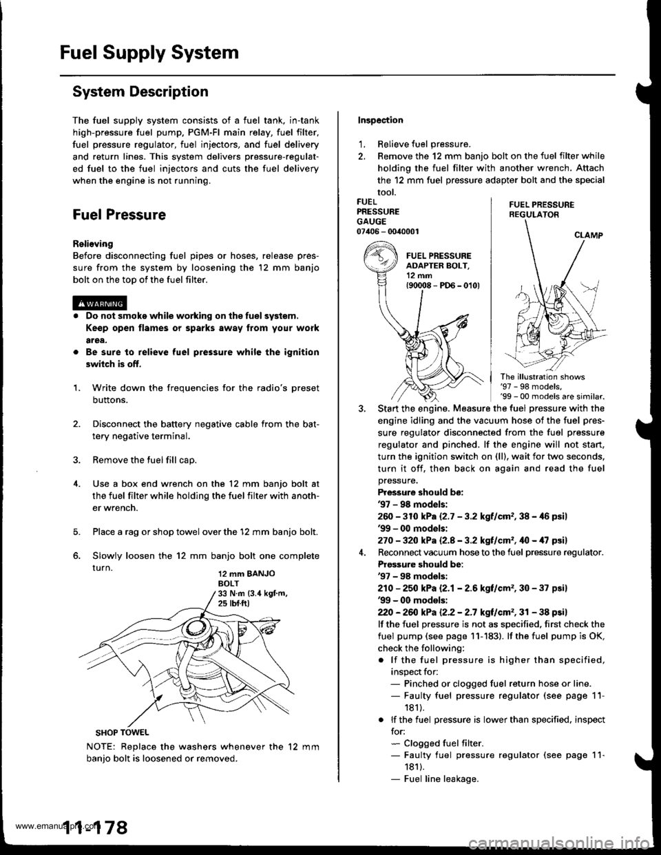
Use a box end wrench on the 12 mm banjo bolt at
the fuel filter while holding the fuel filter with anoth-
er wrench.
Place a rag or shop towel over the '12 mm banjo bolt.
Slowly loosen the 12 mm banjo bolt one complete
rurn 12 mm BANJoBOLT
1.
SHOP TOWEL
NOTE: Replace the washers whenever the 12 mm
banio bolt is loosened or removed.
11-178
Inspection
1, Relieve fuel pressure.
2. Remove the 12 mm banjo bolt on the fuel filter while
holding the fuel filter with another wrench. Attach
the 12 mm fuel pressure adapter bolt and the special
tool.
FUEL PRESSUREREGULATON
FUELPRESSUREGAUGE07406 - 0040001
The illustration shows'97 - 98 models,'99 - 00 models are similar.
Start the engine. Measure the fuel pressure with the
engine idling and the vacuum hose of the fuel pres-
sure regulator disconnected from the fuel pressure
regulator and pinched. lf the engine will not start,
turn the ignition switch on (ll), wait for two seconds,
turn it off, then back on again and read the fuel
pressure.
Pressure should be:'97 - 98 mod€ls:
260 -31O kPa 12.7 - 3.2 kgf/cm,, 38 - 46 psil'99 - 0O models:
270 - 32O kPa Q.A - 3.2 kgf/cm'�, ifo - /U psil
Reconnect vacuum hose to the fuel pressure regulator.
Prgs3ure should be:'97 - 98 models:
210 - 25O kPa 12.1- 2.6 kgf/cm'�, 30 - 37 psi)'99 - 00 models:
22O -26iJ kPa 12.2 - 2.7 kgt/cm'�, 31 - 38 psi)
lf the fuel pressure is not as specified, first check the
fuel pump (see page 11- 183). lf the fuel pump is OK,
check the following:
. lf the fuel pressure is higher than specified,
inspect for:- Pinched or clogged fuel return hose or line.- Faulty fuel pressure regulator (see page 11-
181).
. lf the fuel pressure is lower than specified. inspect
for:- Clogged fuel filter.- Faulty fuel pressure regulator (see page 11-
1811.- Fuel line leakage.
www.emanualpro.com
Page 382 of 1395
Fuel Supply System
Fuel Injectors {cont'dl
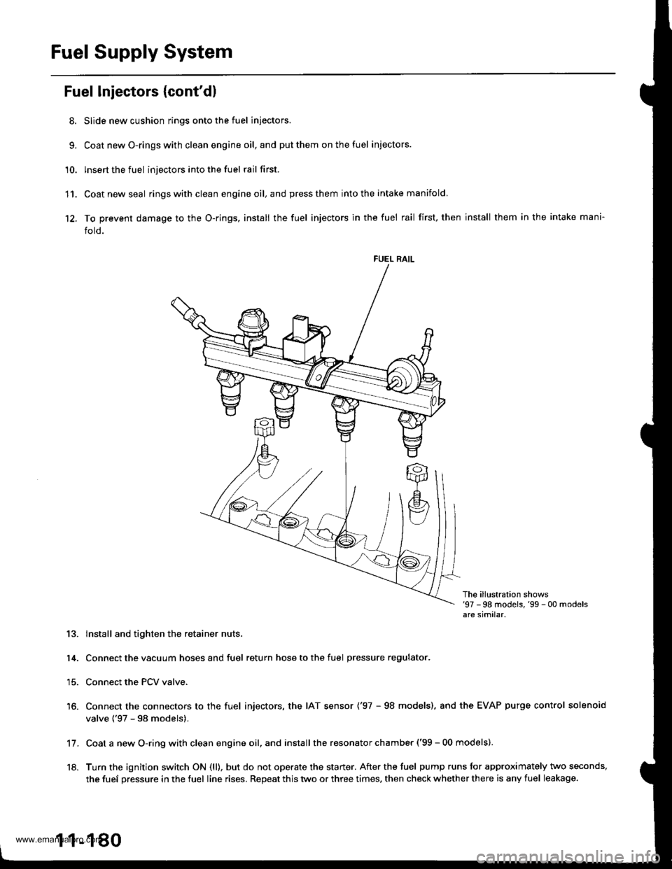
8. Slide new cushion rings onto the fuel injectors.
9, Coat newO-ringswith clean engine oil,and putthem onthefuel iniectors.
'10. lnsert the fuel injectors into the fuel rail first.
11. Coatnewseal ringswithclean engineoil,and press them into the intake manifold
12. To prevent damage to the O-rings, install the fuel injectors in the fuel rail first, then install them in the intake mani-
fold.
FUEL RAIL
The ill!stration shows'97 -98 models,'99 - 00 modelsare similar.
13. lnstall and tighten the retainer nuts.
14. Connect the vacuum hoses and fuel return hose to the fuel pressure regulator.
15. Connect the PCV valve.
16. Connect the connectors to the fuel injectors, the IAT sensor ('97 - 98 models), and the EVAP purge control solenoid
valve {'97 - 98 models).
Coat a new O-ring with clean engine oil, and install the resonator chamber ('99 - 00 models).
Turn the ignition switch ON (ll), but do not operate the starter. After the fuel pump runs for approximately two seconds,
the fuef pressure in the fuel line rises. Repeat this two or three times, then check whether there is any fuel leakage.
11.
18.
1 1-180
www.emanualpro.com
Page 383 of 1395
Fuel Pressure Regulator
Tesiing
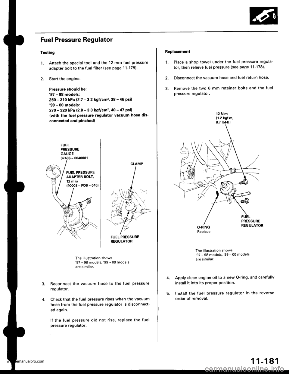
1. Attach the special tool and the 12 mm fuel pressure
adapter bolt to the fuel filter (see page 1l-178)
2. Start the engine.
Prasgure should be:'97 - 98 models;
260 - 310 kPa (2.7 - 3.2 kgl/cm'�,38 -,16 psi)'9!t - 00 models:
27O - 32o kPa l2-8 - 3.3 kgf/cm'�, 40 - /l7 psil
(with the lugl pressure rsgulator vacuum hose dis-
connested and pinched)
FUELPRESSUREGAUGE07406 - 0040001
FUEL PRESSURENEGULATOR
The illustration shows'97 - 98 models,'99 -00 modelsare similar.
Reconnect the vacuum hose to the fuel pressure
regulalor.
Check that the fuel pressure rises when the vacuum
hose from the fuel pressure regulator is disconnect-
ed agarn.
lf the fuel pressure did not rise, replace the fuel
pressure regulator.
4.
CLAMP
Replacement
'1. Place a shop towel under the fuel pressure regula-
tor, then relieve fuel pressure (see page 11-1781.
2. Disconnect the vacuum hose and fuel return hose.
3. Remove the two 6 mm retainer bolts and the fuel
pressure reguralor.
12 N.m(1.2 kgf.m,8.7 tbf.ft)
The illustration shows'97 - 98 models, '99 00 models
are similar.
Apply clean engine oil to a new O-ring. and carefully
install it into its proper position.
Install the fuel pressure regulator in the reverse
order of removal,
Replace.
1 1-181
www.emanualpro.com