light HONDA CR-V 1998 RD1-RD3 / 1.G Workshop Manual
[x] Cancel search | Manufacturer: HONDA, Model Year: 1998, Model line: CR-V, Model: HONDA CR-V 1998 RD1-RD3 / 1.GPages: 1395, PDF Size: 35.62 MB
Page 794 of 1395

Description
Rear Differential
Outline
The Real-time 4WD-Dual Pump System model has a hydraulic clutch and a differential mechanism in the rear differential
assembly. Under normal conditions, the vehicle is driven by the front wheels. However, depending on to the driving force
of the front wheels and the road conditions. the system instantly transmits appropriate driving force to the rear wheels
without requiring the driver to switch between 2WD (tront wheel drive) and 4WD (four wheel drive). The switching mecha-
nism between 2WD and 4WD is integrated into the rear differential assembly to make the system light and compact.
ln addition, the dual-pump system switches off the rear-wheel-drive force when braking in a forward gear. This allows the
braking system to work properly on models equipped with an Anti-lock Braking System (ABS).
Construction
The rear differential assembly consists of the torque control differential case assembly and the rear differential carrier
assembly. The torque control differential case assembly consists of the differential clutch assembly, the companion
flange, and the oil pump body assembly. The rear differential carrier assembly consists of the differential mechanism. The
differential drive and driven gears are hypoid gears.
The oil pump body assembly consists of the front oil pump, the rear oil pump, the hydraulic control mechanism, and the
clutch piston. The clutch piston has a disc spring that constantly provides the differential clutch assembly with a preset
torque to Drevent abnormal sound.
The clutch guide in the differential clutch assembly is connected to the propeller shaft via the companion flange, and it
receives the driving force lrom the transfer assembly. The clutch guide rotates the clutch plate and the front oil pump in
the oil pump body.
The clutch hub in the differential clutch assembly has a clutch disc that is splined with the hypoid drive pinion gear. The
hypoid drive gear drives the rear oil pump.
The front and rear oil pumps are trochoidal pumps. The rear oil pump capacity is 2.5 percent larger that the front oil pump
to handle the rotation difference between the front and rear wheels caused by worn front tires and tight corner braking.
The oil pumps are designed so the fluid intake works as a fluid discharge when the oil pumps rotate in reverse. Genuine
Honda CVT fluid is used instead of differential fluid.
Operation
When there is a difference in rotation speed between the front wheels (clutch guide) and rear wheels (hypoid driven gear),
hydraulic pressure from the front and rear oil pumps engages the differential clutch, and drive force from the transler
assembly is applied to the rear wheels.
The hydraulic pressure control mechanism in the oil pump body selects 4WD mode when the vehicle is started abruptly,
or when accelerating in a forward or reverse gear (causing rotation difference between the front and rear wheels). or
when braking in reverse gear {when decelerating). lt switches to 2WD mode when the vehicle is driven at a constant speed
in forwar! or reverse gear (when there is no rotation difference between the front and rear wheels), or when braking in a
fo rwa rd gear (when decelerating).
To protect the system, the differential clutch assembly is lubricated by hydraulic pressure generated by the oil pumps in
both 4WD and 2WD modes. Also, the thermal switch relieves the hydraulic pressure on the clutch piston and cancels 4WD
mode if the temDerature of the differential fluid rises above normal.
www.emanualpro.com
Page 818 of 1395
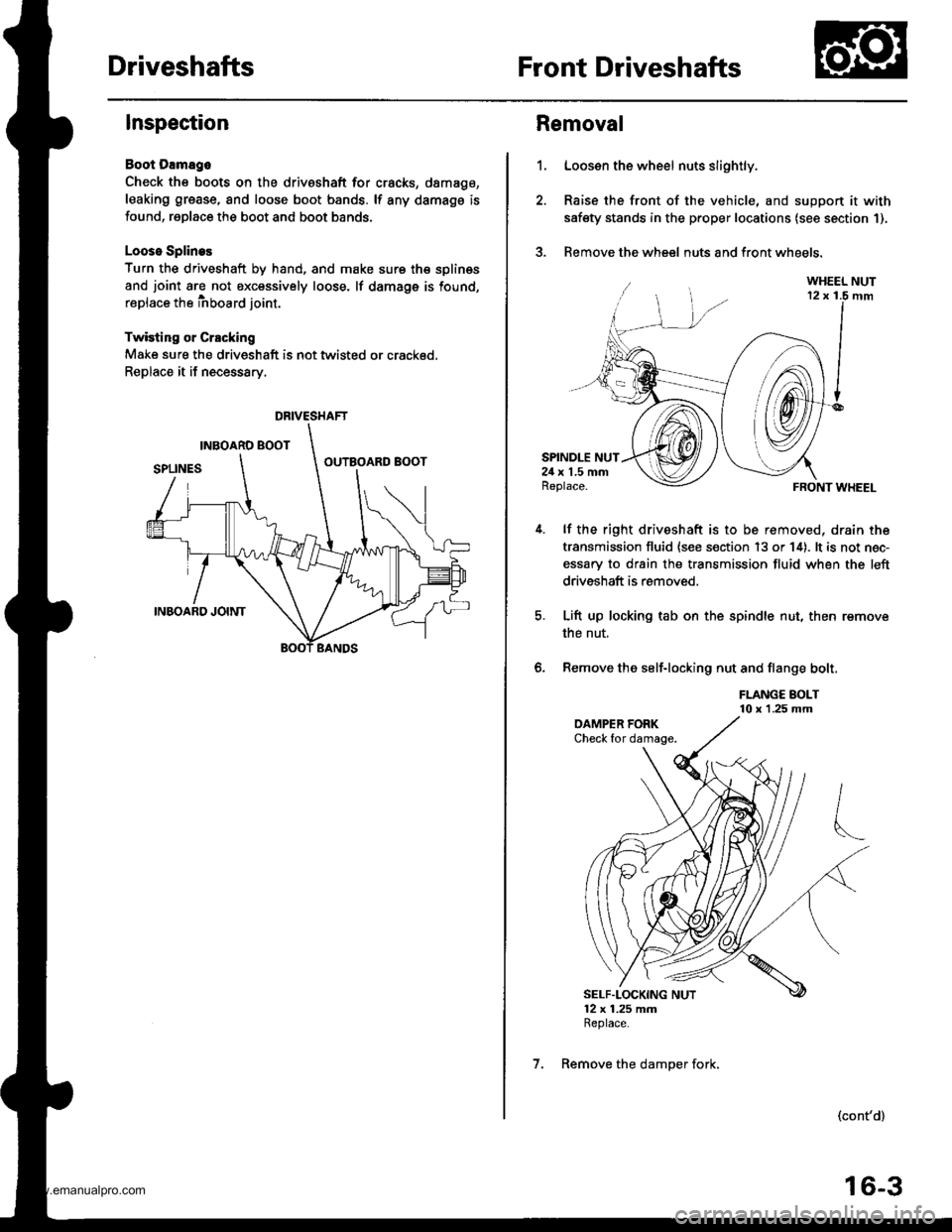
DriveshaftsFront Driveshafts
Inspection
Boot Damago
Check the boots on the driveshaft for cracks, damago,
leaking grease, and loose boot bands. lf any damags is
found, replace the boot and boot bands.
Looso Splines
Turn the driveshaft by hand, and make sure th€ splin€s
and joint are not excessively loose. lf damage is found,
replace the inboard joint.
Twisting or Crscking
Make sure the driveshaft is not twisted or crackod.
Replace it if necessary.
DRIVESHAFT
1.
Removal
Loosen the wheel nuts slightly.
Raise the front of the vehicle, and suppon it with
safety stands in the proper locations (see section 1).
Remove the wheel nuts and front wheels.?
SPINDLE NUT24 x 1.5 mmReplace.
lf the right driveshaft is to be removed, drain the
transmission fluid {see s€ction 13 or 14). lt is not nec-
essary to drain the transmission fluid when the left
driveshaft is removed.
Lift up locking tab on the spindle nut, then remove
the nut,
Remove the self-locking nut and flange bolt,
FLANGE BOLT10 x 1.25 mm
FRONT WHEEL
(cont'd)
6.
SELF"LOCKING NUT12 x 1.25 mmReplace.
7. Remove the damper fork,
16-3
www.emanualpro.com
Page 837 of 1395
Rear Driveshafts
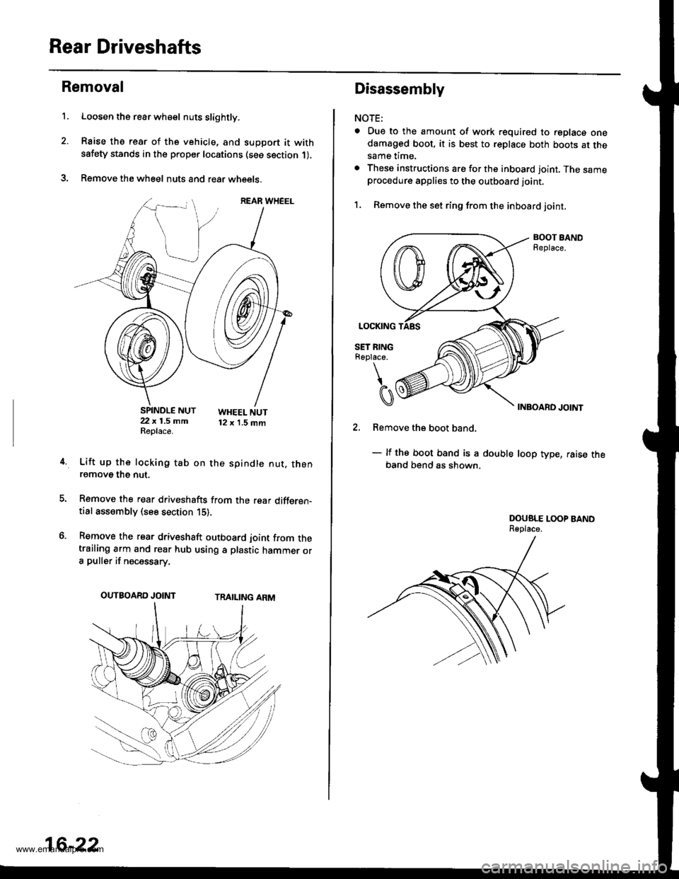
't.
Removal
Loosen the rear wh€el nuts slightly.
Raise the rear of the vehicle, and support it withsafety stands in the proper locations (see section 1),
Remove the wheel nuts and rear wheets.
SPINDLE NUT22 x 1.5 mmReplace.
WHEEL NUT12 x 1.5 mm
4.Lift up the locking tab on the spindle nut. thenremove the nut.
Remove the rear driveshafts from the rear differen-tial assembly (see section 15),
Remove the rear driveshaft outboard joint from thetrailing arm and rear hub using a plastic hammer ora puller if necessary.
TRAILING ARMOUTBOARD JOINT
16-22
Disassembly
NOTE:
a Due to the amount of work required to replace onedamaged boot, it is best to replace both boots at thesame time.
. These instructions are for the inboard joint. The sameprocedure applies to the outboard joint.
1, Remove the set ring from the inboard joint,
BOOT BANDReplace.
INBOARD JOINT
2. Remove the boot band.
- lf the boot band is a double loop type, raise theband bend as shown,
DOUSLE LOOP BANDReplace.
www.emanualpro.com
Page 851 of 1395
Troubleshooting
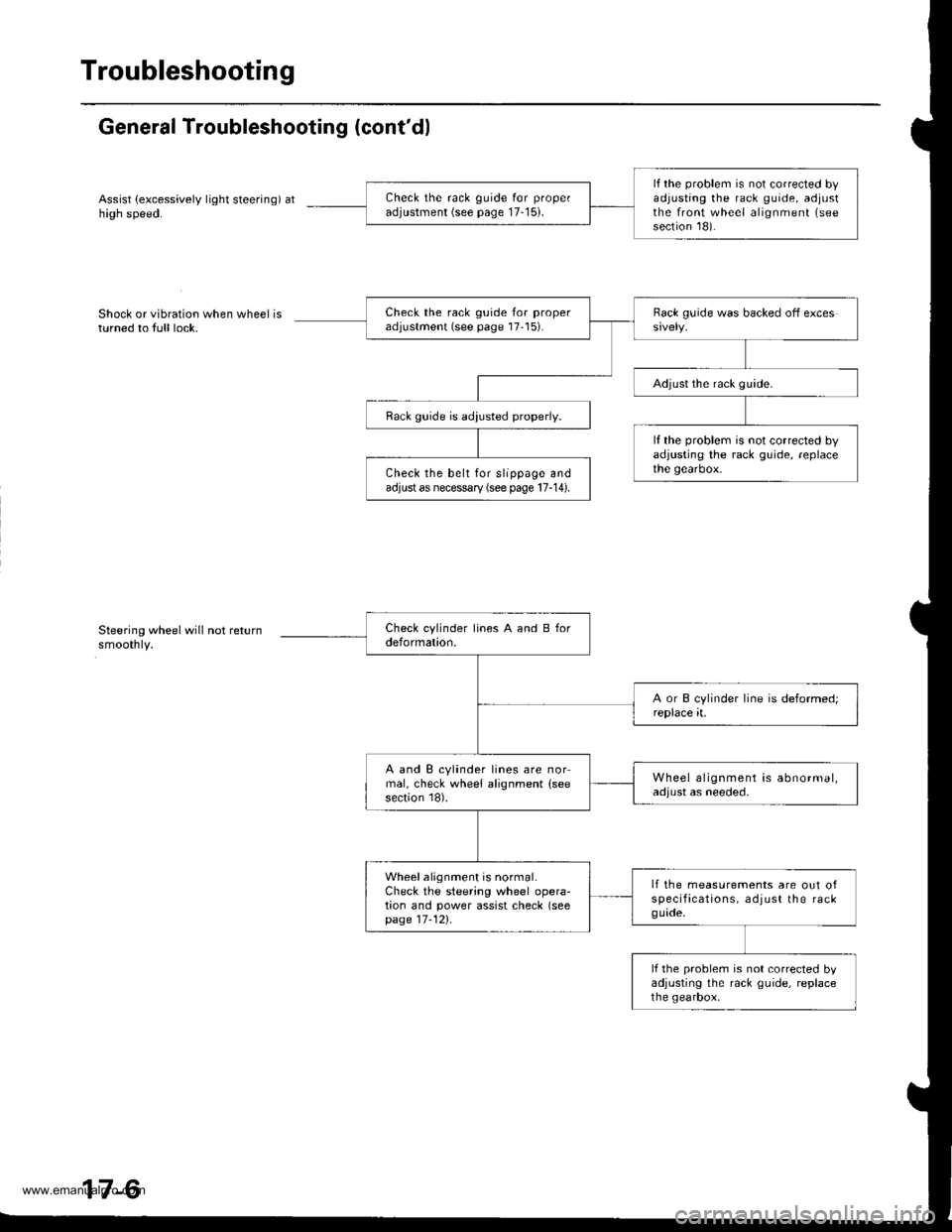
General Troubleshooting (cont'dl
Assist (excessively light steering) athigh speed.
Shock or vibration when wheel isturned to full lock.
Steering wheel will not returnsmoothly.
lf the problem is not corrected byadjusting the rack guide, adjustthe front wheel alignment (see
section 18).
Check the rack guide for proper
adjustment (see page 17-15).
Check the rack guide for properadjustment (see page 17'15).
Adjust the rack guide.
Rack guide is adiusted properly.
lf the problem is not corrected byadjusting the rack guide, replacethe gearbox.Check the belt for slippage andadjust as necessary (see page 17-14).
A and B cylinder lines are normal, check wheel alignment (see
section 18).
Wheel alignment is abnormal,adjust as needed.
Wheel alignment is normal.Check the steering wheel opera-tion and power assist check (seepage 17-121.
lf the measurements are out ofspecifacations, adjust the rackguade.
lf the problem is not corrected byadjusting the rack guide, replacethe gearbox,
www.emanualpro.com
Page 894 of 1395
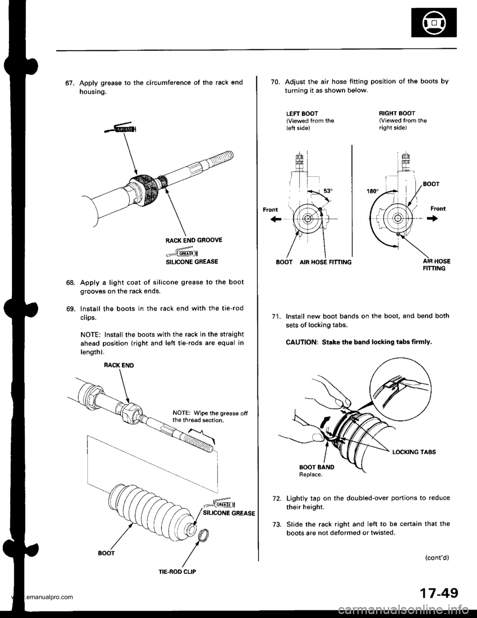
67. Apply grease to the circumference of the rack end
housing.
68.
69.
RACK END GROOVE
.={@
SILICONE GREASE
Apply a light coat of silicone grease to the boot
grooves on the rack ends.
lnstall the boots in the rack end with the tie-rod
clips.
NOTE: Install the boots with the rack in the straight
ahead position (right and left tie-rods are equal in
length).
RACK ENO
NOTE: Wipe the grease offthe thread section.
TIE.ROD CLIP
17-49
70. Adiust the air hose fitting position of the boots by
turning it as shown below.
LEFT BOOT{Viewed from theleft side)
+rom
''rT.a'.
, tri"
\,'tAr-
{,1@}tr
)Fr1
/\
RIGHT BOOT(Viewed trom theright side)
Front
+
BOOT AIR HOSE FITTING
71. Install new boot bands on the boot, and bend both
sets of locking tabs.
CAUTION: Stake the band locking tabs firmly.
Lightly tap on the doubled-over portions to reduce
their height.
Slide the rack right and left to be cenain that the
boots are not deformed or twisted.
(cont'd)
FIT'I'ING
www.emanualpro.com
Page 908 of 1395
Front Suspension
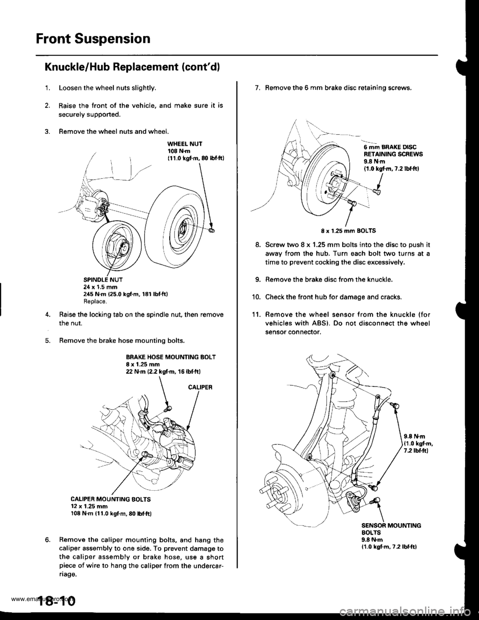
Knuckle/Hub Replacement (cont'dl
1.Loosen the wheel nuts slightly.
Raise the front of the vehicle, and make sure it is
secu.ely supported.
Remove the wheel nuts and wheel.
SPINDLE NUT24 x 1,5 mm245 N.m (25.0 kgf.m, 181 lbtft)Replace.
Raise the locking tab on the spindle nut, then remove
the nut.
Remove the brake hose mounting bolts.
BRAKE HOSE MOUNTING BOLT8 x 1.25 mm22 N.m {2.2 kgt m, 16 lbtft)
CALIPER MOUNTING BOLTS12 x 1.25 mm108 N.m (11.0 kgl.m, 80 lbl.ft)
Remove the caliper mounting bolts, and hang the
caliper assembly to ona side. To prevent damagg to
the caliper assembly or brake hose, use a shortpiece of wire to hang the caliper from the undercar-
riage.
18-10
7. Remove the 6 mm brake disc retaining screws,
6 mm BRAKE DISCRETAINING SCREWS9.8 N.m(1.0 kgl.m,7.2 lbf.ftl
8.
8 x 1.25 mm BOLTS
Screw two 8 x 1.25 mm bolts into the disc to push it
awav from the hub. Turn each bolt two turns at a
time to prevent cocking the disc excessively,
Remove the brake disc from the knuckle.
Check the front hub for damage and cracks.
11. Remove the wheel sensor from the knuckle (for
vehicles with ABS). Do not disconnect the wheel
sensor connector.
9.8 N.m(1.0 kgf.m,7.2 tbttrl
MOUNTINGBOLTS9.8 N.mlr.0 kgf.m, ?.2lbf.ftl
www.emanualpro.com
Page 929 of 1395
Brake Pedal
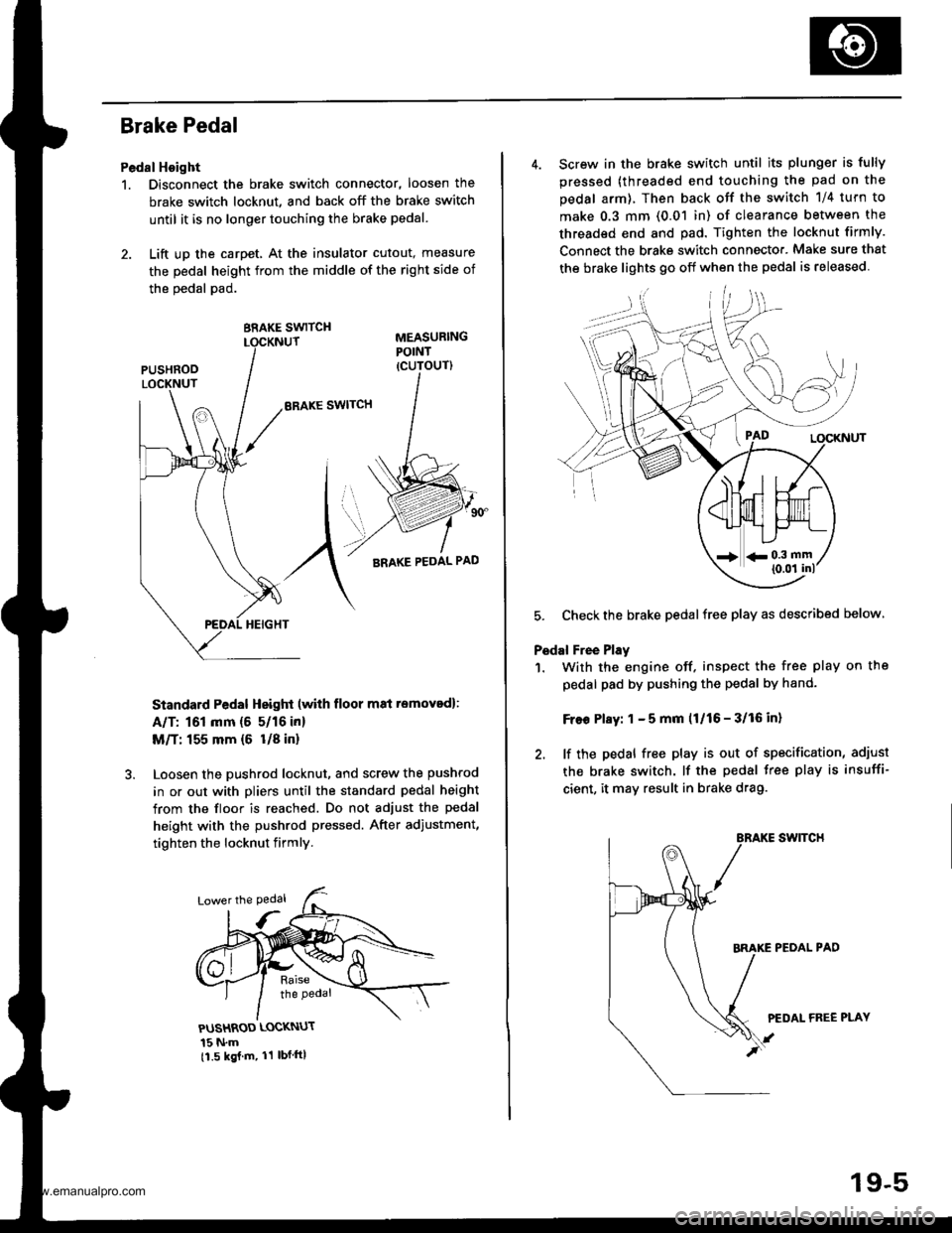
Pedal Hoight
1. Disconnect the brake switch connector, loosen the
brake switch locknut, and back off the brake switch
until it is no longer touching the brake pedal.
2. Lift up the carpet, At the insulator cutout, measure
the pedal height from the middle of the right side of
the oedal pad.
BRAKE SWITCH
ERAKE SWITCH
Standard Pedal Height (with floor m8i removed):
A/T: 161 mm (5 5/16 in)
M/T: 155 mm {6 U8 in}
Loosen the pushrod locknut, and screw the pushrod
in or out with pliers until the standard pedal height
from the floor is reached. Do not adjust the pedal
height with the pushrod pressed. After adiustment,
tighten the locknut firmly.
PUSHROD LOCKNUT
15 N.m11.5 kgj m, 11 lbf ftl
4. Screw in the brake switch until its plunger is fully
pressed (threaded end touching the pad on the
pedal arm), Then back otf the switch 1/4 turn to
make 0.3 mm (0.01 in) of clearance between the
threaded end and pad. Tighten the locknut firmly.
Connect the brake switch connecto.. Make sure that
the brake lights 90 off when the pedal is released
5. Checkthe brake pedalfree play as described below
Pedal Free Play
1. With the engine off. inspect the free play on the
pedal pad by pushing the pedal by hand-
Free Play: 1 - 5 mm (1/16 - 3/16 in)
2. lf the pedal free play is out of specification, adiust
the brake switch. lf the pedal free play is insuffi-
cient, it may result in brake drag.
swtTcH
PEOAL PAD
PEDAL FREE PLAY
19-5
www.emanualpro.com
Page 932 of 1395
![HONDA CR-V 1998 RD1-RD3 / 1.G Workshop Manual
Inspection and Adjustment
Brake System Indicator
Circuit Diagram lNuLR.HorJDGNrT 0llSt!ITCHUNDEB.DASHFUSE]NEtAY BOIrllA Nl] 42 4!A
PAF�K NC BRA(E S\IICH
GBNiBEO
Io\lt j I ERAKE tuU 0 rEVEr 9!1 I(N
| HONDA CR-V 1998 RD1-RD3 / 1.G Workshop Manual
Inspection and Adjustment
Brake System Indicator
Circuit Diagram lNuLR.HorJDGNrT 0llSt!ITCHUNDEB.DASHFUSE]NEtAY BOIrllA Nl] 42 4!A
PAF�K NC BRA(E S\IICH
GBNiBEO
Io\lt j I ERAKE tuU 0 rEVEr 9!1 I(N
|](/img/13/5778/w960_5778-931.png)
Inspection and Adjustment
Brake System Indicator
Circuit Diagram lNuLR.HorJDGNrT 0llSt!ITCHUNDEB.DASHFUSE]NEtAY BOIrllA Nl] 42 4!A
PAF�K NC BRA(E S\I'ICH
GBNiBEO
Io\lt j I ERAKE tuU 0 rEVEr 9!1 I(N
| oPt^r'f,'1 .r
BIKI-o-:G401
Parking Brake Switch Test
1. Remove the parking brake cover,
2. Disconnect the connector from the parking brakeswitch.
3. Check for continuity between the terminal and bodyground in each position according to the table.
Terminal
Lever Position \
Positive
TerminalBody Ground
Lever Up--o
Lever Down
NOTE (Canada): lf the parking brake switch is OK, butthe brake system indicator does not function, perform
the input test for the daytime running lights control unit(see section 23).
Brake Fluid Level Switch Test
1. Remove the reservoir cap. Check that the float
moves up and down freely; if it doesn't, replace the
reservoir cap assembly.
2. Check for continuity between the terminals in each
switch position according to the table.
- r9''r
Position12
FLOAT UP
FLOAT DOWNo
RESERVOIR CAP
GROUND
Switch contacts open atproper fluid level.
19-8
www.emanualpro.com
Page 933 of 1395
Front Brake Pads
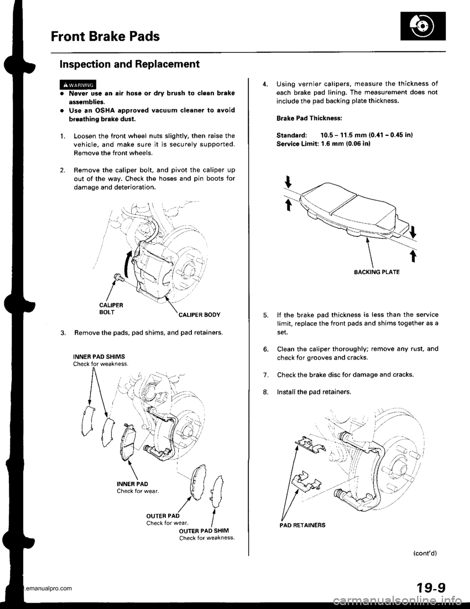
Inspection and Replacement
1.
Nsvgr u9e an air hose or dry brush to clean brake
assemblies.
Use an OSHA approved vacuum cleaner to avoid
broathing brake dust.
Loosen the front wheel nuts slightly, then raise the
vehicle, and make sure it is securely supported.
Remove the front wheels.
Remove the caliper bolt, and pivot the caliper up
out of the way. Check the hoses and pin boots for
damage and deterioration.
CALIPERBOLTCALIPER BODY
3. Remove the pads, pad shims, and pad retainers.
INNEB PAD SHIMSCheck for weakness.
#
IOUTER PAD SHIMCheck for weakness.
i)n.
4. Using vernier calipers, measure the thickness of
each brake pad lining. The measurement does not
include the pad backing plate thickness.
Brake Pad Thickness:
Standard: 10.5 - 11.5 mm {0.,11 - 0.45 in)
Servics Limit: 1.6 mm (0.06 in)
lf the brake pad thickness is less than the service
limit. replace the front pads and shims together as a
set.
Clean the caliper thoroughly; remove any rust, and
check for grooves and cracks.
Check the brake disc for damage and cracks.
Install the pad retainers.
7.
L
(cont'd)
19-9
EACKING PLATE
'.'..i
PAD RETAINERS
www.emanualpro.com
Page 935 of 1395
Front Brake Disc
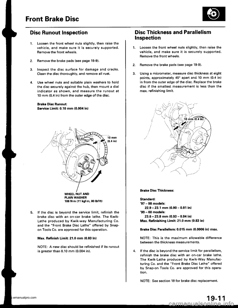
Disc Runout Inspection
l.Loosen the front wheel nuts slightly, then raise the
vehicle, and make sure it is securely supported.
Remove the front wheels.
Remove the brake pads {see page 19-9).
Inspect the disc surface for damage and cracks.
Clean the disc thoroughly, and remove all .ust.
Use wheel nuts and suitable plain washers to hold
the disc securely against the hub, then mount a dial
indicator as shown, and maasure the runout at
10 mm (0.4 in) from the outer edge of the disc.
Brake Di3c Runout:
Service Limit: 0.10 mm {0.00,0 in)
WHEEL NUT ANDPLAIN WASHER108 N.m {11 kg{ m, 80 lbf.ft)
lf the disc is beyond the service limit, refinish the
brake disc with an on-car brake lathe. The Kwik-
Lathe produced by Kwik-way Manufacturing Co.
and the "Front Brake Disc Lathe" offered by Snap-
on Tools Co. are approved for this operation.
M8x. Rofinish Limit: 21.0 mm l0.8il in)
NOTE: A new disc should bs refinished if its runout
is greater than 0.10 mm (0.004 in).
Disc Thickness and Parallelism
Inspection
1.Loosen the front wheel nuts slightly, then raise the
vehicle, and make sure it is securely supported.
Remove the front wheels.
Remove the brake pads (see page 19-9).
Using a micromater, measure disc thickness at eight
points, approximately 45'apan and 10 mm (0.4 in)
in from the outer edge of the disc. Replace the brake
disc if the smallest measurement is less than the
max. refinishing limit.
Brake Disc Thickness:
Standard:'97 - 98 modsls:
22.9 -23.1mm {0.90 - 0.91 inl'99 - 00 mod€ls:
23.6 - 23.8 mm {0.93 - 0.94 in}
Max. Refinishing Limit:21.0 mm (o.txl in)
Brake Disc Parallelism: 0.015 mm {0.0006 in} max.
NOTE: This is the maximum allowable difference
between the thickness measurements,
lf the disc is beyond the service limit for parallelism,
refinish the brake disc with an on-car brake lathe.
The Kwik-Lathe produced by Kwik-Way Manufac-
turing Co. and the "Front Brake Disc Lathe" offered
by Snap-on Tools Co. are approved for this opera-
tron.
NOTE: See section 18 for brake disc replacement.
19-1 1
www.emanualpro.com