light HONDA CR-V 1998 RD1-RD3 / 1.G Workshop Manual
[x] Cancel search | Manufacturer: HONDA, Model Year: 1998, Model line: CR-V, Model: HONDA CR-V 1998 RD1-RD3 / 1.GPages: 1395, PDF Size: 35.62 MB
Page 1016 of 1395
22.
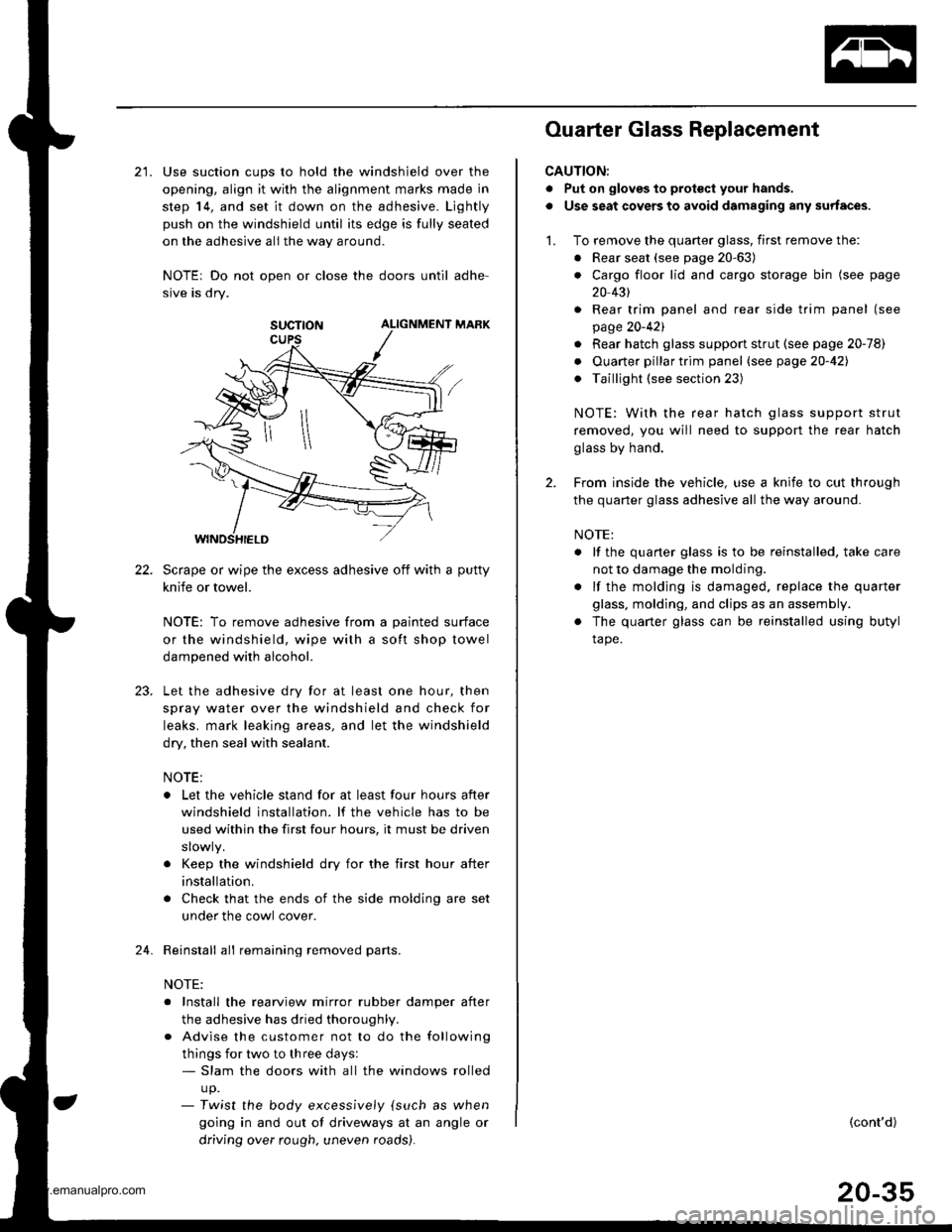
21. Use suction cups to hold the windshield over the
opening, align it with the alignment marks made in
step 14, and set it down on the adhesive. Ljghtly
push on the windshield until its edge is fully seated
on the adhesive all the way around.
NOTEr Do not open or close the doors until adhe-
sive is dry.
SUCTTON ALIGNMENT MARK
Scrape or wipe the excess adhesive off with a putty
knife or towel.
NOTE: To remove adhesive from a painted surface
or the windshield, wipe with a soft shop towel
dampened with alcohol.
Let the adhesive dry for at least one hour, then
spray water over the windshield and check for
leaks. mark leaking areas, and let the windshield
dry, then seal with sealant.
NOTE:
. Let the vehicle stand for at least four hours after
windshield installation. lf the vehicle has to be
used within the first four hours, it must be driven
. Keep the windshield dry for the first hour after
installation.
. Check that the ends of the side molding are set
under the cowl cover.
Reinstall all remaining removed parts.
NOTE:
. Install the rearview mirror rubber damper after
the adhesive has dried thoroughl,.
. Advise the customer not to do the following
things for two to three days:- Slam the doors with all the windows rolled
up.- Twist the body excess,vely {such as when
going in and out of driveways at an angle or
driving over rough. uneven roads).
24.
Ouarter Glass Replacement
CAUTION:
. Put on gloves to prot€ct your hands.
. Use seat covers to avoid damaging any surfaces.
1. To remove the quarter glass, first remove the:
. Rear seat (see page 20-63)
. Cargo floor lid and cargo storage bin (see page
20 431
. Rear trim panel and rear side trim panel (see
page 20-421
. Rear hatch glass support strut (see page 20-78)
. Ouarter pillar trim panel (see page20-421
. Taillight (see section 23)
NOTE: With the rear hatch glass support strut
removed, you will need to support the rear hatch
glass by hand.
2. From inside the vehicle, use a knife to cut through
the quarter glass adhesive all the way around.
NOTE:
. lf the quaner glass is to be reinstalled, take care
not to damage the molding.
. lf the molding is damaged. replace the quarter
glass, molding, and clips as an assembly.
. The quarter glass can be reinstalled using butyl
tape.
(cont'd)
20-35
www.emanualpro.com
Page 1018 of 1395
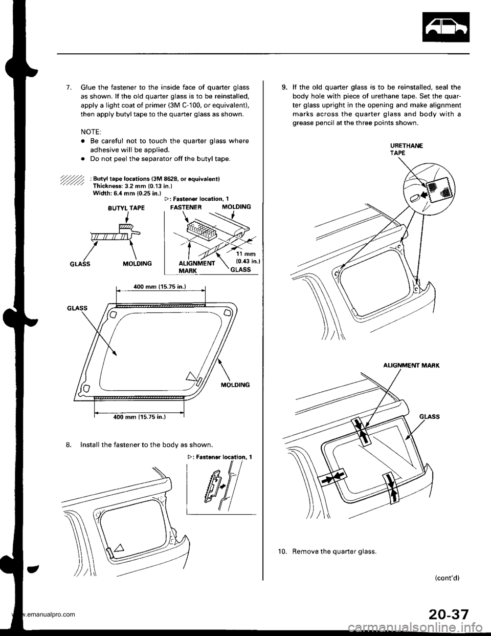
7. Glue the fastener to the inside face of quarter glass
as shown. lf the old quarter glass is to be reinstalled,
apply a light coat of primer (3M C- 100, or equivalent),
then apply butyltape to the quaner glass as shown.
NOTE:
. Be careful not to touch the quarter glass where
adhesive will be aDplied.
. Do not peel the separator off the butyl tape.
Width: 5.4 mm 10.25 in.)
BUTYL TAPE
I
w-mr
>t\
/\SS MOLDING
/'/.//// | Bttryl taee locations l3M 8628, or equivalent)Thickness:3.2 mm 10.13 in.l
>: Fastenoa location, I
FASTENER MOLDING
GLA
8. lnstall the fastener to the bodv as shown.
>: Fastener location, 1
1l mm(0.43 in.)
GLASS
400 mm (15.75 in.)
9. lf the old quarter glass is to be reinstalled, seal the
body hole with piece of urethane tape, Set the quar
ter glass upright in the opening and make alignment
marks across the quarter glass and body with a
grease pencil at the three points shown.
(cont'd)
20-37
ALIGNMENT MANK
10. Remove the quarter glass.
www.emanualpro.com
Page 1019 of 1395
Glass
Ouarter Glass Replacement (cont'd)
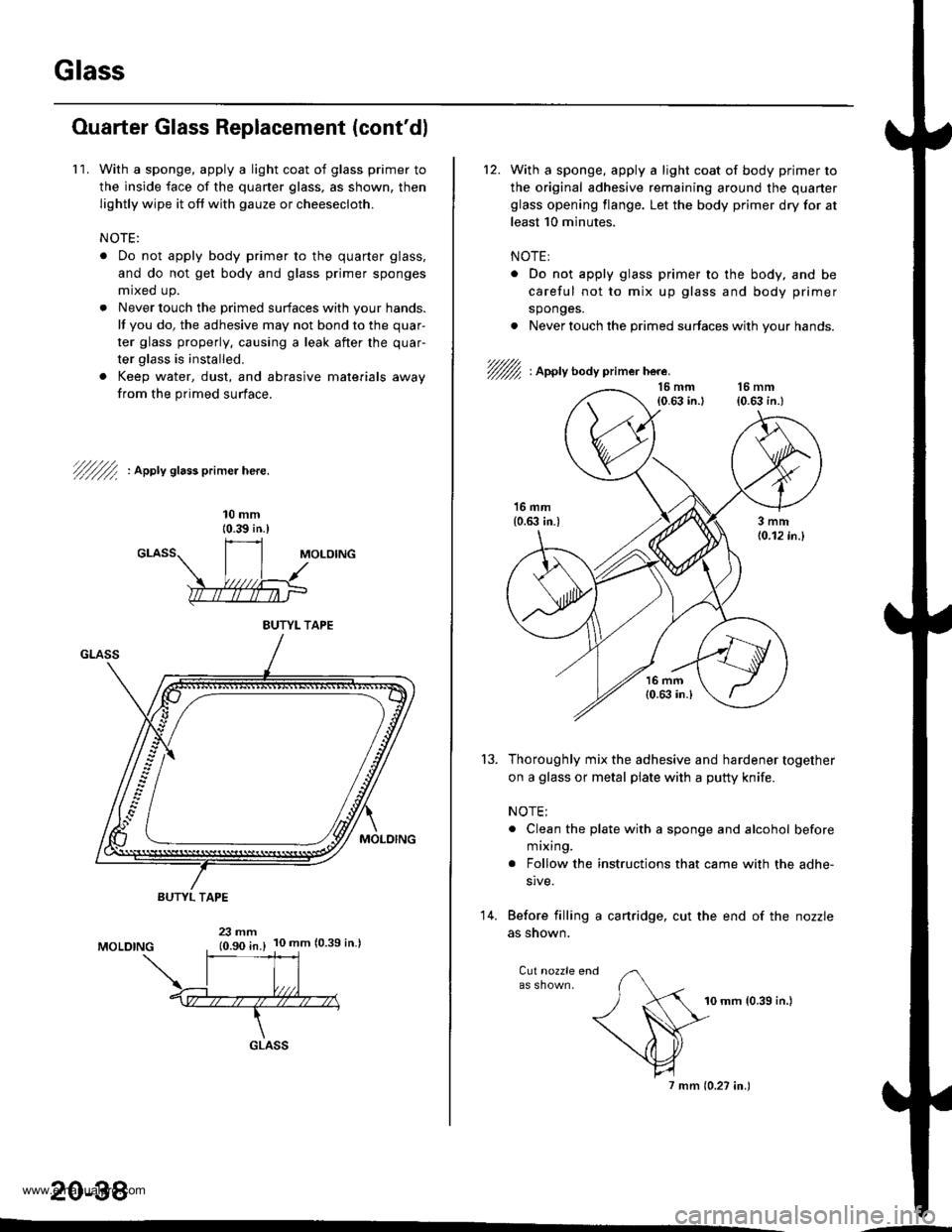
1 1. With a sponge, apply a light coat of glass primer to
the inside face of the quaner glass, as shown, then
lightly wipe it off with gauze or cheesecloth.
NOTE:
. Do not apply body primer to the quarter glass,
and do not get body and glass primer sponges
mrxed up.
. Never touch the primed surfaces with your hands.
It you do, the adhesive may not bond to the quar-
ter glass properly. causing a leak after the quar
ter glass is installed.
. Keep water, dust, and abrasive materials away
from the primed surface.
7///f ' aeery sra$ primer here.
10 mm{0.39 in.)
BUTYL TAPE
BUTYL TAPE
MOLOING23 mm10.90 in.)10 mm 10.39 in.)
GLASS
20-38
With a sponge, apply a light coat of body primer to
the original adhesive remaining around the quaner
glass opening flange. Let the body primer dry for at
least 10 minutes.
NOTE:
. Do not apply glass primer to the body, and be
careful not to mix up glass and body primer
sponges.
. Never touch the primed surfaces with your hands.
'/fu, : Apply body primer here.
'13.Thoroughly mix the adhesive and hardener together
on a glass or metal plate with a putty knife.
NOTE:
. Clean the plate with a sponge and alcohol before
m ixing.
. Follow the instructions that came with the adhe-
slve.
Before filling a cartridge, cut the end of the nozzle
as snown.
Cut nozzle end
10 mm {0.39 in.)
7 mm {0.27 in.)
14.
www.emanualpro.com
Page 1020 of 1395
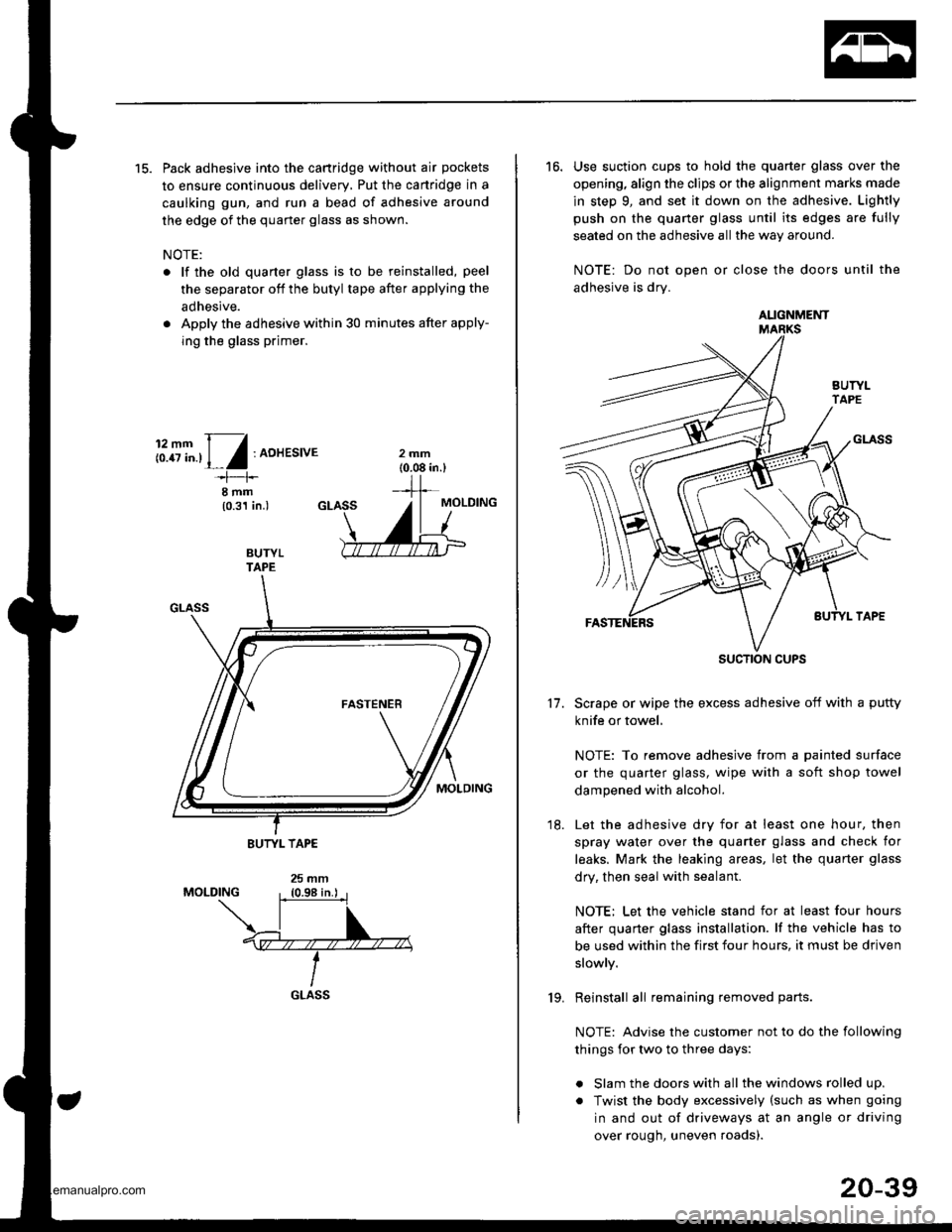
15. Pack adhesive into the cartridge without air pockets
to ensure continuous delivery, Put the canridge in a
caulking gun, and run a bead of adhesive around
the edge of the quarter glass as shown.
NOTE:
. lf the old quarter glass is to be reinstalled, peel
the separator off the butyl tape after applying the
adhesive.
. Apply the adhesive within 30 minutes after apply-
ing the glass primer.
i:.8T".,1,/:AoHEsrvE
I rnm(0.31 in.)
BUTYLTAPE
GLASS19.
20-39
16. Use suction cups to hold the quarter glass over the
opening, align the clips or the alignment marks made
in step 9, and set it down on the adhesive. Lightly
push on the quaner glass until its edges are fully
seated on the adhesive all the way around.
NOTE: Do not open or close the doors until the
adhesive is drv.
Scrape or wipe the excess adhesive off with a putty
knife or towel,
NOTE: To remove adhesive from a painted surface
or the quarter glass, wipe with a soft shop towel
dampened with alcohol.
Let the adhesive dry for at least one hour. then
spray water over the quarter glass and check for
leaks. Mark the leaking areas, let the quarter glass
dry, then seal with sealant.
NOTE: Let the vehicle stand for at least four hours
after quarter glass installation. lf the vehicle has to
be used within the first four hours, it must be driven
slowly.
Reinstall all remaining removed parts.
NOTE: Advise the customer not to do the following
things for two to three days:
. Slam the doors with all the windows rolled up.
. Twist the body excessively (such as when going
in and out of driveways at an angle or driving
over rough, uneven roads).
11.
18.
AUGNMENT
SUCTION CUPS
www.emanualpro.com
Page 1025 of 1395
lnterior Trim
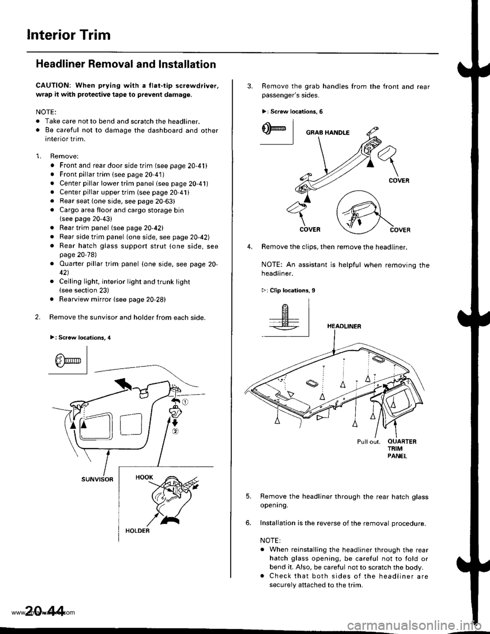
Headliner Removal and Installation
CAUTION: When prying with a tlat-tip screwdriver,
wrap it with protective tape to prevent damage.
NOTE:
. Take care not to bend and scratch the headliner.o Be careful not to damage the dashboard and other
interior trim.
1. Remove:
. Front and rear door side trim (see page 20-41). Front pillartrim (see page 20-41)
. Center pillar lower trim panel (see page 20-41). Center pillar upper trim (see page 20 41). Rear seat (one side, see page 20-63). Cargo area floor and cargo storage bin
{see page 20-43)
. Rear trim panel (see page 20-421
. Rear side trim panel (oneside, see page 20-42l,
. Rear hatch glass support strut (one side, seepage 20-78)
. Ouaner pillar trim panel {one side, see page 20-
42)
. Ceiling light, interior light and trunk light(see section 23)
. Rearview mirror (see page 20-28)
2. Remove the sunvisor and holder from each side.
>: Scaew location3, 4
I
A\"r- |Yr* || -
suNvtsoR
20-44
3. Remove the grab handles from
passenger's sides.
>r Screw locations, 6
the front and rear
ry_l
COVER
4. Remove the clips, then remove the headliner.
NOTE: An assistant is helpful when removing the
headliner.
>: Clip locations,9
HEADLINER
Pullout. OUARTERTRIMPANEL
5. Remove the headliner through the rear hatch glass
openrng.
6. Installation is the reverse of the removal procedure.
NOTE:
. When reinstalling the headliner through the rear
hatch glass opening, be careful not to fold or
bend it, Also, be careful not to scratch the body.. Check that both sides of the headliner are
securely attached to the trim.
www.emanualpro.com
Page 1055 of 1395
Bumpers
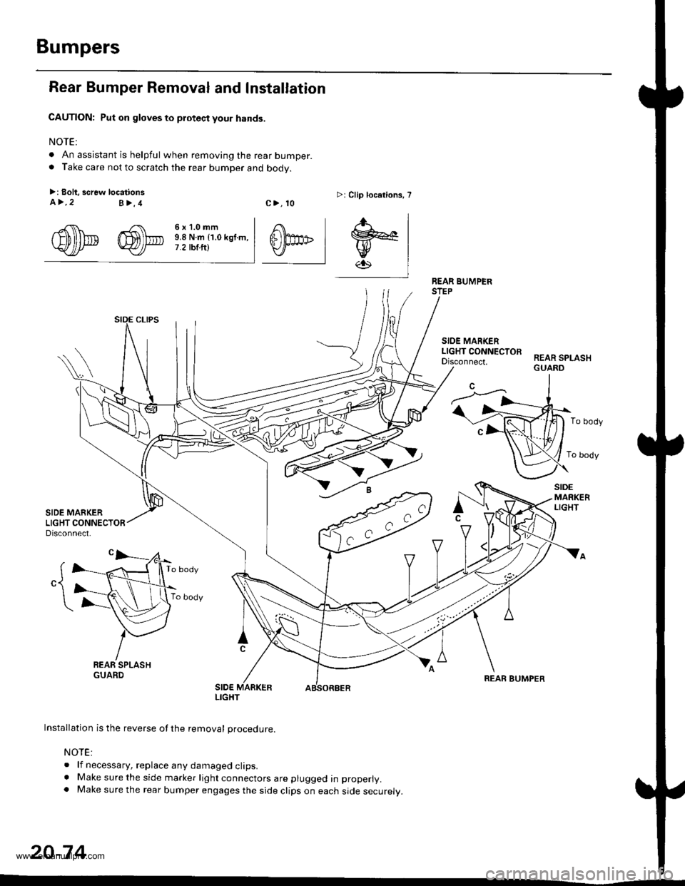
Rear Bumper Removal and Installation
CAUTION: Put on gloves to proteqt your hands.
NOTE:
. An assistant is helpful when removing the rear bumper.. Take care not to scratch the rear bumDer and bodv.
>: Boli, screw locationsa>,2B>,4c>, 10>: Clip locelions, 7
rgfi\\* ffi\\-. 3il;l-'lln*n,..,
WJ/* Y)f t.2tbtftl
.f-.' I
0f'" I trl-l.Kl
-l
BEAR BUMPERSTEP
SIOE MARKERLIGHT CONNECTOFDisconnect.REAR SPLASHGUARD
To body
To body
SIDEMARKERLIGHT
To body
To body
REAR BUMPER
Installation is the reverse of the removal procedure.
NOTE:
. lf necessary, replace any damaged clips.. Make sure the side marker light connectors are plugged in properly.. Make sure the rear bumper engages the side clips on each side securely.
20-74
LIGHT
www.emanualpro.com
Page 1057 of 1395
Hood
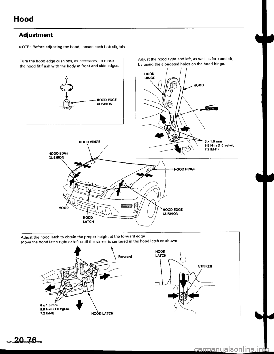
Adjustment
NOTE: Before adjusting the hood, loosen each bolt slightly.
Turn the hood edge cushions, as necessary, to make
the hood fit flush with the bodv at front and side edges.
f
sz
+
14---+ik-
HOOD EDGECUSHION
Adiust the hood latch to obtain the proper height at the forward edge'
Move the hood latch right or left until the striker is centered in the hood latch as shown
HOOD HINGE
\
?--
HOODLATCH
9.8 N.m (1.0 kgf m,
7.2 rbf.ftlHOOD LATCH
20-76
Adjust the hood right and left, as well as fore and aft,
by using the elongated holes on the hood hinge
6x1.0mm9.8 N.m (1.0 kgtm,7 .2 tbt.ttl
HOOD HINGE
www.emanualpro.com
Page 1060 of 1395
Disassembly and Reassembly
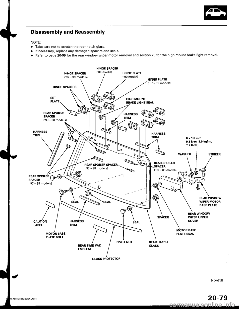
NOTE:
. Take care not to scratch the rear hatch glass.
. lf necessary, replace any damaged spacers and seals.
. Refer to page 20-99forthe rearwindowwiper motor removal and section 23 for the high mount brake light removal.
HINGE SPACERS
HINGE SPACEN('97 - 99 models)HINGE PLATE('00 model)
HARNESSTRIM
REAR SPOILEBSPACER{'99 00 models)
HARNESSTRIM6x1.0mm9.8 N.m {1.0 kgl.m,7.2 tbt.ft)
WASHERSTBIKER
s
R€AF WINDOWWIPER MOTORBASE PLATE
('97 - 98 models)
REAR SPOILERSPACER
CAUTIONLABEL
SEAL
REAR WINDOWWIPER UPPERCOVER
MOTOR BASEPLATE SEAL
PIVOT NUTFEAR TIME 4WDEMBLEM
{cont'd)
20-79
/=
GLASS PROTECTOR
www.emanualpro.com
Page 1062 of 1395
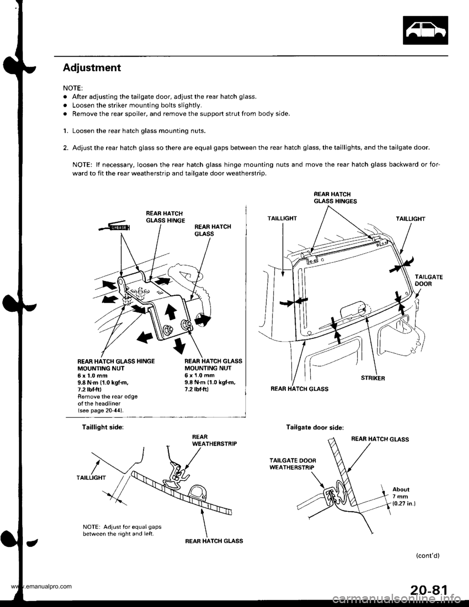
Adjustment
NOTE:
. After adjusting the tailgate door, adjust the rear hatch glass.
. Loosen the striker mounting bolts slightly.
. Remove the rear spoiler, and remove the support strut from body side.
1. Loosen the rear hatch glass mounting nuts.
2. Adjust the rear hatch glass so there are equal gaps between the rear hatch glass, the taillights, and the tailgate door.
NOTE: lf necessary, loosen the rear hatch glass hinge mounting nuts and move the rear hatch glass backward or for-
ward to fit the rear weatherstrip and tailgate door weatherstrip.
REAR HATCI{GLASS HINGES
REAR HATCH GLASS HINGEMOUNTING NUT6x1.0mm9.8 N.m (1.0 kgf.m,7.2 tbt f Remove the rear edgeotthe headliner(see page 20-44).
MOUNTING NUT6x1.0mm9.8 N.m 11.0 kgtm,7.2 rbf.ftt
Taillight side:Tailgate door side:
About7mm
1o.27 in.l
NOTE: Adjust for equal gapsbetween the right and left.TCH GLASSIHAREAR
(cont'd)
20-81
www.emanualpro.com
Page 1067 of 1395
Moldings
Door Moldings Replacement (cont'd)
It the old molding is to be reinstalled:
The following materials and tools are required to repair
the molding.
NOTE: Followthe manufacturer's instructions.
Materials: (Reference)
. Stripe remover
3M 08907
. Stripe adhesive remover
3M 08908
. Adhesive tape
3M Super Automotive Attachment Tape
Tools:
. Protective tape
. Knife or Cutter
. Sponge or Shop towel
. Infrared dryer
. Film
. Plastic putty knife
. Alcohol
CAUTION: Put on gloves to protect your hands,
1. lf necessary, replace any damaged clips on the mold-
ang.
2. Apply the stripe remover evenly to the bonding sur-
face of the body and molding.
3. Cover the bonding surface of the body and molding
with a film, then heat to 104 - 122"F (40 - 50'C) for 5- 10 minutes with an infrared dryer.
NOTE: Use care when heating to prevent deforma-
tion of the body and molding.
4. Carefully scrape the adhesive tape with a plastic
putty knife.
For removal of adhesive tape residue, follow-up with
stripe adhesive remover, then scrape the adhesive
tape with a plastic putty knife.
Remove the protective tape, then clean the bonding
surface with a sponge dampened in alcohol.
NOTE: Make sure the bonding surface is kept free or
water, oil and grease.
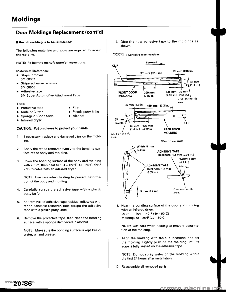
7. Glue the new adhesive tape
snown,
N : Adlesive tape locations
Forwerd L
820 mm 132.3 in.)
FRONTMOLDING
to the moldings as
25 mm {0.98 in.l
45 mm(1.8 in.l
200 mm(7.87 in.)
125 mm
{4.92 in.)30 mm
{1.2 in.}
t'.
Glue on the ribarea,26 mm (1.0 in.) 440 mm 117.3 in.l
35 mm 125 mm
{1.4 in.) {4.92 in.)REAR DOORMOLDING
(Front/rear end)
Width: 5 mm
Heat the bonding surface of the door and molding
with an infrared dryer.
Door: 104 - 140'F (40 - 60'C)
Molding: 68 - 86'F (20 - 30'C)
NOTE: Use care when heating to prevent deforma-
tion of the molding.
Align the molding with the clip locations, and set
the molding. Lightly push on the molding until its
edge is fully seated on the adhesive tape.
NOTE: Oo not spray water on the molding within
the first 24 hours after installation.
Reassemble all removed parts.10.
www.emanualpro.com