light HONDA CR-V 1998 RD1-RD3 / 1.G Workshop Manual
[x] Cancel search | Manufacturer: HONDA, Model Year: 1998, Model line: CR-V, Model: HONDA CR-V 1998 RD1-RD3 / 1.GPages: 1395, PDF Size: 35.62 MB
Page 650 of 1395
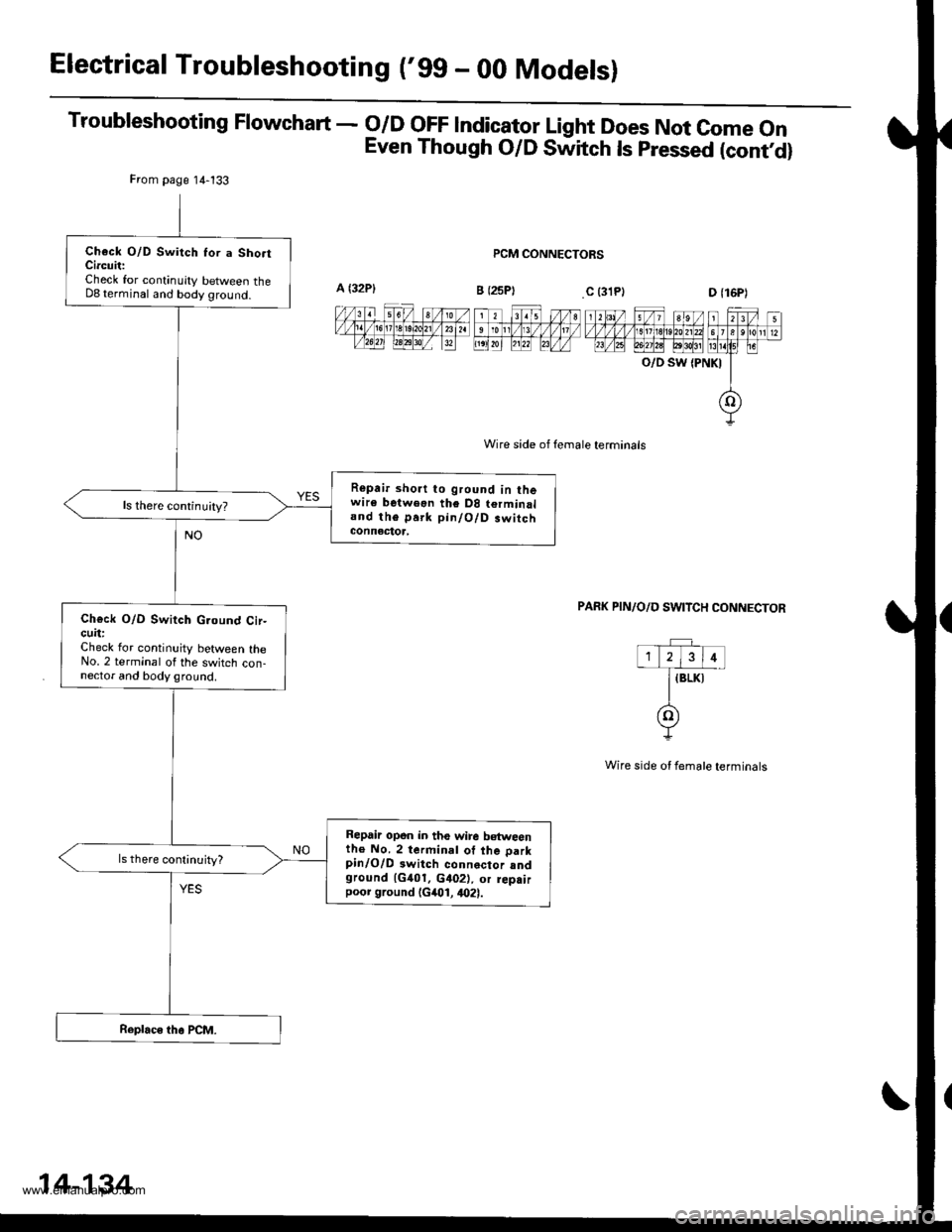
Electrical Troubleshooting ('gg - 00 Modelsl
Troubleshooting Flowchart - o/D oFF lndicator Light Does Not come on
Even Though O/D Switch ls pressed (contd)
PCM CONNECTORS
Wire side of female terminals
O/D SW {PNKI
PAFK PIN/O/D SWITCH CONNECTOR
Wire side ot female terminals
From page 14-133
Check O/D Switch Ior a Sho.tCircuit:Check for continuity between theD8 terminal and body ground.
Repair short to ground in thewire betweon the D8 terminaland the park pin/O/D.witchconnectoa,
ls there continuity?
Ch€ck O/D Switch G.ound Cir-cuit:Check lor continuity between theNo. 2 terminal of the switch con-nector and body ground.
Repair opon in the wire b€tweenth€ No. 2 terminal of the parkpinlO/D 3witch connector sndground 1G401. c402), or rep.irpoor ground (G401, 4021.
14-134
www.emanualpro.com
Page 657 of 1395
![HONDA CR-V 1998 RD1-RD3 / 1.G Workshop Manual
8. Set the control shaft to E] position. then install the
A,/T gear position switch on it.
CONTROL SHAFT
Install the AyT gear position switch cover and har-
ness clamp on the end cover.
Connect the HONDA CR-V 1998 RD1-RD3 / 1.G Workshop Manual
8. Set the control shaft to E] position. then install the
A,/T gear position switch on it.
CONTROL SHAFT
Install the AyT gear position switch cover and har-
ness clamp on the end cover.
Connect the](/img/13/5778/w960_5778-656.png)
8. Set the control shaft to E] position. then install the
A,/T gear position switch on it.
CONTROL SHAFT
Install the Ay'T gear position switch cover and har-
ness clamp on the end cover.
Connect the A,/T gear position switch connector.
then install it on the connector bracket.
Turn the ignition switch ON (ll). Move the shift lever
through all gears, and check the AfI gesr position
switch synchronization with the A/T gear position
indicator.
9.
10.
11.
A/TGEARPOSMON A/T GEAR POSITIONINDICATOR INDICATOR'99 - 00 MODELS '�97 - 98 MOOELS
12, Start the engine. Move the shift lever through all
gears. and verify the following:
. The shift lever cannot be moved to E] position
from E position unless the shift lever is pulled.
. The engine will not start in any position other
than E or E.. The back-up lights come on when the shift lever
is in El position.
14-141
www.emanualpro.com
Page 658 of 1395

A/T Gear Position Indicator
1.
f nput Test -'97 - 98 Models
Remove the gauge assembly from the dashboard (see section 20). and disconnect the 14P connector from the gauge
assemblv (see section 23),
Inspect the connector and socket terminals to be sure they are all making good contact.
. lf the terminals are bent, loose, or corroded, repairthem as necessary, and recheck the system.. lf the terminals look OK, make the following input tests at the 14P connector.- lf I test indicates a problem, find and correct the cause, then recheck the system.- lf all the input tests prove OK, but the indicator is faulty. replace the printed circuit board,
GAUGE ASSEMBLY 14P CONNECTOR
Wire side of female terminals
CavityWirs
ColorTest ConditionTest: Desir€d ResultPossible Cause
{lf rosult is not obtainod)
YEL
lgnition switch ON (ll)Check for voltage to ground:
There should be battery voltage,
. Blown No. 25 (7.5 A) fuse in the
under-dash fuse/relay box. An open in the wire
RE D/BLKCombination light
switch ON and dash
lights brightness con-
trol dial on full bright
Check for voltage between No. 2
and No. 3 terminals;
There should be battery voltage.
Blown No. 47 (7.5 A) fuse in the
under-dash fuse/relay box
Faulty combination Iight switch
Faulty dash iight brightness
controller
An open in the wire
RED
4BLUShift lever in ECheck for continuity to ground:
There should be continuity.
NOTE: There should be no continu-
ity in any other shift lever position.
' Faulty Ay'T gear position switch. An open in the wireBRNShift lever in E
7YELShift lever in @
8BLKUnder all conditionsCheck for continuity to ground:
There should be continuity
. Poor ground {G401). An open in the wire
9GRN/BLK
lgnition switch ON {ll)
and shift lever in any
position except E
Check for voltage to ground:
There should be battery voltage
for two seconds after the ignition
switch is turned ON {ll), and less
than 1 V two seconds later,
' Faulty PCM. An open in the wire
10GRNShift lever in ECheck for continuity to ground:
There should be continuity.
NOTE: There should be no conti-
nuity in any other shift lever posi-
UOn.
. Faulty A,ff gear position switch. An open in the wire1'lREDShift lever in @
12WHTShift lever in E
BLVBLU
Shift lever in ENOTE: Do not push
the brake pedal.
14LT GRN
lgnition switch ON { ll)
and shift lever in any
position except E and
E
Check for voltage to ground:
There should be about 5 V.
. Faulty PCM. An open in the wire
14-142
www.emanualpro.com
Page 659 of 1395

L
Input Test -'99 - 00 Models
Remove the gauge assembly from the dashboard {see section 20), and disconnect the 14P connector from the gauge
assembly (see section 23).
Inspect the connector and socket terminals to be sure they are all making good contact.
a lf the terminals are bent. loose, or corroded. repair them as necessary. and recheck the system.
. lf the terminals look OK, make the following input tests at the 14P connector.- lf a test indicates a problem, find and correct the cause, then recheck the system.- lf all the input tests prove OK, but the indicator is faulty, replace the printed circuit board.
GAUGE ASSEMBLY 14P CONNECTOR
Wire side of female terminals
CavityWire
ColorTest ConditionTest: Desired ResuhPossible Caus6
{lf resutt is not obtainod)
1YEL
lgnition switch ON (ll)Check for voltage to ground:
There should be battery voltage.
. Blown No.25 (7.5 A) fuse in the
under-dash fuse/relay box. An open in the wire
2RE D/BLK
Combination light
switch ON and dash
lights brightness con-
trol dial on full bright
Check for voltage between No. 2
and No.3 terminals:
There should be battery voltage.
Blown No. 47 {7.5 A) fuse in the
under-dash fuse/relay box
Faulty combination light switch
Faulty dash light brightness
controller
An open in the wire
5RED
BRNShift lever in ECheck for continuity to ground:
There should be continuity.
NOTE: There should be no continu-
ity in any other shift lever position.
. Faulty A/T gear position switch. An open in the wire7YELShift lever in E
'10BLUShift lever in E
LT BLU
lgnition switch ON (ll),
shift lever in E. and
Over-Drive is OFF bypressing O/D switch.
Check for continuity to ground:
There should be continuity.
Faulty O/D switch
Faulty A/T gear position switch
Faulty PCM
An open in the wire
8BLKUnder all conditionsCheck for continuity to ground:
There should be continuity
. Poor ground (G401)
. An open in the wire
9a:FI\|/Et| ta
lgnition switch ON (ll)
and shift lever in any
position except E
Check for voltage to groundl
There should be battery voltage
for two seconds after the ignition
switch is turned ON (ll). and less
than 1 V two seconds later.
. Faulty PCM. An open in the wire
11REDShift lever in SCheck for continuity to ground:
There should be continuity.
NOTE: There should be no conti-
nuity in any other shift lever posi-
Iton.
. Faulty A/T gear position switch. An open in the wire12WHTShift lever in E
BLI(BLU
Shift lever in ENOTE: Do not push
the brake pedal.
14LT GRN
lgnition switch ON (ll)
and shift lever in any
position except E and
E
Check for voltage to groundl
There should be about 5 V,
. Faulty PCM. An open in the wire
14-143
www.emanualpro.com
Page 669 of 1395
Symptom-to-Component Chart
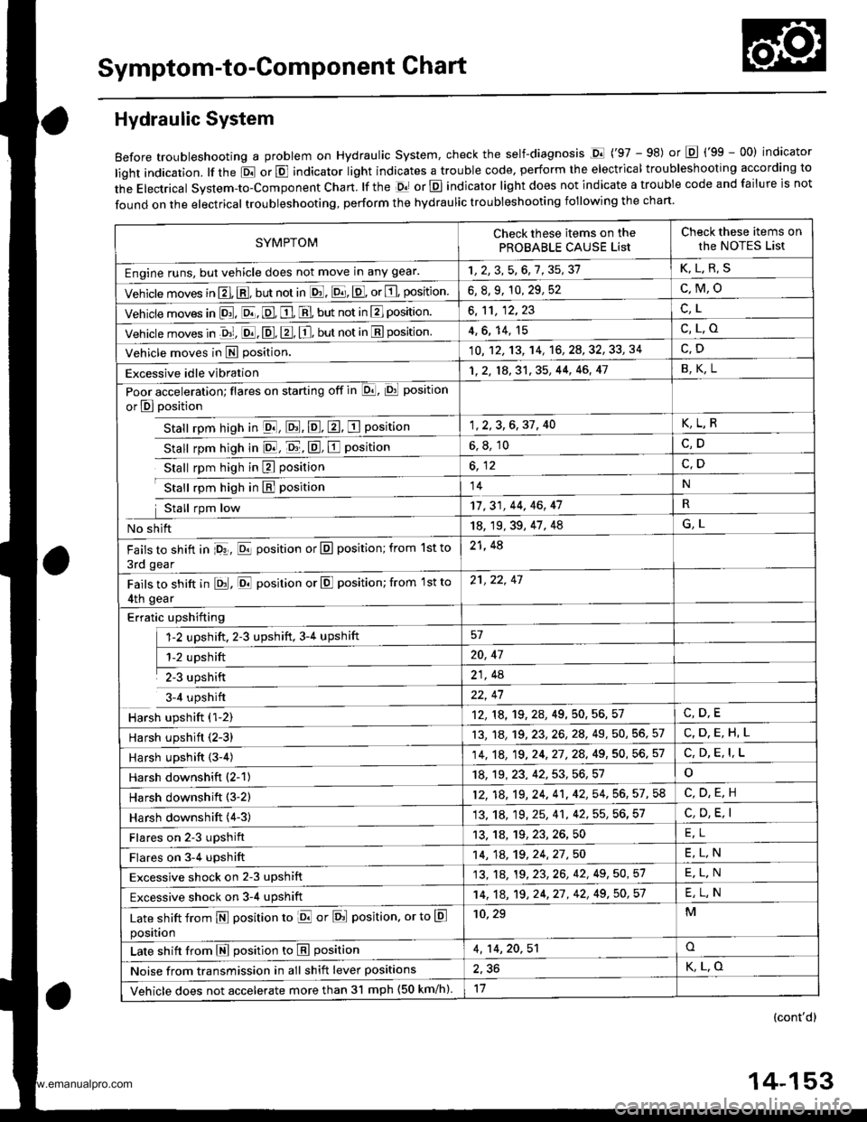
Hydraulic System
Before troubleshooting a problem on Hydraulic system, check the self-diagnosis Dl ('97 - 98) or Lq ('99 - 00) indicator
light indication. lf the El or E indicator light indicates a trouble code, perform the electrical troubleshooting according to
the Electrical System-to-Component Chart. lf the Ol or E indicator light does not indicate a trouble code and failure is not
found on the electrical troubleshooting, perform the hydraulic troubleshooting following the chart.
SYMPTOMCheck these items on the
PROBABLE CAUSE List
Check these items on
the NOTES List
Engine runs, but vehicle does not move in any gear.1r2FAt?82?K,L.R,S
Vehicle moves in El. @, but not in lE. E, E, or E, position6, 8, 9, 10, 29, 52c,M,o
Vehicle moves in [D!. E, E. E, E, but not in E] position.al
Vehicle moves in .&1, E. E, E, E, but not in E position4,6, 14, 15c,L.o
Vehicle moves in E position.10 , 12, 13, '�l4, '16, 2A, 32, 33, 34
Excessive idle vibration1,2, 18,3'1,35, 44, 46, 41B,K,L
Poor acceleration; flares on starting off in E, Di position
or E position
Stall rpm hish in El, El, E, E, E Position
Stall rpm hiqh in E, E, E, E position
1,2,3,6,37, 40K,L,R
6, 8, 10C,D
Stall rpm high in E positionc,D
Stall rpm high in hl position14N
Stall rpm low17,31, 44, 46, 47R
No shift18, 19, 39, 47, 48G,L
Fails to shift in Pr, E position or E position; from 1st to
3rd gear
21, 48
Fails to shift in EJ, E position or E position; from 1st to
4th gear
21,22, 47
Erratic upshifting
fz upshlft. ,3 ripshlft, 3r. up+ilft57
ffi20, 47
il21, 4A
3-4 upshift22, 47
Harsh upshift ('l-2)12, 18, 19,2A,49, 50, 56, 57
Harsh upshift (2-3)13, 1A, 19,23,26,28, 49, 50, 56, 57C,D.E,H,L
Harsh upshift {3-4)14,1A, 19,24,27,28, 49, 50, 56. 57C, D, E, I,L
Harsh downshitt (2-1)18, 19,23, 42,53,56,51o
Harsh downshift (3-2)12, 18,19,24,41,42, 54. 56, 57, 58
Harsh downshift (4-3)13,'1A, 19, 25, 41, 42, 55, 56, 57C, D, E, I
Flares on 2-3 upshift13,1A,19,23,26,50FI
Flares on 3-4 upshift14, 1A, 19,24,27,50E,L,N
Excessive shock on 2-3 upshift13. '18, 19 , 23, 26, 42, 49 , 50, 51E.L.N
Excessive shock on 3-4 upshift14, 1A, 19,24,27 , 42, 49,50,51E,L,N
Late shift from N position to ld or Erl position. or to E
position
10, 29M
Late shift from E position to E position4, 14,20,51o
Noise from transmission in all shift lever positions2,36K,L.O
Vehicle does not accelerate more than 3l mph (50 km/h).11
(cont'd)
14-153
www.emanualpro.com
Page 679 of 1395
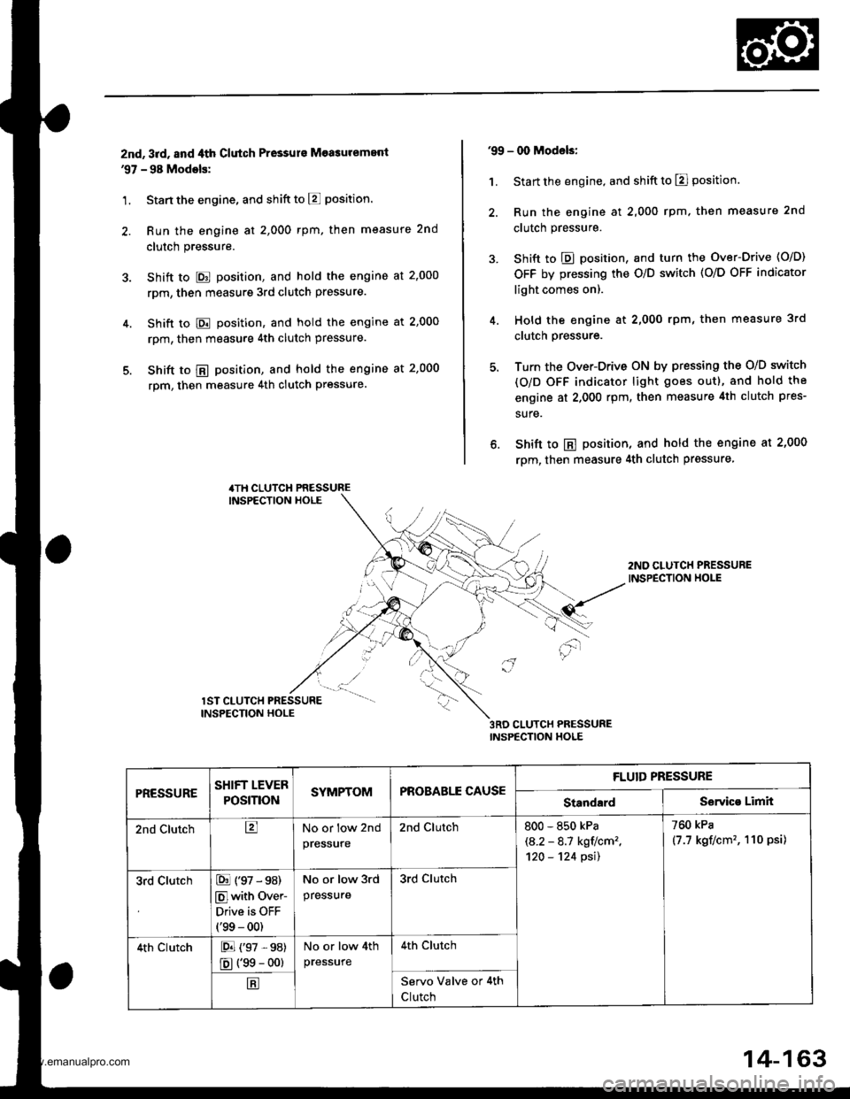
znd, 3rd, and ,lth Clutch Pressurs Measuremenl'97 - 98 Modols:
1. Stan the engine, and shift to E position.
2. Run the engine at 2,000 rpm, then measure 2nd
clutch pressure.
3. Shift to E position, and hold the engine at 2'000
rpm, then measure 3rd clutch pressure.
4. Shift to E position, and hold the engine at 2,000
rpm, then measure 4th clutch pressure.
5. Shift to @ position, and hold the engine at 2,000
rpm, then measure 4th clutch pressure.
4TH CLUTCH PRESSUREINSPECTION HOLE
'99 - 00 Models:
1. Start the engine, and shift to El position.
2. Run the engine at 2,000 rpm. then measure 2nd
clutch pressure.
3. Shift to E position, and turn the Over-Drive (O/D)
OFF by pressing the O/D switch (O/O OFF indicator
light comes on).
4. Hold the engine at 2,000 rpm, then measure 3rd
clutch Pressure.
5. Turn the Over-Drive ON by pressing the O/D switch
(O/D OFF indicator light goes out), and hold the
engine at 2,000 rpm, then measure 4th clutch pres-
sure.
6. Shift to E position, and hold the engine at 2,000
rpm, then measure 4th clutch prgssure
2ND CLUTCH PRESSUREINSPECTION HOLE
3RD CLUTCH PRESSUREINSPECTION HOLE
'"r.,-ur"" "..#
- -t"1' -.
INSPECTION HOLE
PRESSURESHIFT LEVER
POSmONSYMPTOMPROBABLE CAUSE
FLUID PRESSURE
StandardServico Limit
2nd ClutchtrNo or low 2nd
pres$ure
2nd Clutch800 - 850 kPa
\A.2 - 8.1 kgtlcm2,'120 - '124 psil
760 kPa
(7.7 kgf/cm'�, 110 psi)
3rd ClutchE (97 - s8)
Elwith Over-
Drive is OFF(99 - 00)
No or low 3rd
pressure
3rd clutch
4th clutchE (97 ,98)
E (99 - oo)
No or low 4th
pressure
4th Clutch
EServo Valve or 4th
Clutch
14-163
www.emanualpro.com
Page 708 of 1395
Valve Body
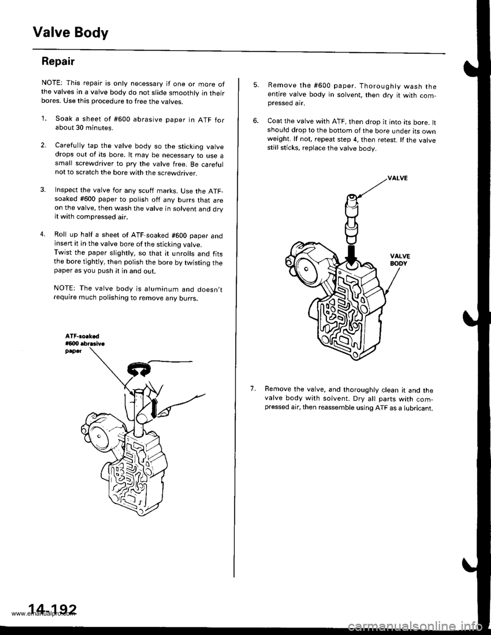
Repair
NOTE: This repair is only necessary if one or more ofthe valves in a valve body do not slide smoothly in theirbores. Use this procedure to free the varves.
'1. Soak a sheet of #600 abrasive paper in ATF forabout 30 minutes.
2. Carelully tap the valve body so the sticking valvedrops out of its bore. lt may be necessary to use asmall screwdriver to pry the valve free. Be carefulnot to scratch the bore with the screwdriver.
4.
Inspect the valve for any scutf marks. Use the ATF-soaked #600 paper to polish off any burrs that areon the valve, then wash the valve in solvent and dryit with compressed air.
Roll up half a sheet of ATF-soaked #600 paper andinsert it in the valve bore of the sticking valve.Twist the paper slightly, so that it unrolls and fitsthe bore tightly, then polish the bore by twisting thepaper as you push it in and out.
NOTE: The valve body is aluminum and doesn,trequire much polishing to remove any ourrs.
,l
14-192
5.Remove the #600 paper. Thoroughly wash theentire valve body in solvent, then dry it with com-pressed ar.
Coat the valve with ATF, then drop it into its bore, ltshould drop to the bottom of the bore under its ownweight. lf not, repeat step 4, then retest. lf the valvestill sticks, replace the valve body.
Remove the valve. and thoroughly clean it and thevalve body with solvent. DrV all parts with com-pressed air, then reassemble using ATF as a lubricant.
1.
w
www.emanualpro.com
Page 720 of 1395
MainshaftSealing Rings
Inspection (cont'dl
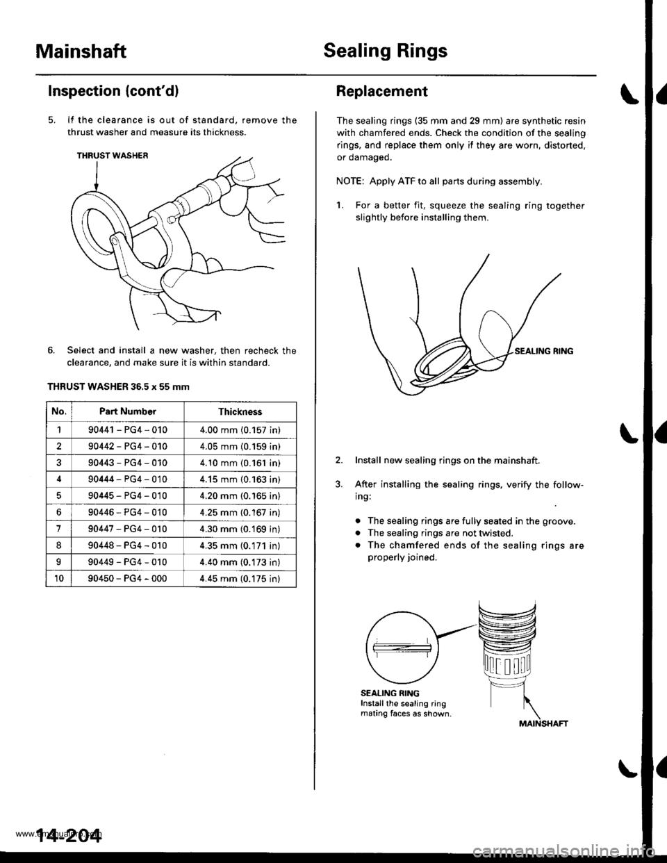
It the clearance is out of standard, remove the
thrust washer and measure its thickness.
Select and install a new washer, then recheck the
clearance, and make sure it is within standard.
THRUST WASHER 36.5 x 55 mm
No.Part NumberThickness
190441 - PG4,0104.00 mm (0.157 in)
290442-PG4-0104.05 mm (0.159 in)
90443-PG4-0104.10 mm {0.161 in)
90444-PG4-0104.15 mm {0.163 in)
90445-PG4-0104.20 mm (0.'165 in)
690446-PG4-0104.25 mm {0.167 in)
190447-PG4-0104.30 mm (0.169 in)
890448-PG4-0104.35 mm (0.171 in)
I90449-PG4-0104.40 mm (0.173 in)
1090450-PG4-0004.45 mm (0.175 inl
14-204
Replacement
The sealing rings (35 mm and 29 mm) are synthetic resin
with chamfered ends. Check the condition of the sealing
rings, and replace them only if they are worn, distorted,
or oamageo.
NOTE: Apply ATF to all partsduring assembly.
1. For a better fit, squeeze the sealing ring together
slightly before installing them.
Install new sealing rings on the mainshaft.
After installing the sealing rings, verify the follow-
ing:
. The sealing rings are fully seated in the groove.
. The sealing rings are not twisted.
. The chamfered ends of the sealing rings are
properly joined.
SEALING RINGInstall the sealing ringmating faces as shown.
www.emanualpro.com
Page 750 of 1395
Transfer Assembly
Inspection
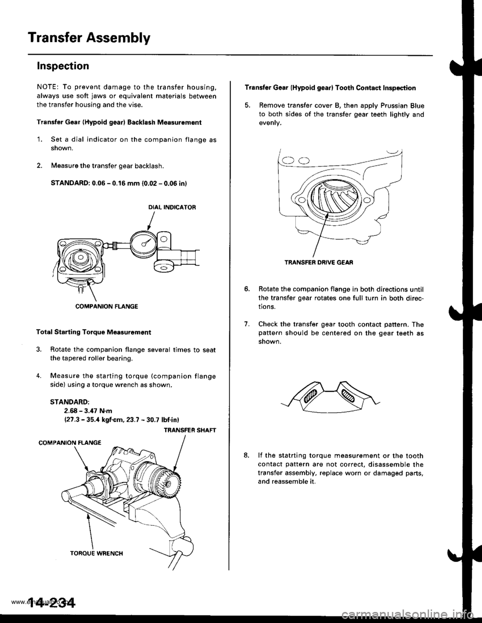
NOTE: To prevent damage to the transfer housing,
always use soft jaws or equivalent materials between
the transfer housing and the vise.
Trsnsfer Gear (Hypoid gear) Backl8sh M€asurem€nt
1. Set a dial indicator on the companion flange as
snown.
2. Measure the transfer gear backlash.
STANDARD: 0.06 - 0.16 mm {0.02 - 0.06 in)
Total Starting Torque Meagurgm€nt
3, Rotate the companion flange several times to seat
the tapered roller bearing.
4. Measure the starting torque (companion flange
side) using a torque wrench as shown,
STANDARD:
2.68 - 3.,17 N.m(27.3 - 35.,1 kgf.cm, 23.7 - 30.7 lbf.inl
TRANSFER SHAFT
DIAL INDICATOR
COMPANION FLANGE
14-234
Transfer Gear (Hypoid gear) Tooth Contact Inspection
5, Remove transfer cover B, then apply Prussian Blue
to both sides of the transfer gear teeth lightly and
Rotate the companion flange in both directions until
the transfer gear rotates one full turn in both direc-
tions.
Check the transfer gear tooth contact pattern. Thepattern should be centered on the gear tseth as
snown.
6.
7.
8.lf the statrting torque measurement or the tooth
contact pattern are not correct, disassemble the
transfer assembly, replace worn or damaged parts,
and reassemble it.
TRANSFER DRIVE G€AR
www.emanualpro.com
Page 760 of 1395
Transfer Assembly
18.
Reassembly (cont'dl
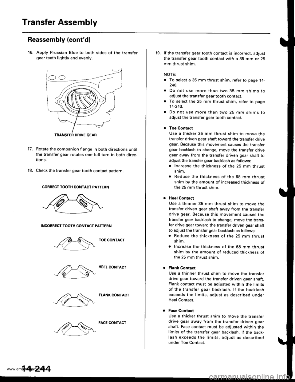
16. Apply Prussian Blue to both sides of the transfergear teeth lightly and evenly.
17.Rotate the companion flange in both directions until
the transfer gear rotates one full turn in both direc-
tions.
Check the transfer gear tooth contact pattern.
CORRECT TOOTH CONTACT PATTERN
NCONRECT TOOTH CONTACT PATTERN
TOE CONTACT
HEEL CONTACT
FLANK CONTACT
14-244
FACE CONTACT
19. lf the transfer gear tooth contact is incorrect, adjust
the transfer gear tooth contact with a 35 mm or 25
mm th rust shim.
NOTE:
. To select a 35 mm thrust shim, refer to page 14,240.
. Do not use more than two 35 mm shims to
adjust the transfer gear tooth contact.. To select the 25 mm thrust shim, refer to page
14-243.
. Do not use more than two 25 mm shims to
adjust the transfer gear tooth contact.
Toe Contact
Use a thicker 35 mm thrust shim to move the
transfer driven gear shaft toward the transfer drivegear. Because this movement causes the transfergear backlash to change, move the transfer drivegear away from the transfer driven gear shaft to
adjust the transfer gear backlash as follows:. Increase the thickness of the 25 mm thrust
shrm.
. Reduce the thickness of the 68 mm thrust
shim by the amount of increased thickness of
the 25 mm thrust shim.
Heel Contact
Use a thinner 35 mm thrust shim to move the
transfer driven gear shaft away from the transfer
drive gear. Because thjs movement causes the
transfer gear backlash to change, move the trans-
fer drive gear toward the transfer driven gear shaft
to adjust the transfer gear backlash as follows:. Reduce the thickness of the 25 mm thrust
shim.
. Increase the thickness of the 68 mm thrust
shim by the amount of reduced thickness ofthe 25 mm thrust shim.
Flank Contaqt
Use a thinner thrust shim to move the transfer
drive gear toward the transfer driven gear shaft.Flank contact must be adjusted within the limits
of the transfer gear backlash. lf the backlash
exceeds the limits, adjust as described underHeel Contact.
Face Contaqt
Use a thicker thrust shim to move the transfer
drive gear away from the transfer driven gear
shaft. Face contact must be adjusted within the
limits of the transfer gear backlash. lf the back-
lash exceeds the limits, adjust as described
under Toe Contact.
www.emanualpro.com