clutch HONDA CR-V 1998 RD1-RD3 / 1.G Workshop Manual
[x] Cancel search | Manufacturer: HONDA, Model Year: 1998, Model line: CR-V, Model: HONDA CR-V 1998 RD1-RD3 / 1.GPages: 1395, PDF Size: 35.62 MB
Page 1155 of 1395
Clutch Inspection
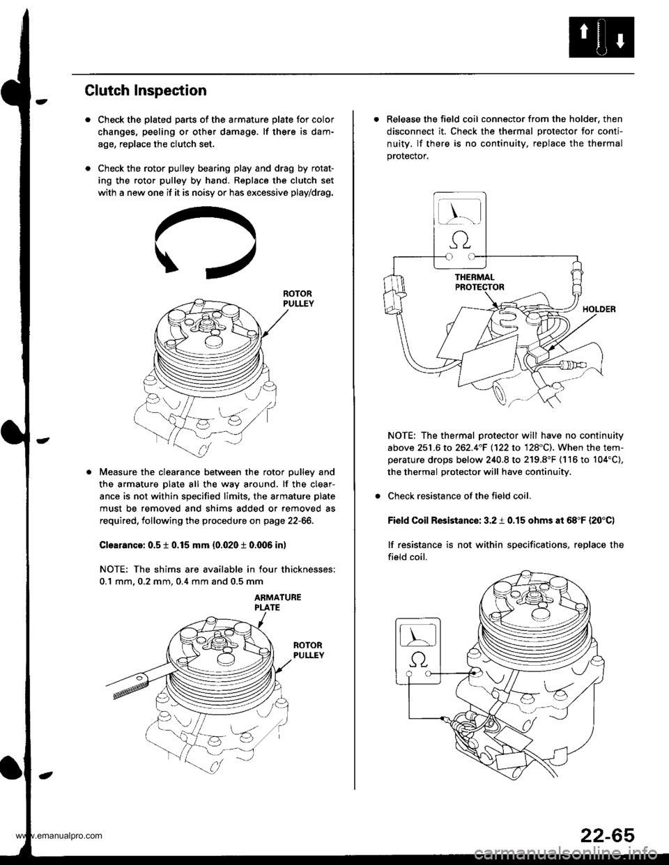
Check the plated parts of the armature plate for color
changes, peeling or other damage. lf there is dam-
age, replace the clutch set.
Check the rotor pulley bearing play and drag by rotat-
ing the rotor pulley by hand. Replace the clutch set
with a new one if it is noisy or has excessive play/drag.
Measure the clearance between the rotor pulley and
the armature plate all the way around. lf the clear-
ance is not within specified limits, the armature plate
must be removed and shims added or removed as
required, following the procedure on page 22-66.
Cloarance: 0.5 t 0.15 mm {0.020 t 0.q)6 in)
NOTE: The shims are available in four thicknesses:
0.1 mm. 0.2 mm. 0.4 mm and 0.5 mm
ABMATUBE
ROTOR
. Release the field coil connector from the holder, then
disconnect it. Check the thermal protector for conti-
nuity, lf there is no continuity, replace the thermal
prorecror.
NOTE: The thermal protector will have no continuity
above 251.6 to 262.4"F 1122 to 128"C). When the tem-perature drops below 240.8 to 219.8"F (116 to 104'C),
the thermal protector will have continuity.
Check resistance of the field coil.
Field Coil Resistance: 3.2 i 0.15 ohms at 68"F {20'C)
lf resistance is not within specifications, replace the
field coil.
22-65
www.emanualpro.com
Page 1156 of 1395
Compressor
Glutch Overhaul
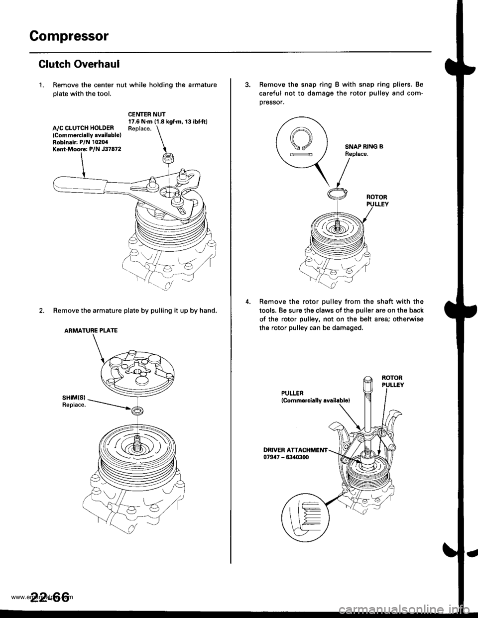
1. Remove the center nut while holding the armature
plate with the tool.
A,/C CLUTCH HOLOERlCommerciallY .vailable)Robinair: P/N 1020,0Ked-Mooro: P/N J37872
CENTER NUT17.6 N.m ('1.8 kgf.m, 13lbfft)Reolace. \
i
2. Remove the armature plate by pulling it up by hand.
ARMATURE PLATE
sHtMls)Replace.
za:s
(i@,
22-66
3. Remove the snap ring B with snap ring pliers. Be
careful not to d8mage the rotor pulley and com-
pressor.
SNAP RING BR6place.
Remove the rotor pulley from the shaft with the
tools. Be sure the claws ot the puller are on the back
of the rotor pulley, not on the belt area; otherwise
the rotor pulley can be damaged.
www.emanualpro.com
Page 1157 of 1395
l-
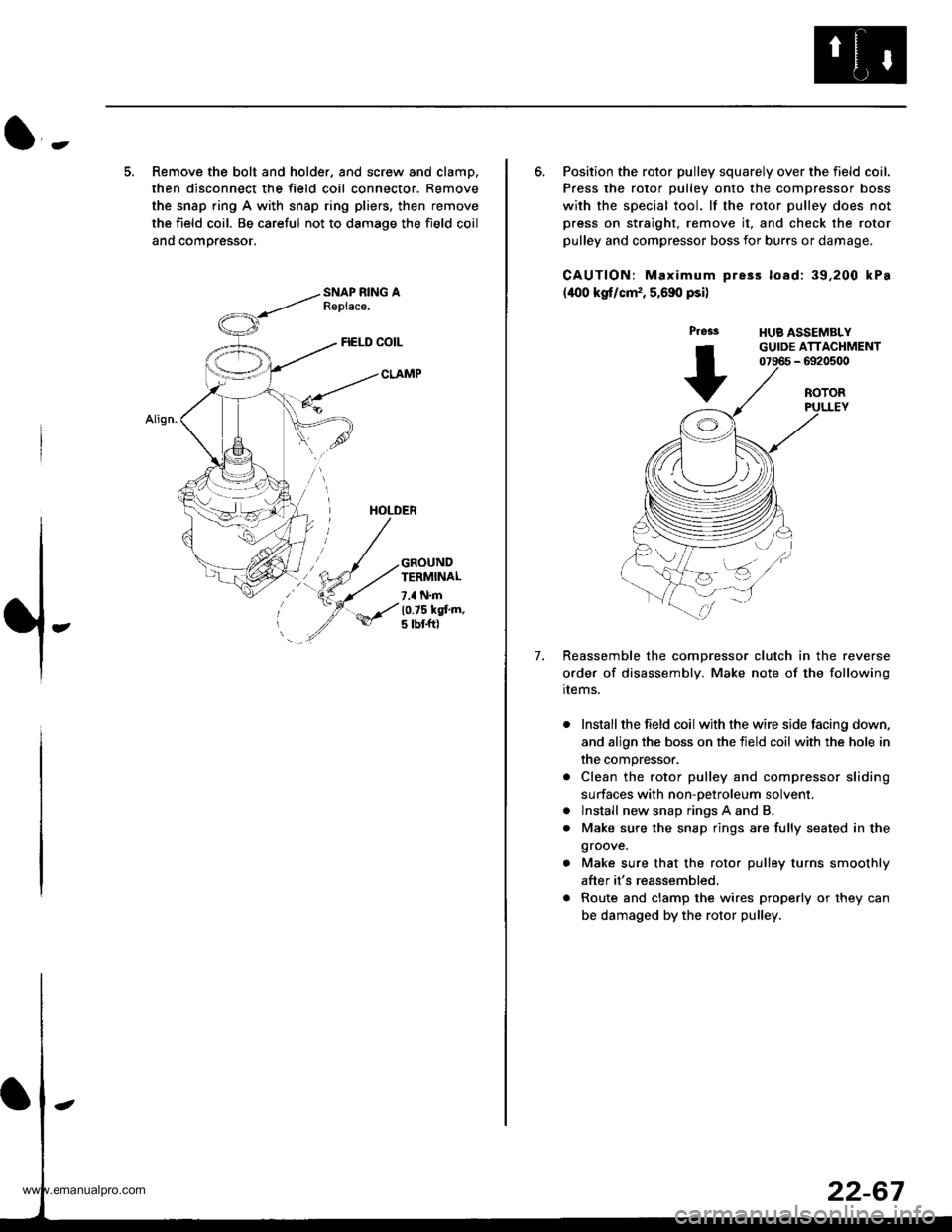
5. Remove the bolt and holder, and screw and clamp.
then disconnect the field coil connector. Remove
the snap ring A with snap ring pliers, then remove
the field coil. Be careful not to damage the field coil
and comoressor.
FIELD COIL
CLAMP
HOLDER
GROUNDTERMINAL
7,a N.m
10.75 kgt'm,5 tbt ftl
6. Position the rotor pulley squarely over the field coil.
Press the rotor pulley onto the compressor boss
with the special tool. lf the rotor pulley does not
press on straight, remove it, and check the rotor
pulley and compressor boss for burrs or damage.
CAUTION: Maximum pre3s load: 39,200 kPa
(400 kgf/cm,, 5,690 psi)
Press
+
HUB ASSEMBLYGUIDE ATTACHMENT07966 - 6920500
7.
ROTORPULLEY
Reassemble the comDressor clutch in the reverse
order of disassembly. Make note of the following
rrems.
Install the field coil with the wire side facing down,
and align the boss on the tield coil with the hole in
the compressor.
Clean the rotor pulley and compressor sliding
surfaces with non-oetroleum solvent.
lnstall new snap rings A and B.
Make sure the snap rings are fully seated in the
groove.
Make sure that the rotor pulley turns smoothly
after it's reassembled.
Route and clamp the wires properly or they can
be damaged by the rotor pulley.
a
a
www.emanualpro.com
Page 1166 of 1395
Relay and Control Unit Locations
Engine Compartment
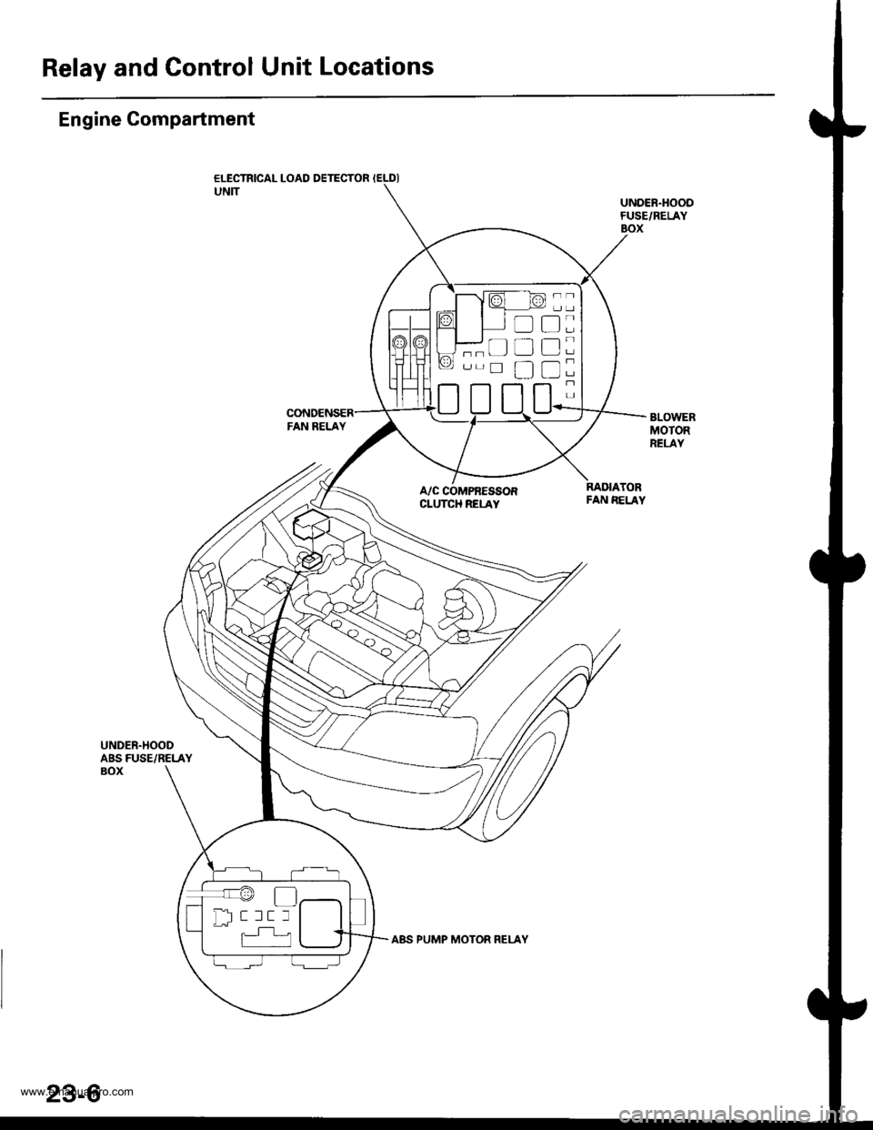
ELECTRICAL LOAD DETECTOR IELDIUNITUNDER.HOODFUSE/RELAYBOX
BLOWERMOTORRELAY
A/C COMPRESSORCLUTCH RELAY
RADIATORFAN EELAY
UNDER.HOODABS FUSE/RELAYBOX
t:
tr
tr
tr
;
-
''r@
Dl-- r rr r
23-6
www.emanualpro.com
Page 1176 of 1395
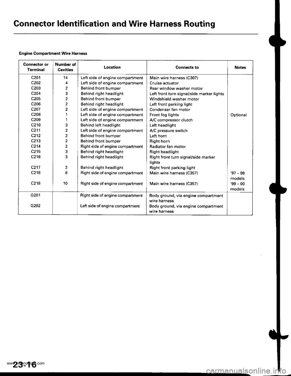
Gonnector ldentification and Wire Harness Routing
Engine Compartment Wire Harness
Connector ol
Terminal
Number of
CavitiesLocationConnects toNotes
c20'l
c202
c203
c204
c205
c206
c207
c208
c209
c210
c212
c213
c2't4
c215
c216
c217
c21A
c218
14
2
2
1'l
2
10
Left side of engine compartment
Left side of engine compartment
Behind front bumper
Behind right headlight
Behind front bumper
Behind right headlight
Left side of engine compartment
Left side of engine compartment
Left side of engine compartment
Behind left headlight
Left side of engine compartment
Behind front bumper
Behind front bumper
Right side of engine compartment
Behind right headlight
Behind right headlight
Behind right headlight
Right side of engine compartment
Right side of engine compadment
Main wire harness (C307)
Cruise actuator
Rear window washer motor
Left front turn signal/side marker lights
Windshield washer motor
Left front parking light
Condenser fan motor
Front fog lights
IVC compressor clutch
Left headlight
IVC pressure switch
Left horn
Right horn
Radiator fan motor
Right headlight
Right front turn signal/side marker
lights
Right front parking light
Main wire harness 1C357)
Main wire harness (C357)
Optional
'97 - 98
models'99 - 00
mooets
G201
G202
Right side of engine companment
Left side of engine compartment
Body ground, via engine compartment
wire harness
Body ground, via engine compartment
wire harness
23-16
www.emanualpro.com
Page 1180 of 1395

Connector ldentification and Wire Harness Routing
Main Wire Harn€ss (left side of dash and floor branchesl {cont,dl
c401
c402
c403
c404
c404
c405
c406
c407
c408
c409
c410
c410
c411
c412
c413
c413
c414
c415
c416
c416
c417
c418
c419
c420
c420
c421
c422
c423
c424
c425
c42A
c426
c437
c438
c438
c439
c440
c441c442
5
20
20
24
't4
8
5
3
12
10'1
18
20'18
10
15
1
4
8
5
5
22
Behind left kick panel
Behind left kick panel
Behind left kick panel
Behind left kick panel
Behind left kick panel
Under left side of dashUnder left side of dashUnder left side of dashUnder left side of dashUnder left side of dashUnder left side of dashUnder left side of dash
Under left side of dashUnder left side of dashUnder left side of dash
Under left side of dash
Under left side of dashUnder left side of dashUnder left side of dashUnder left side of dashUnder left side of dashUnder left side of dashUnder left side of dashUnder left side of dash
Under left side of dashUnder left side of dashUnder left side of dashUnder middle of dashUnder middle of dashUnder middle of dashUnder middle of dashUnder middle of dash
Under left side of dashUnder left side of dash
Under left side of dashUnder left side of dashUnder left side of dashUnder left side of dashUnder left side of dash
Under left side of dash
Under left side of dashUnder left side of dashUnder left side of dashUnder left side of dash
Starter cut relay
Horn relay
Left side wire harness (C558)
Left side wire harness (C559)
Left side wire harness (C559)
Cruise control unitDaytime running lights control unitDaytime running lights control unitlgnition key light control unitInterior wire harness {C701)Cable reel
Cable reel
lgnition key switchlgnition key switch
Combination switch sub-harness {C753)
Combination switch sub-harness (C753)
SRS main harness (C803)
Dashboard wire harness (C503)
Dashboard wire harness (C501)
Dashboard wire harness {C501)Under-dash fuse/relay box (C922)
Under-dash fuse/relay box (C920)
Under-dash fuse/relay box (C919)
lntegrated control unit
Integrated control unitFront fog lights switchBrake switch
Interlock control unitReverse relay
Rear accessory socket relayRear accessory socket relayRear heated oxygen sensor sub-harness (C722)
Security control unitSecurity starter cut relay (for securityalarm system)
Junction connector (for interlock system)Security wire harnessSecurity wire harnessRear window wiper control unitCombination switch sub-harness (C760)
Combination switch sub-harness (C760)
Securlty indicatorSecurity valet switchClutch interlock switchClutch switch (for cruise control)
'97 model'98 - 00mooets
Canada
Canada'97 model
'97 model'98 - 00models
'97 - 98models'99 - 00
moqets
'97 model'98 - 00mooets
Optional
Optional
Optional
Optional
Optional'97 model
'97 - 98mooels'99 - 00models
OptionalOptional
Mfi
Mlr
Under left side of dashBody ground, via main wire harness
23-20
www.emanualpro.com
Page 1203 of 1395

Power Distribution
Fuse-to-Gomponent(sl Index (numerical sequence)
Under-hood Fuse/Rolay Box:
41
43
44
46
47
48
49
50
52
Capacity
'100 A
40A
7.5 A
15 A
40A
7.5 A
30A
204
204
15 A
10A
40A
40A
204
20A
Capacity
40A
204
7.5 A
wiro ColorFuseCircuit(s) Prot€cted
A
lgnition switch (BAT)
lntegrated control unit
Ceiling lights
Spotlights
PGM-Fl main relay
Not used
No. 7, 8, 10, 11 fuse in the under-dash fuse/relay box
Audio unit
Clock {'98 - 00 models)
Data link connector ('98 - 00 models)
ECM (VBU) {'98 - 00 models: M/T)
Heater control panel
PCM (VBU) (A./T)
Combination light switch (via under-dash fuse/relay box)
No. 20, 33 fuse in the under-dash fuss/relay box
Not used
Rear window defogger (via relay)
Door lock control unit
Hatch glass opener solenoid
Keyless door lock control unit ('98 - 00 models)
Horn relay
Horns (via relay)
via brake switch:
ABS control unit
Brake lights
Cruise control unit
ECM ('98 - 00 models: M/T)
High mount brake iight
PCM (4./T)
Trailer lighting connector
Turn signal/hazard relay (via switch)
Option connector (+B)
No. 6 fuse in the under-dash fuse/relay box
Blower motor (via relay)
Condenser fan motor (via relay)
Ay'C compressor clutch (via relay)
Radiator fan motor (via relay)
Wire Color Circuitls) Protoct
53
54
50
WHT/BLK
WHT/RED
WHT/BLK
WHT/BLU
WHT/BLU
WHT
WHT/GRN
WHT/GRN
WHT/GRN
WHT/BLK
WHT/RED
BLU/WHT
WHT
RED
BLK/RED
Under-hood ABS Fuss/nehy Box:
Fusg
61WHT
WHT/GRN
BRN/YEL
ABS pump motor {via relay}
ABS control unit
ABS control unit
{cont'd)
23-43
www.emanualpro.com
Page 1204 of 1395

Power Distribution
Fuse
1
3
5
6
7
I
9
10
11
12
13
14
"^
RED/B LU
RED/GRN
WHT/BLK
RED/VVHT
YEUBLK
RED
GRN/BLK
BLU/BLK
YEVBLK
YEUGRN
RED
BLK/YE L
BLK/VVHT
17
7.5 A
7.5 A
BLVBLU
BLKA/EL
18
19
20
22
7.54
7.54
l0 A
10 A
YEUBLK
YEVRED
BLKAr'YHT
RED /VHT
RED/YE L
Fuse-to-Component(sl Index (numerical sequencel (cont'dl
Under-dash Fuse/Relay Box:
Capacity
10 A
10 A
10 A
10 A
20A
204
15A
204
204
7.5 A'15 A
7.5 A
7.5 A
Wire ColorCircuit{s) Protected
Not used
Not used
Rear window washer motor (via switch)
Rear window wiper control unit ('97 model)
Rear window wiper motor
Daytime running rights resister {Canada)
Right headlight {High beam}
Daytime running rights resister (Canada)
High beam indjcator light
Left headlight (High beam)
Rear accessory socket (via relay)
Left rear power window motor (via switch)
Right rear power window motor (via switch)
Distributor (ignition control module)
Front passenger's power window motor (via switch)
Driver's power window motor {via switch)
Power window master switch (power window control unit)
Turn signal/hazard relay (via switch)
PGM-FI main relay
SRS unit (VA)
Cruise control unit (via switch)
Cruise main switch indicator light
Alternator
Charging system light
ELD unit (USA)
EVAP bypass solenoid valve ('98 - 00 models)
EVAP control canister vent shut valve ('98 - 00 models)
EVAP purge control solenoid valve
Primary HO2S
Secondary H02S
VSS
ABS control unit
Option connector (lG2)
Ay'C compressor clutch relay
Blower motor high relay
Blower motor relay
Condenser fan relay
Heater control panel
Left power mirror actuators (via switch)
Mode control motor
Radiator fan relay
Recirculation control motor
Right power mirror actuators (via switch)
Daytime running lights control unit (Canada)
Back-up lights
Reverse relay (A"/T)
Daytime running lights control unit (Canada)
Right headlight (Low beam)
Left headlight (Low beam)
23-44
www.emanualpro.com
Page 1207 of 1395

BLKG401
GroundWir€ ColorComponent or Circuits Grounded
ABS indicator circuit
ABS control unit
Ashtray light
A/T gear position indicator dimming circuit
Brake fluid level switch
Clock ('98 - 00 models)
Clutch inrerlock switch (M/T)
Clutch switch (Mff)
Cruise main switch
Cruise indicator circuit
Cruise control unit
Dash lights brightness controller
Data iink connector
Daytime running rights control unit (Canada)
Front accessary socket
Gauge and indicators
Heater control panel
lgnition key light control unit ('97 model)
lgnition key switch
Integrated control unit
Interlock control unit (Ay'T)
Parking pin switch {A,/T)
Power window relay
Rear accessary socket relay
Bear window defogger relay
Rear window wiper control unit ('97 model)
Service check connector
Spotlights
SRS indicator circuit
Turn signal/hazard relay
Windshield wiper motor
Windshield wiper/washer switch- plus everything grounded through G402
ABS control unit
Blower motor relay
Blower motor high relay
ELD unit (USA)
Power transistor- plus everything grounded through G401
BLKG402
{cont'd)
23-47
www.emanualpro.com
Page 1213 of 1395
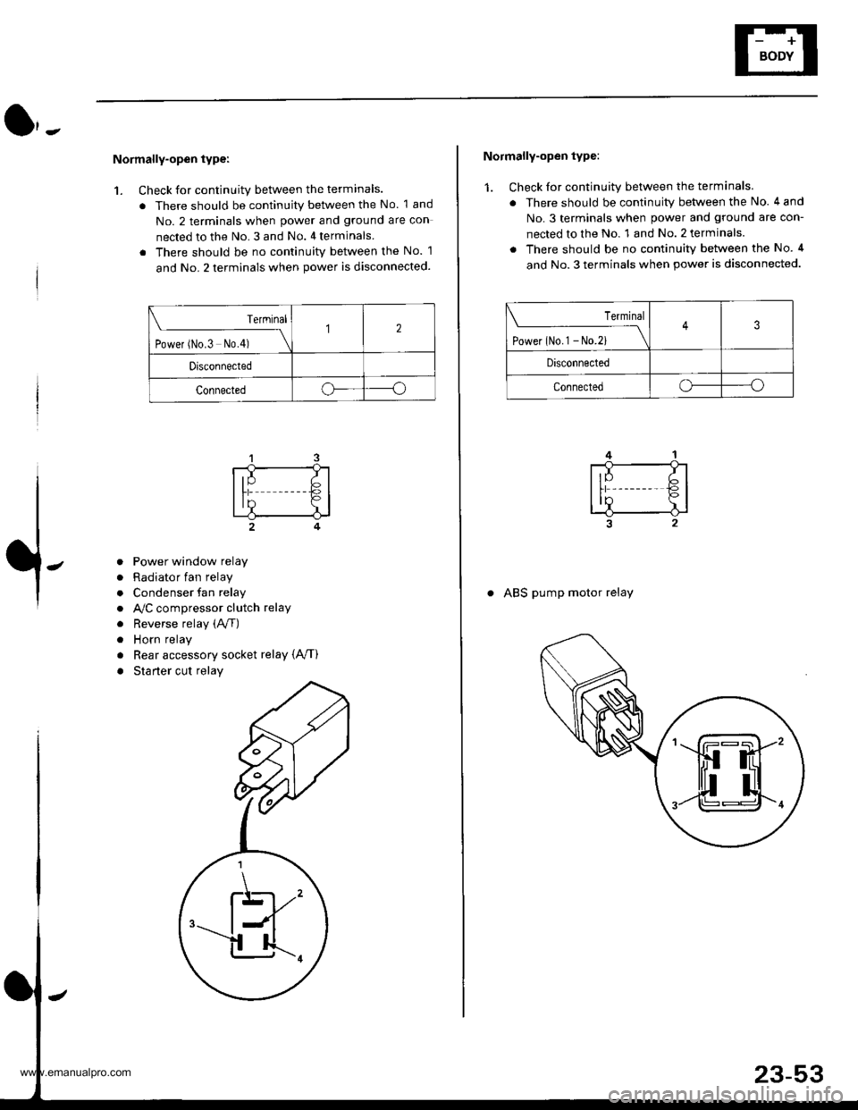
Normally-open type:
1. Check for continuity between the terminals.
. There should be continuity between the No. 1 and
No. 2 terminals when power and ground are con
nected to the No. 3 and No. 4 terminals
. There should be no continuitv between the No. 1
and No. 2 terminals when power is disconnected.
Terminal
t.*", ^"- t*f \
12
Drsconnected
Connectedoo
a
a
a
a
a
a
Power window relay
Radiator fan relay
Condenser fan relay
A,/C compressor clutch relay
Reverse relay (A/f)
Horn relay
Rear accessory socket relay {A,/T)
Starter cut relay
\K,
Normally-open type:
1. Check for continuity between the terminals.
. There should be continuity between the No. 4 and
No.3 terminals when power and ground are con-
nected to the No. 1 and No. 2 terminals.
. There should be no continuity between the No. 4
and No. 3 terminals when power is disconnected.
Terminal
tl**^-*
-_\3
Disconnected
Connectedo----o
. ABS pump motor relay
www.emanualpro.com