spring HONDA CR-V 1998 RD1-RD3 / 1.G User Guide
[x] Cancel search | Manufacturer: HONDA, Model Year: 1998, Model line: CR-V, Model: HONDA CR-V 1998 RD1-RD3 / 1.GPages: 1395, PDF Size: 35.62 MB
Page 115 of 1395
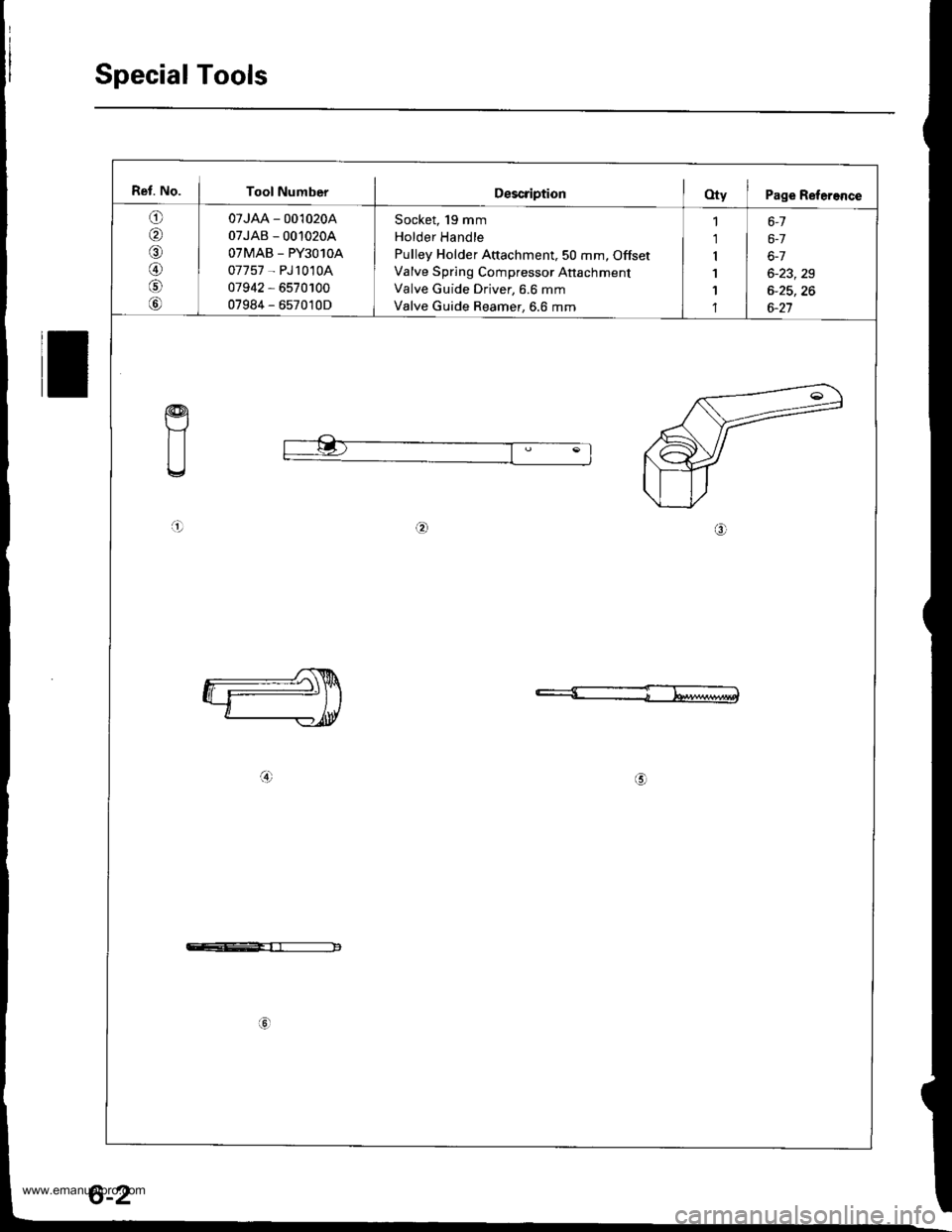
Special Tools
Ref. No. I Tool NumberDescription(Xy I Page Refereflce
o
,61
A)
07JAA - 001020A
07JAB - 00'10204
OTMAB _ PY3O1OA
07757 - PJ1010A
07942 - 6570100
07984 - 657010D
Socket, 19 mm
Holder Handle
Pulley Holder Attachment,50 mm, Offset
Valve Spring Compressor Anachment
Valve Guide Driver, 6.6 mm
Valve Guide Reamer, 6.6 mm
1 6-1
1 | 6-7
r I 6-7
1 6-23,29
1 I 6-25,26'l | 6-27
a!)
a!)
c--E-rr------------
6-2
www.emanualpro.com
Page 118 of 1395
Valve Seals
Replacement (cylinder head removal not required)
The procedure shown below applies when using the in-
car valve spring compressor (Snap-on YA8845 with
YA8845-2A 7/8" auachment). Use approved eye protec-
tion.
1. Turn the crankshaft so that the No. 1 and the No. 4
pistons are at top dead center (TDC).
2. Remove the cylinder head cover.
3. Remove the distributor.
4. Loosen and disconnect the timing belt from the
camshaft pulleys.
5. Remove the camshaft holder bolts. then remove the
camshaft holders, the camshafts and rocker arms.
lntake Valve Seals
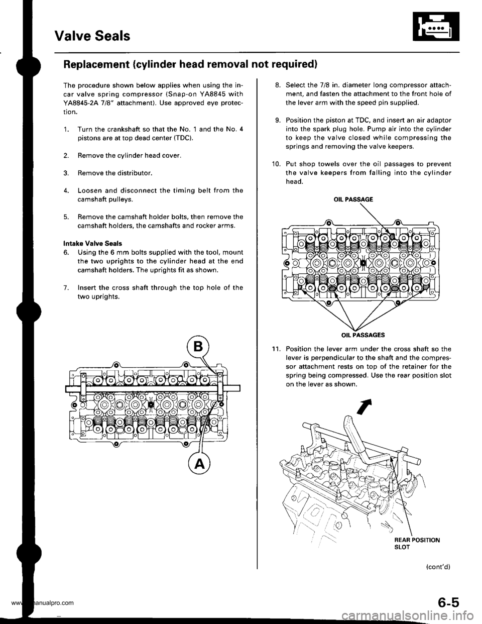
6. Using the 6 mm bolts supplied with the tool, mount
the two uprights to the cylinder head at the end
camshaft holders. The uprights fit as shown.
7. Insert the cross shaft through the top hole of the
two uprights,
at.
9.
Select the 7/8 in. diameter long compressor attach-
ment, and fasten the attachment to the front hole of
the lever arm with the speed pin supplied.
Position the piston at TDC, and insen an air adaptor
into the spark plug hole. Pump air into the cylinder
to keep the valve closed while compressing the
springs and removing the valve keepers.
10. Put shop towels over the oil passages to prevent
the valve keepers from falling into the cylinder
head.
Position the lever arm under the cross shaft so the
lever is perpendicular to the shaft and the compres-
sor attachment rests on top of the retainer for the
spring being compressed. Use the rear position slot
on the lever as shown,
't1.
OIL PASSAGE
OIL PASSAGES
(cont'd)
6-5
www.emanualpro.com
Page 119 of 1395
Valve Seals
12.
Replacement (cylinder head removal not requiredl (cont'dl
Using an upward motion on the lever arm, compress
the valve spring and remove the keepers from the
valve stem. Slowly release pressure on the spring.
Repeat step 11 for the other valve in that cylinder.
Remove the valve seals (see page 6-24).
Installthe valve seals (see page 6-29).
lnstall the springs, the retainers and the keepers in
reverse order of removal.
'17. Repeat steps 9 to 16 for the other three cylinders.
Exhaust valve Seals
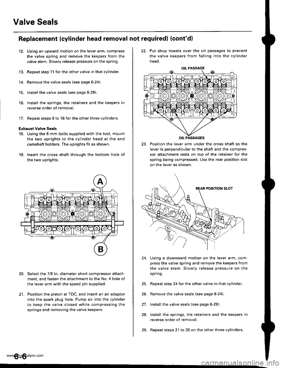
18. Using the 5 mm bolts supplied with the tool, mount
the two uprights to the cylinder head at the end
camshaft holders. The uprights fit as shown.
19. Insert the cross shaft through the bottom hole of
the two uprights.
Select the 7/8 in. diameter short compressor attach
ment, and fasten the attachment to the No. 4 hole of
the lever arm with the speed pin supplied.
Position the piston at TDC, and insert an air adaptor
into the spark plug hole. Pump air into the cylinder
to keep the valve closed while compressing the
springs and removing the valve keepers.
13.
14.
15.
16.
20.
t1
22. Put shop towels over the oil passages to prevent
the valve keepers from falling into the cylinder
neao.
23. Position the lever arm under the cross shaft so the
lever is perpendicular to the shaft and the compres-
sor attachment rests on top of the retainer for the
spring being compressed. Use the rear position slot
on the lever as shown.
Using a downward motion on the lever arm, com-
press the valve spring and remove the keepers from
the valve stem. Slowly release pressure on the
spring.
Repeat step 24 for the other valve in that cylinder.
Remove the valve seals (see page 6-24).
Install the valve seals (see page 6-29).
Install the springs, the retainers and the keepers in
reverse order of removal.
Repeat steps 21 to 28 on the other three cylinders.
24.
21.
28.
29.
o-o
www.emanualpro.com
Page 128 of 1395
-?E
handling a metal gasket. take care not to fold it or damage the contact surface.
Prior to reassembling, clean all the parts in solvent, dry them and apply lubricant to any contact parts.
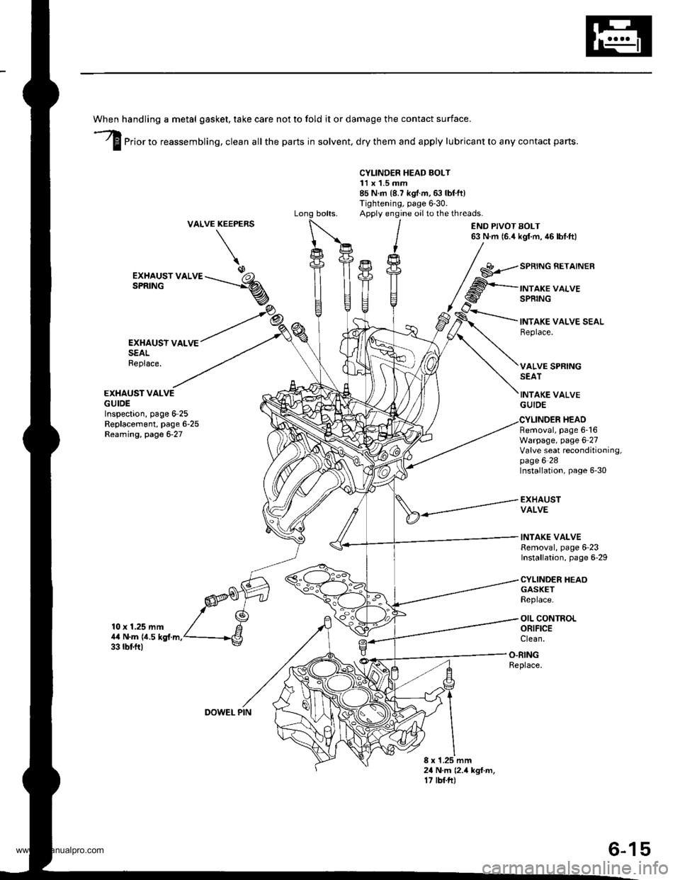
CYLINDER HEAD BOLT11 x 1.5 mm85 N.m {8.7 kgf.m,6:} lbf.ft)Tightening, page 6'30.Apply engine oilto the threads.VALVEKEEPERS
\
END PIVOT BOLT63 N.m 16.4 kgl m, 46 lbf.ft)
EXHAUSY VALVESEALReplace.
EXHAUST VALVEGUIDEInspection, page 6-25Replacem6nt, page 6-25Reaming, page 6-27
10 x 1.25 mm4,0 N.m {i1.5 kgf.m.33 rbf.ft)
GASKETReplace.
OIL CONTROLORIFICEClean.
EXHAUST VALVESPRING
SPRING BETAINER
INTAKE VALVESPRING
INTAKE VALVE SEALReplace.
VALVE SPRINGSEAT
INTAKE VALVEGUIDE
Removal, page 6-16Warpage, page 6 27Valve seat reconditioning,page 6 28Installation, page 6-30
EXHAUSTVALVE
INTAKE VALVERemoval, page 6-23Installation, page 6-29
CYLINDER HEAO
HEAD
O.RINGReplace.
8 x 1.25 mm24 N.m (2.4 kgf.m,17 tbf.ft)
DOWEL PIN
6-15
www.emanualpro.com
Page 136 of 1395
Valves, Valve Springs
and Valve Seals
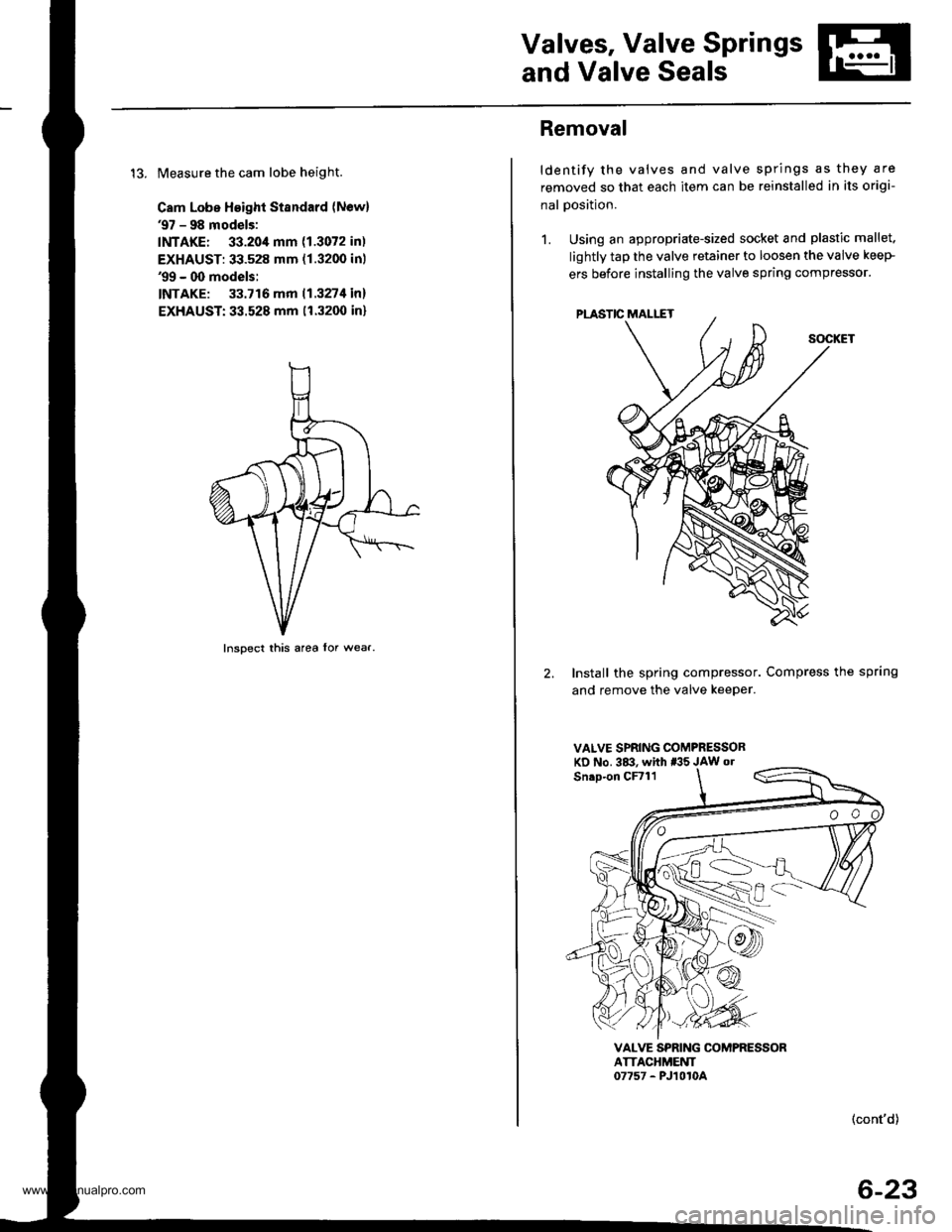
13. Measure the cam lobe height.
Cam Lobe Height Standard (Newl'97 - 98 models:
INTAKE: 33.20,1mm (1.3072 in)
EXHAUST: 33.528 mm (1.3200 inl'99 - 00 models:
INTAKE: 33.716 mm 11.327t1in)
EXHAUST:33.528 mm (1.3200 in)
Inspect this area lor wear.
Removal
ldentify the valves and valve springs as they are
removed so that each item can be reinstalled in its origi-
nal Dosition.
1. Using an appropriate-sized socket and plastic mallet.
lightly tap the valve retainer to loosen the valve keeP
ers before installing the valve spring compressor'
2. Install the spring compressor. Compress the spring
and remove the valve keeper.
VALVE SPRING COMPRESSORKD No. 3&!. whh *'5 JAW o.
VALVE SPRING COMPRESSORATTACHMEUT07757 - PJ1010A
(cont'd)
6-23
www.emanualpro.com
Page 137 of 1395
Valves, Valve Springs and Valve Seals
Removal (cont'dl
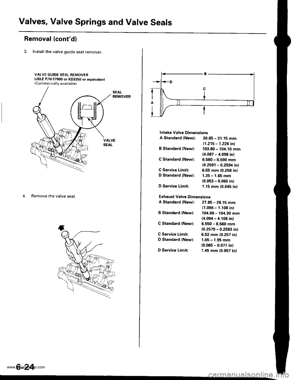
3. Install the valve guide seal remover.
VALVE GUIDE SEAL REMOVERLISLE P/N 57900 or KD3350 or equivalent(Commerciallv available)
4. Remove the valve seal.
6-24
Intake Valve Dimensions
A Standard {New}: 30.85 - 31.15 mm
B Standard (New):
G Standard {Newl:
C Service Limiti
D Standard lNewl:
D Service Limit:
B Standard (Newl:
C Standard {New):
C Service Limit:
D Standard lNewl:
D Service Limit:
11.21s - 1.226 inl
103.80 - 10/t.10 mm
{i[.087 - 4.098 in)
6.580 - 6.590 mm(0.2591 - 0.2594 in)
6.55 mm (0.258 inl
1.35 - 1.65 mm(0.053 - 0.05s in)
1.15 mm (0.045 in)
11.096 - 1.108 in)
10,1.00 - 10,1.30 mm(il.09i[ - it.l06 in)
6.550 - 6.560 mm
10.2579 - 0.2583 inl
6.52 mm (0.257 inl
1.65 - 1.95 mm
10.065 - 0.077 in)
1.45 mm (0.057 inl
Exhausi Valv€ Dimensions
A Standard (Newl: 27.85 - 28.15 mm
www.emanualpro.com
Page 142 of 1395
Valves, Valve Springs and Valve Seals
lnstallation
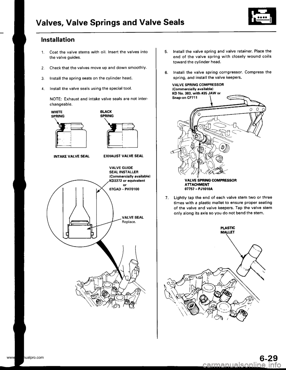
Coat the valve stems with oil. Insert the valves into
the valve guides.
Check that the valves move up and down smoothly.
Install the spring seats on the cylinder head.
Install the valve seals using the special tool.
NOTE: Exhaust and intake valve seals are not inter-
1.
changeable.
WHITESPRING
BLACKSPRING
INTAKE VALVE SEALEXHAUST VALVE SEAL
VALVE GUIDESEAL INSTALLER
lCommercially available)KO3372 or equival€ntot07GAD - PH70100
VALVE SPRING COMPRESSOR
lComm6rcially available)KD No. 383, with *35 JAw or
7.
Install the valve spring and valve retainer. Place the
end of the valve spring with closely wound coils
toward the cylinder head,
Install the valve spring compressor. Compress the
spring, and install the valve keepers.
VALVE SPRIT{G OOMPfi ESSORATTACHMENT0775' - PJ1010A
Lightly tap the end of each valve stem two or three
times with a plastic mallet to ensure proper seating
of the valve and valve keepers, Tap the valve stem
only along its axis so you do not bend the stem.
PLASTE
6-29
www.emanualpro.com
Page 144 of 1395
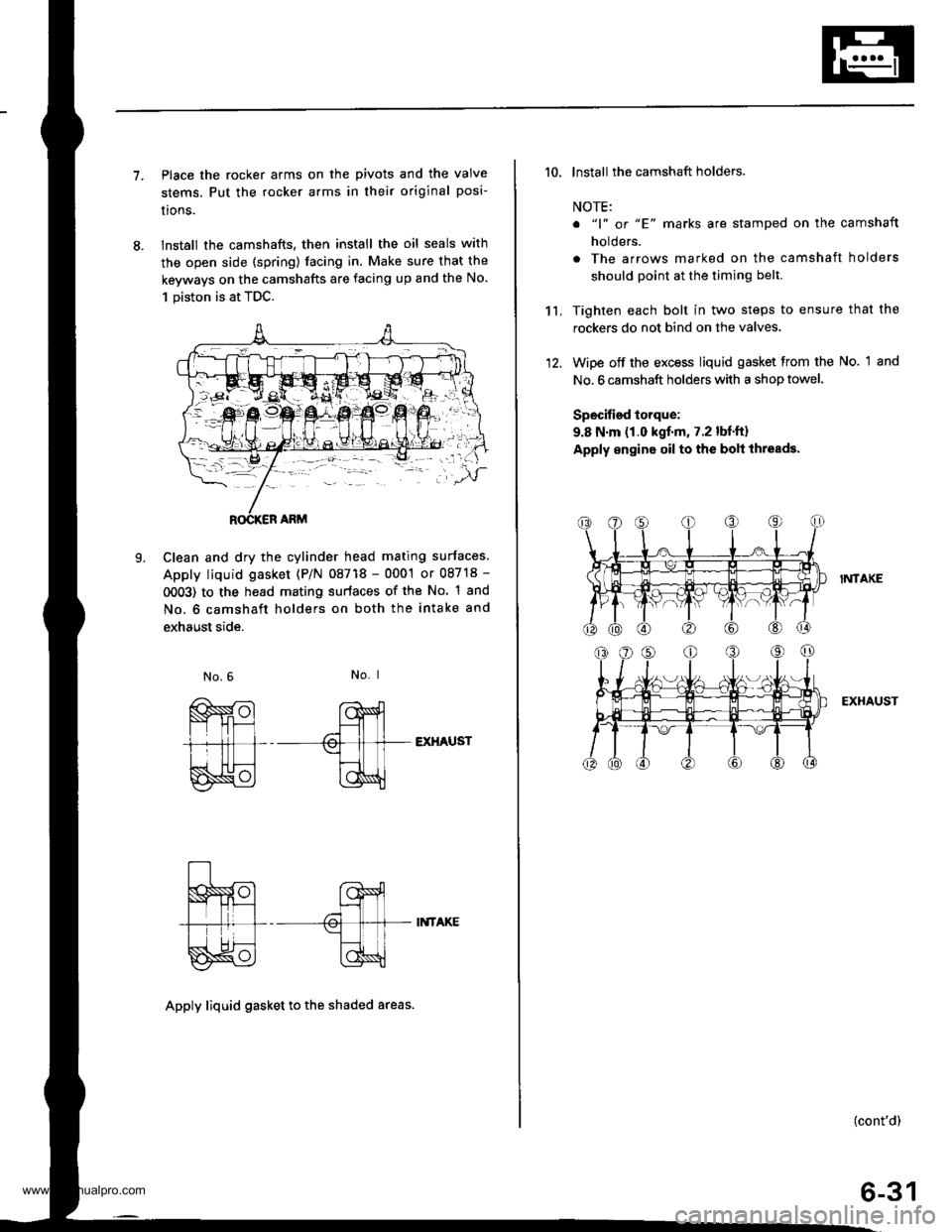
7.Place the rocker arms on the pivots and the valve
stems. Put the rocker arms in their original posi-
lrons.
lnstall the camshafts, then install the oil seals with
the open side (spring) facing in. Make sure that the
keyways on the camshafts are facing up and the No.
1 piston is at TDC.
Clean and dry the cylinder head mating surfaces.
Apply liquid gasket (P/N 08718 - 0001 or 08718 -
0OO3) to the head mating surfaces of the No. 1 and
No. 6 camshaft holders on both the intake and
exhaust side.
L
No. I
EXHAUST
II{TAKE
Apply liquid gasket to th€ shaded areas.
't't,
'10. lnstall the camshaft holders.
NOTE:
o "1" or "E' marks are stamped on the camshaft
holders.
. The arrows marked on the camshaft holders
should point at the timing belt.
Tighten each bolt in two steps to ensure that the
rockers do not bind on the valves.
Wipe off the excess liquid gasket from the No. 1 and
No. 6 camshaft holders with a shop towel,
Specified torque:
9.8 N.m (1.0 kgf.m, 7.2 lbf.ft)
Apply engine oil to the bolt ihreads.
I?,ITAKE
EXHAUST
(cont'd)
6-31
www.emanualpro.com
Page 148 of 1395
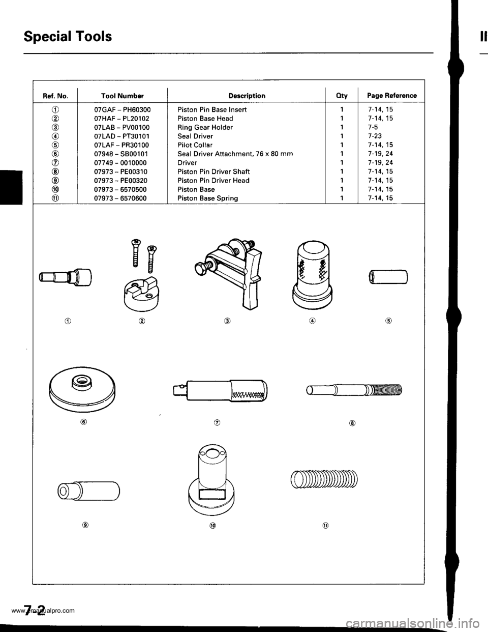
Special Toolstl
Ref, No. I Tool NumborDescriptionOty Page Reterence
o
@
@/6
@
o
@
@
@
@
07GAF - PH60300
07HAF - P120102
07LAB - PV00100
07LAD - PT30101
07LAF - PR30100
07948 - S800101
07749 - 0010000
07973 - PE00310
07973 - PE00320
07973 - 6570500
07973 - 6570600
Piston Pin Base lnsert
Piston Base Head
Ring Gear Holder
Seal Driver
Pilot Collar
Seal Driver Attachment. 76 x 80 mm
Driver
Piston Pin Driver Shaft
Piston Pin Driver Head
Piston Base
Piston Base Spring
,l
1
I
I
1
1
1
1
1
1
1
7-14,15
1-'t4,15
1-5
1-23
7-14,15
7-'t9,24
7 -'t9, 24
1-14,15
7-14,15
7-'t4,15
7-14,15
eEEg
o
a@
0
o@
7-2
www.emanualpro.com
Page 403 of 1395
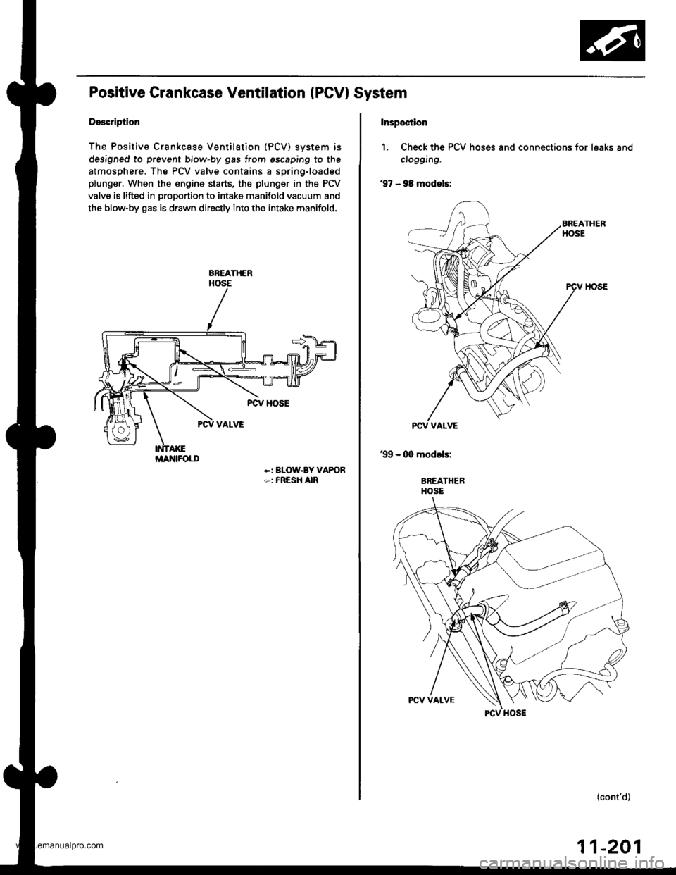
Positive Grankcase Ventilation (PGVI System
Description
The Positive Crankcase Ventilation (PCV) svstem is
designed to prevent blow-by gas from escaping to the
atmosphere. The PCV valve contains a spring-loaded
plunger, When the engine starts, the plunger in the PCV
valve is lifted in proportion to intake manitold vacuum and
the blow-by gas is drawn directly into the intake manifold.
-: BLOW.BY VAPOR-: FRESH AIR
i/lAlrllFOLD
Inspoction
1. Check the PCV hoses and connections for leaks and
clogging.
'97 - 98 models:
'99 - (X) models:
BREATHERHOSE
(cont'd)
11-201
www.emanualpro.com