Lock HONDA CR-V 1998 RD1-RD3 / 1.G Workshop Manual
[x] Cancel search | Manufacturer: HONDA, Model Year: 1998, Model line: CR-V, Model: HONDA CR-V 1998 RD1-RD3 / 1.GPages: 1395, PDF Size: 35.62 MB
Page 917 of 1395
Rear Suspension
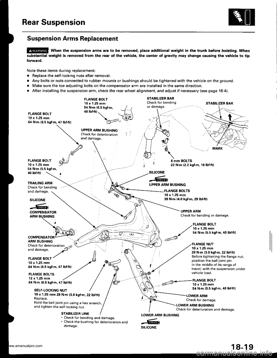
Suspension Arms Replacement
@ when the suspension arms are to be removed, plsce additional weight in lhe trunk beto.o hoisting. when
substantial weight is removed from the rear of the vehicle, the center ot grsvity m8y chango causing the vehicle to tip
forward.
Note these items during replacement:
. Replace the self-locking nuts after removal.
. Any bolts or nuts connected to rubber mounts or bushings should be tightened with the vehicle on the ground.
. Make sure the toe adjusting bolts on the compensator arm are installed in the same direction,
. After installing the suspension arm, check the rear wheel alig nment, and adjust if necessa ry (see page 18-4),
STABILIZER BARCheck for bendingor oamage.
FLANGE EOLT10 x 1.25 mm64 N.m 16.5 kgf.m,47 lbf.ft)
FLANGE BOLT10 x 1.25 mm54 N.m (5.5 kgt.m, / t40 lbf.ftt. --1 \ \A1(\
\a'v..:r
UPPER ARM BUSHINGCheck for deteriorationand damage.
il ,
FLANGE BOLT'l0 r 1.25 mm54 N.m (5.5 kgf.m,
8 mm EOLTS22 N.m {2.2 kgf.m, 16 bl.ftl
40 rbtft)
'ano oamage.
TRAILING ARMCheck for bending
stLtcoNE
-6lUPPER ARM
COMPENSATORARM BUSHING
64 N.m 16.5 kgf.m, 47 lbtftl
SELF.LOCKING NUT
BUSHING
FLANGE BOLT10 x 1.25 mm54 N.m {5.5 kgf.m, 40 lbf.ft}
FLANGE BOLTS10 x 1.25 mm39 N.m 14.0 kgf.m, 29 lbf.ft)stLtcoNE
.@iCOMPENSATORARM BUSHING
UPPER ARMCheck lor bending or damage.
FLANGE NUT10 x 1 .25 mm29 N.m {3.0 kg{.fl,22 lbf.ft}Before tightening the flange nut,position the balljoint pinin the middle of its range oftravel, with the suspension undervehicle load.
10 x 1.25 mm 29 N.m (3.0 kgl.m, 22 tbf.ft)Replace.Hold the ball ioint pin using a hex wrenct,,and tighten the self-locking nut.
STABILIZER LINK
Check tor damage.
LOWER ARM BUSHINGCheck for deterioration and damage.
. Check for bending and damage.. Check the bushing tor deterioration anddamage.
LOWEN ARM
-6ilstLrcoNE
STABILIZER 8AR
,/ FLANGE BOLT
// 10 x 1.25 mm
^/ s4 N.m 15.5 kst'm, 40 lbf ftl
BUSHING
www.emanualpro.com
Page 918 of 1395
Rear Suspension
Hub Bearing Unit Replacement
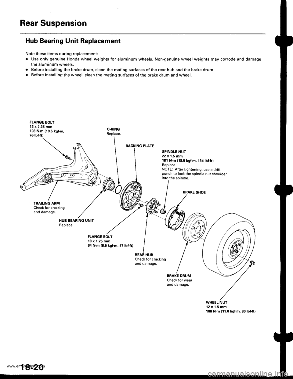
Note these items during replacement:
. Use only genuine Honda wheel weights for aluminum wheels. Non-genuine wheel weights may corrode and damage
the aluminum wheels.
. Before installing the brake drum, clean the mating surfaces of the rear hub and the brake drum.
. Before installing the wheel, clean the mating surfaces of the brake drum and wheel.
FLANGE BOLI12 x 1,25 mm103 N.m 110.5 kgf.m,76 tbtfr)
BACKING PLATE
SPINDI-E NUT22 x'1.5 mm181 N.m {18.5 kgf.m, 134 lbf.ftlReplace.NOTE: Alter tightening, use a driftpunch to lock the spindle nut shoulderinto the spindle.
BRAKE SHOE
TRAILING ARMCheck {or crackingano oamage.
FLANGE BOLT10 x 1.25 mm64 N'm 16.5 kgf.m, 4? lbt.ft)
Check for crackingano oamage.
BRAKE DRUMCheck for wearano oamage,
WHEEL NUT12 x 1.5 mm108 N.m {11.0 kgt m,80lbtftl
1A-20
www.emanualpro.com
Page 919 of 1395
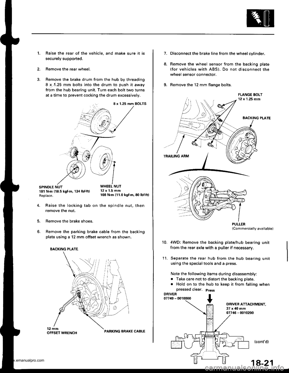
Raise the rear of the vehicle, and make sure it is
securely supponed.
Remove the rear wheel.
Remove the brake drum from the hub by threading
8 x,r.25 mm bolts into the drum to push it away
from the hub bearing unit. Turn each bolt two turns
at a time to prevent cocking the drum excessively.
SPINDLE NUTWHEEL NUT
r81 N.m t18.5 kgt m, 134 lbt'ftl 12 x 1.5 mm
Replace. 108 N m 111.0 kgf'm, 80 lbf ftl
't.
4.
8 x 1.25 mm BOLTS
i+/3 /',1
"@,1 /
.'--7 J-->-
5.
6.
Raise the locking tab on the spindle nut, then
remove the nut.
Remove the brake shoes.
Remove the parking brake cable from the backing
plate using a 12 mm offset wrench as shown.
BACKING PLATE
PARKING ARAKE CABLE
1a-21
7.
6.
Disconnect the brake line from the wheel cylinder.
Remove the wheel sensor from the backing plate
(for vehicles with ABS). Do not disconnect the
wheel sensor connector.
Remove the 12 mm flange bolts.
PULLERlCommercially available)
4WD; Remove the backing plate/hub bearing unit
from the rear axle with a puller if necessary.
Separate the rear hub from the hub bearing unit
using the specialtools and a press.
Note the following items during disassembly:
. Take care not to distort the backing plate.
. Hold on to the hub to keep it from falling when
a
10.
11.
DRIVER ATTACHMENT,37 x ilo mm07746 - 0010200
(cont'd)
www.emanualpro.com
Page 922 of 1395
Rear Damper
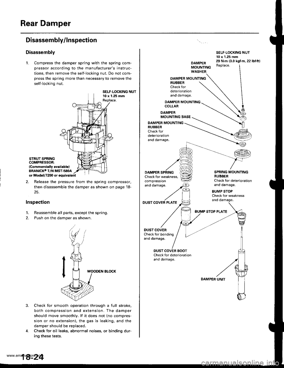
Disassembly/lnspection
Disassembly
L Compress the damper spring with the spring com-
pressor according to the manufacturer's instruc-
tions, then remove the self-locking nut. Do not com-
press the spring more than necessary to remove the
self-locking nut.
SELF-LOCKING NUT10 x 1.25 mmReplace.
STRUT SPRINGCOMPRESSOR:lCommercirlly avaihblo)BRANICKO I/N MSI-580Aor Mod6l/7200 or equivalent
2. Release the pressure from the spring compressor,
then disassemble the damper as shown on page 18-
25.
Inspection
1. Reassemble all parts, except the spring.
2. Push on the damper as shown.
3.
WOODEN ELOCK
Check for smooth operation through a full stroke,
both compression and extension. The damper
should move smoothly. lf it does not (no compres-
sion or no extension), the gas is leaking, and the
damper should be replaced.
Check for oil leaks, abnormal noises, or binding dur-
ino these tests.
4.
SELF-LOCKING NUT10 x 1.25 mm
OAMPERMOUNTINGWASHER
29 N.m {3.0 kgf.m, 22 lbf.ft)Beplace.
OAMPER MOUNTINGRUBBERCheck fordeteriorationano oamage.
DAMPER MOUNTINGCOLLAR
DAMPERMOUNTING BASE
DAMPER MOUNTINGRUBBERCheck fordeteriorationano oamage.
'"dd"^.s"'
//F,
DAMPERCheck for weakness,compressron
DUST COVER PLATE
DUST COVERCheck for bendingand damage.
SPRING MOUNTINGRUBBERCheck Ior deteriorationand damage.
BUMP STOPCheck for weaknessano oamage.
DUST COVEN BOOTCheck for deterioralionano oamage.
BUMP STOP PLATE
DAMPER
www.emanualpro.com
Page 923 of 1395
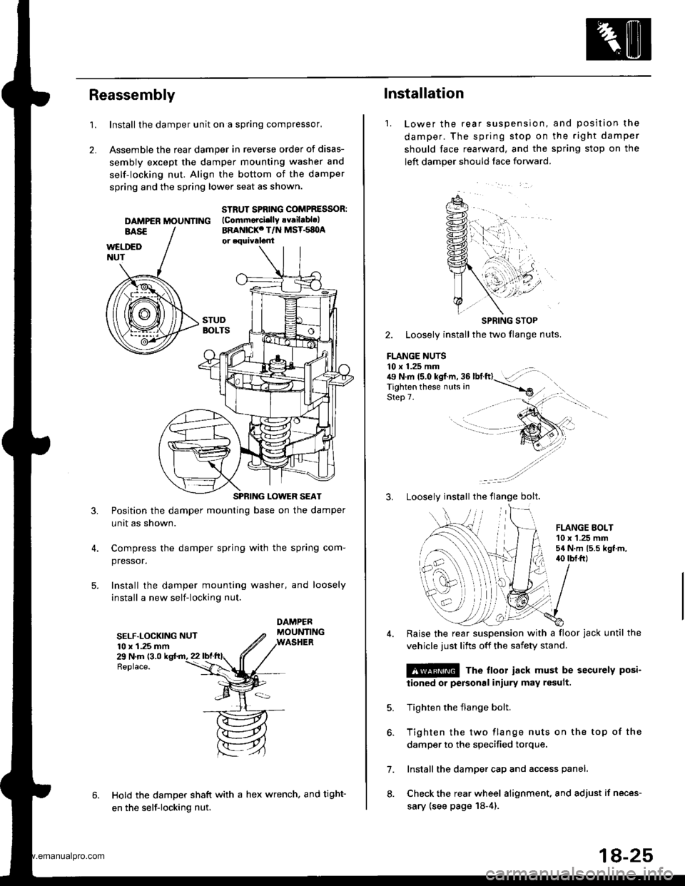
Reassembly
1.Install the damper unit on a spring compressor,
Assemble the rear damper in reverse order of disas-
sembly except the damper mounting washer and
self-locking nut. Align the bottom of the damper
spring and the spring lower seat as shown.
2.
DAMPER MOUNNNG
STRUT SPBING COMPRESSOR:(Commorcislly !v.ilablelBRANICKC T/N MST.s8OA
3.Position the damper mounting base on the damper
unit as shown.
Compress the damper spring with the spring com-
pressor.
Install the damper mounting washer, and loosely
install a new self-locking nut.
SELF.LOCKING NUT10 x 1.25 mm29 N.m (3.0
Replace.
Hold the damper shaft with a hex wrench, and tight-
en the self-locking nut.
1.
lnstallation
Lower the rear suspenston,
damper. The spring stop on
should face rearward, and the
left damper should face forward.
and position the
the right damper
sprang stop on the
SPRING STOP
2. Loosely install the two flange nuts.
FLANGE NUTS10 x 1.25 mm . .:{9 N.m 15.0 kgf.m, 36 lbtft}- :',,-rigf't"n if'"""_nrr. in ----.-*
qla^ 7Step 7.
3. Loosely install the flange bolt.
FLANGE EOLT10 x 1.25 mm54 N.m 15.5 kgt.m,40 tbI.ft)
6.
7.
8.
Raise the rear suspension with a floor jack until the
vehicle just lifts off the safety stand.
@ The floor iack must be securely posi-
iioned or personal iniury may result.
Tighten the flange bolt.
Tighten the two flange nuts on the top of the
damper to the specified torque.
Install the damper cap and access panel.
Check the rear wheel alignment. and adjust if neces-
sary (see page 18-4).
18-25
www.emanualpro.com
Page 924 of 1395
Brakes ........... 19-1
Anti-lock Brake System (ABS) ............. 19-25
www.emanualpro.com
Page 929 of 1395
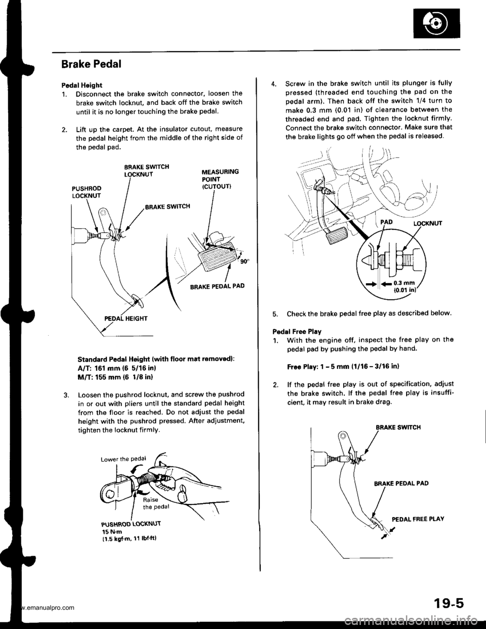
Brake Pedal
Pedal Hoight
1. Disconnect the brake switch connector, loosen the
brake switch locknut, and back off the brake switch
until it is no longer touching the brake pedal.
2. Lift up the carpet, At the insulator cutout, measure
the pedal height from the middle of the right side of
the oedal pad.
BRAKE SWITCH
ERAKE SWITCH
Standard Pedal Height (with floor m8i removed):
A/T: 161 mm (5 5/16 in)
M/T: 155 mm {6 U8 in}
Loosen the pushrod locknut, and screw the pushrod
in or out with pliers until the standard pedal height
from the floor is reached. Do not adjust the pedal
height with the pushrod pressed. After adiustment,
tighten the locknut firmly.
PUSHROD LOCKNUT
15 N.m11.5 kgj m, 11 lbf ftl
4. Screw in the brake switch until its plunger is fully
pressed (threaded end touching the pad on the
pedal arm), Then back otf the switch 1/4 turn to
make 0.3 mm (0.01 in) of clearance between the
threaded end and pad. Tighten the locknut firmly.
Connect the brake switch connecto.. Make sure that
the brake lights 90 off when the pedal is released
5. Checkthe brake pedalfree play as described below
Pedal Free Play
1. With the engine off. inspect the free play on the
pedal pad by pushing the pedal by hand-
Free Play: 1 - 5 mm (1/16 - 3/16 in)
2. lf the pedal free play is out of specification, adiust
the brake switch. lf the pedal free play is insuffi-
cient, it may result in brake drag.
swtTcH
PEOAL PAD
PEDAL FREE PLAY
19-5
www.emanualpro.com
Page 930 of 1395
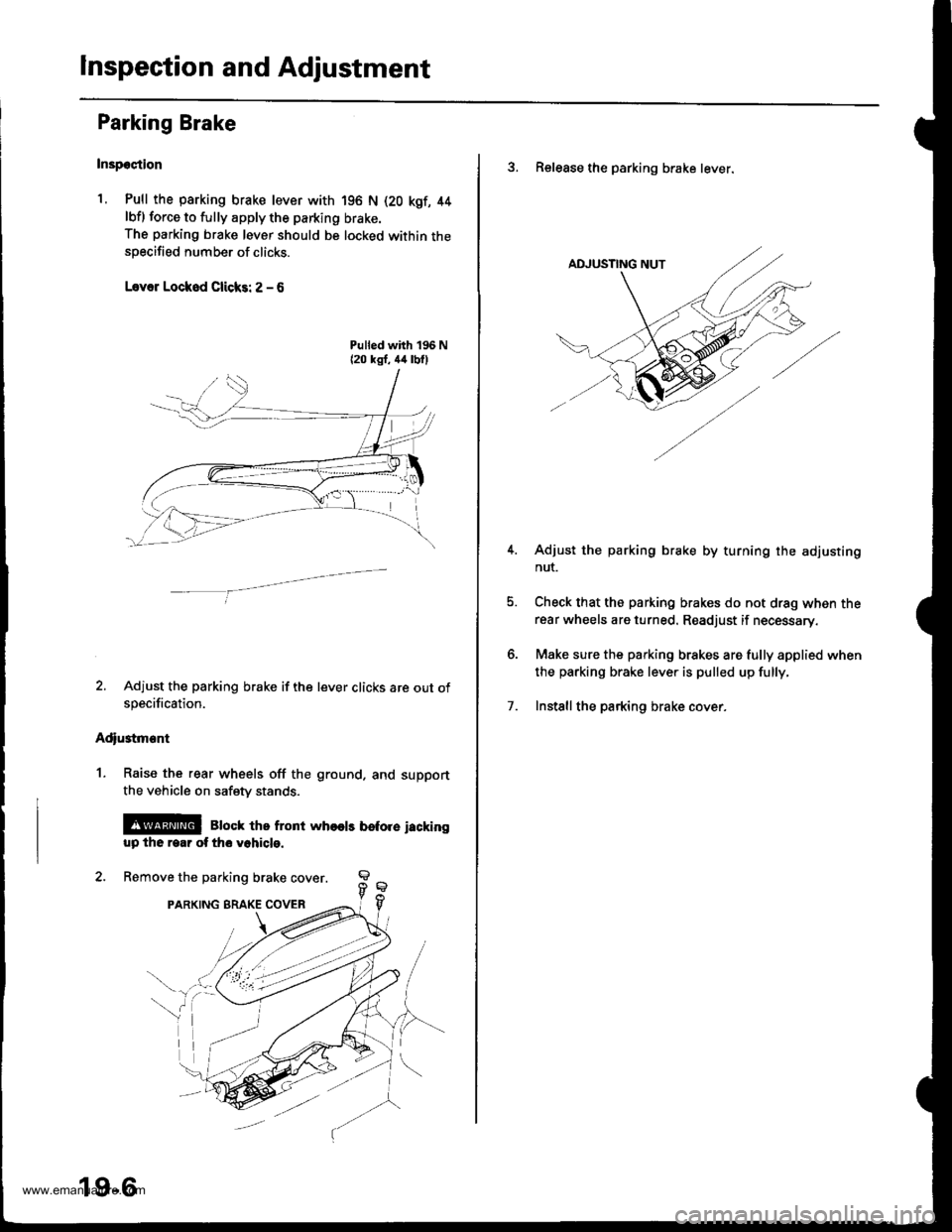
Inspection and Adjustment
Parking Brake
Inspeqtion
1. Pull the parking brake lever with
lbfl force to fully apply the parking
The parking brake lever should be
specified number of clicks.
L.var Lockod Clicks: 2 - 6
196 N (20 kqf, 44
brake.
locked within the
2. Adjust the parking brake if the lever clicks are out ofspecification.
Adiustment
1. Raise the rear wheels off the ground. and support
the vehicle on safety stands.
@@ Bbck tho front who€ts betore iackingup the rear ot tho vohicle.
2. Remove the parking brake cover
PARKING BRAKE COVER
19-6
3. Release the parking brake lever.
Adjust the parking brake by turning the adjusting
nut.
Check that the parking brakes do not drag when therear wheels are turned. Readjust if necessary.
Make sure the parking brakes are fully applied when
the parking brake lever is pulled up fully.
Installthe parking brake cover.7.
www.emanualpro.com
Page 939 of 1395
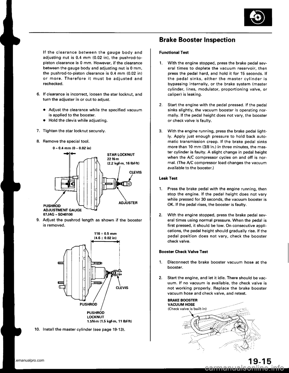
6.
7.
8.
lf the clearance between the gauge body and
adjusting nut is 0.4 mm (0.02 in), the pushrod-to-
piston clearance is 0 mm. However. if the clearance
between the gauge body and adjusting nut is 0 mm,
the pushrod-to-piston clearance is 0.4 mm (0.02 in)
or more. Therefore it must be adjusted and
recheck€d.
lf clearance is incorrect, loosen the star locknut, and
turn the adjuster in or out to adjust.
. Adjust the clearance while the specified vacuum
is applied to the booster.
. Hold the clevis while adjusting.
Tighten the star locknut securely.
Remove the special tool.
0 - 0.4 mm (0 - 0.02 inl
Adjust the pushrod length as shown if the
is removed,
booster
11610.5 mm{4.6 t 0.02 inl
PUSHRODLOCKNUT1.5N.m 11.5 kgf.m. '11 lbtfl)
Install the master cylinder (see page 19-13).
9.
STAR LOCKNUT22 N.m12.2 kgt m. 16 lbtftl
10.
(Check valve is built-in)
Brake Booster Inspection
FunctionalTest
1. With the engine stopped, press the brake pedal sev-
eral times to deplete the vacuum reservoir. thenpress the pedal hard, and hold it for 15 seconds. lf
the pedal sinks, either the master cylinder is
bypassing internally, or the brake system (master
cylinder, lines, modulator, proportioning valve. or
caliper) is leaking.
2. Start the engine with the pedal pressed. lf the pedal
sinks slightly. the vacuum booster is operating nor-
mally. lf the pedal height does not vary, the booster
or check valve is faultv.
3. With the engine running, press the brake pedal light-
ly. Apply just enough pressure to hold back auto-
matic transmission creep. lf the brake pedal sinks
more than 10 mm (3/8 in.) in three minutes, the mas-
ter cylinder is faulty. A slight change in pedal height
when the Ay'C compressor cycles on and off is nor-
mal. (The Ay'C compressor load changes the vacuum
available to the booster.)
Leak Test
1.Press the brake pedal with the engine running, then
stop the engine. lf the pedal height does not vary
while pressed for 30 seconds, the vacuum booster is
OK. lf the pedal rises, the booster is faulty.
With the engine stopped, press the brake pedal sev-
eral times using normal pressure. When the pedal is
first pressed. it should be low, On consecutive appli-
cations, the pedal height should gradually rise. lf thepedal position does not vary. check the booster
check valve.
Boostor Chock Valve Test
1. Disconnect the brake booster vacuum hose at the
booster.
2. Start the engine, and let it idle. There should be vac-
uum. lf no vacuum is available, the check valve is
not working properly. Replace the brake booster
vacuum hose and check valve. and retest.
ERAKE BOOSTERVACUUM HOSE
www.emanualpro.com
Page 940 of 1395
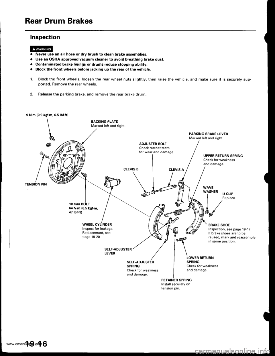
Rear Drum Brakes
Never use an air hose or dry brush to clgan brake assemblies,
Use an OSHA approved vacuum cleaner to avoid breathing brake dust.
Contaminated brake linings or drums reduce stopping ability.
Block the front wheels betore iacking up lhe rear ot the vehicle,
Block the front wheels, loosen the rear wheel nuts slightly, then raise the
poned. Remove the rear wheels.
2. Release the parking brake, and remove the rear brake drum.
I N.m {0.9rbr.ft)kgl.m,5.5
\\
\
196
@
Inspection
a
a
rl
a
1.vehicle, and make sure it is securely sup-
BACKING PLATEMarked left and right.
PARKING EBAKE I-EVERMarked left and right.
ADJUSTER BOLTCheck ratchet teethfor wear and damage.UPPER RETURN SPRINGCheck for weaknessand damage.
CLEVIS BCLEVIS A
64 N.m 16.5 kgl.m,47 lbt.ftl
\L;
SPRINGCheck for weaknessano oamage.
'l-'-' u-cllP
I Replace.
t/
6d/
BRAKE SHOEInspection, see page 19 17lf brake shoes are to bereused, mark and reassemblein same position.
WHEELInspect for leakage.Replacement, seepage 19-20
LOWER RETURNSPRINGCheck for weaknessano oamage.
RETAINER SPRINGInstall securely onlensron prn.
19-16
www.emanualpro.com