25p connector HONDA CR-V 1998 RD1-RD3 / 1.G Owner's Manual
[x] Cancel search | Manufacturer: HONDA, Model Year: 1998, Model line: CR-V, Model: HONDA CR-V 1998 RD1-RD3 / 1.GPages: 1395, PDF Size: 35.62 MB
Page 611 of 1395
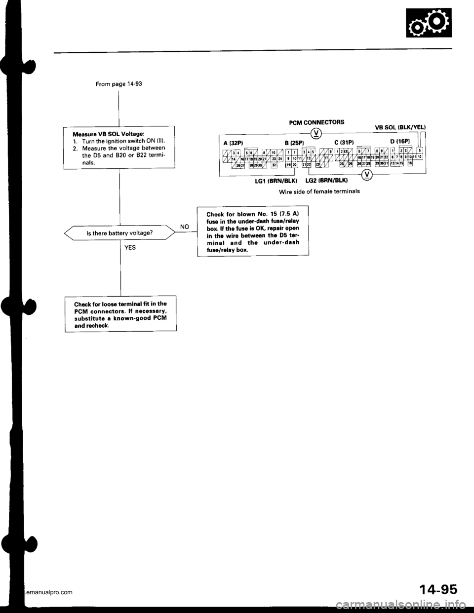
Moa3ura VB SOL Voltago:1. Turn the ignition switch ON (ll)
2. lreasure the voltage between
the D5 and 820 or 822 termi-nats.
Chock for blown No. 15 (7.5 Al
luse in tho undor-dr.h lusa/lel.Y
box. lf tho fulo i! oK, roprir op€n
in the wiro betw6on th. D5 tor'
minal and the und.r_dtahtuao/rohY box.
Chock for looto torminrl fit in the
PCM connectoJr. ll nocot3a.Y,
rubstitut. . known-good PCM
and rschock.
PCM CONNECTORS
a t32Pl B (25P1 c (31P1 D {16P1
Wire side of lemalo terminals
14-95
www.emanualpro.com
Page 612 of 1395
Electrical Troubleshooting ('98 - 00 Models)
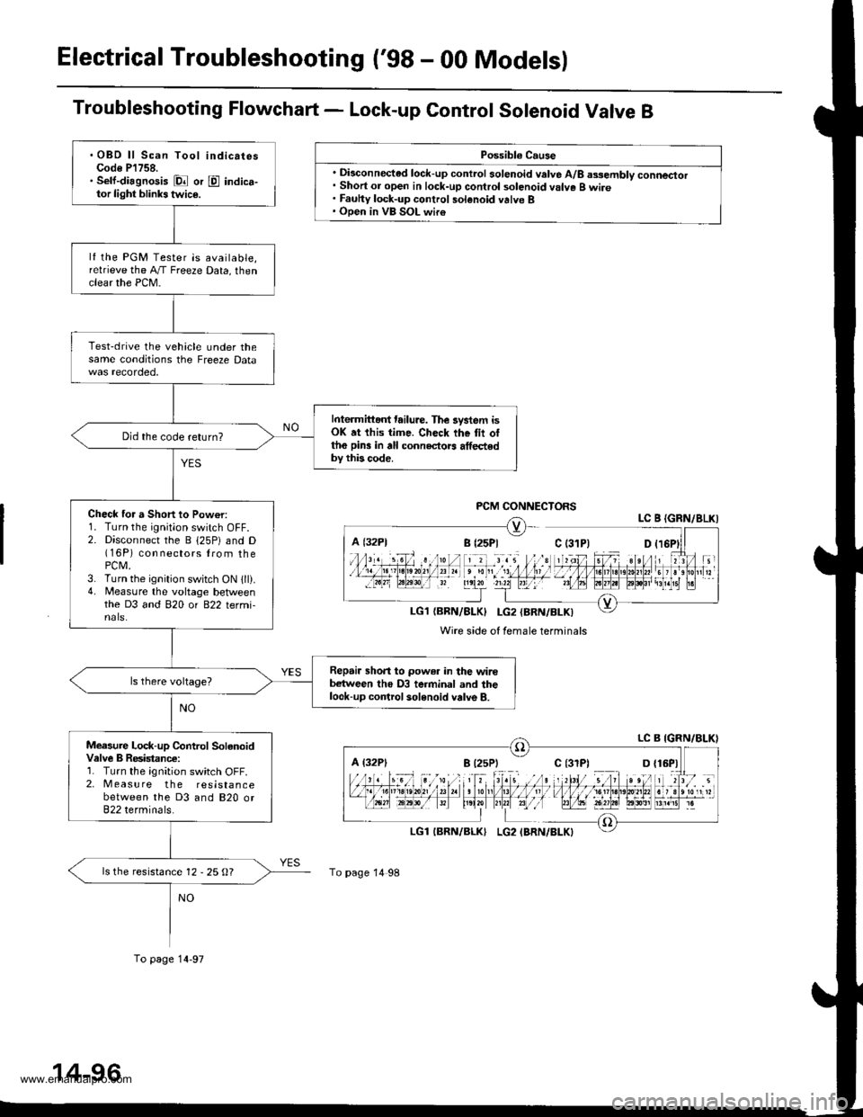
Troubleshooting Flowchart - Lock-up Control Sotenoid Valve B
Possibl€ Cause
. Disconnected lock-up control solenoid valve A/8 assembly connector. Short or open in lock-up control solenoid valve B wire. Fauhy lock-up control solenoid valve B. Open in VB SOL wir€
PCM CONNECTORSLC B {GRN/8LKI
LG1{BRN/BLK} I-G2{BRN/BLK)
Wire side of female terminals
A {32P1
To page 14 98
.OBD ll Scan Tool indicatesCode P'l758.. Sell-diagnosis Dl or E indica-tor light blinks twic€.
lf the PGM Tester is available,relrieve the A,/T Freeze Data, thenclear the PCM-
Test-drive the vehicle under thesame conditions the Freeze Data
Interm ittant tailure. The lystem isOK at this time. Check the tii ottho pin3 in all connectors athedby this code.
Did the code return?
Check for a Short to Pow€r:1. Turn the ignition switch OFF.2. Disconnect the B 125P) and D(16P) con nectors lrom thePCM.3. Turn the ignition switch ON 1ll).4. Measure the voltage betlveenthe D3 and 820 or 822 termi-nals.
Repair shon to power in the wirebetween tho D3 terminal and thelook-up control solenoid valve B.
Measure Lock-up Control SolanoidValve B Resistanc€:1. Turn the ignition switch OFF.2. Measure the resistancebetween the D3 and 820 or822 terminals.
ls the resistance 12 - 25 O?
To page 14-97
www.emanualpro.com
Page 613 of 1395
From page 14-96
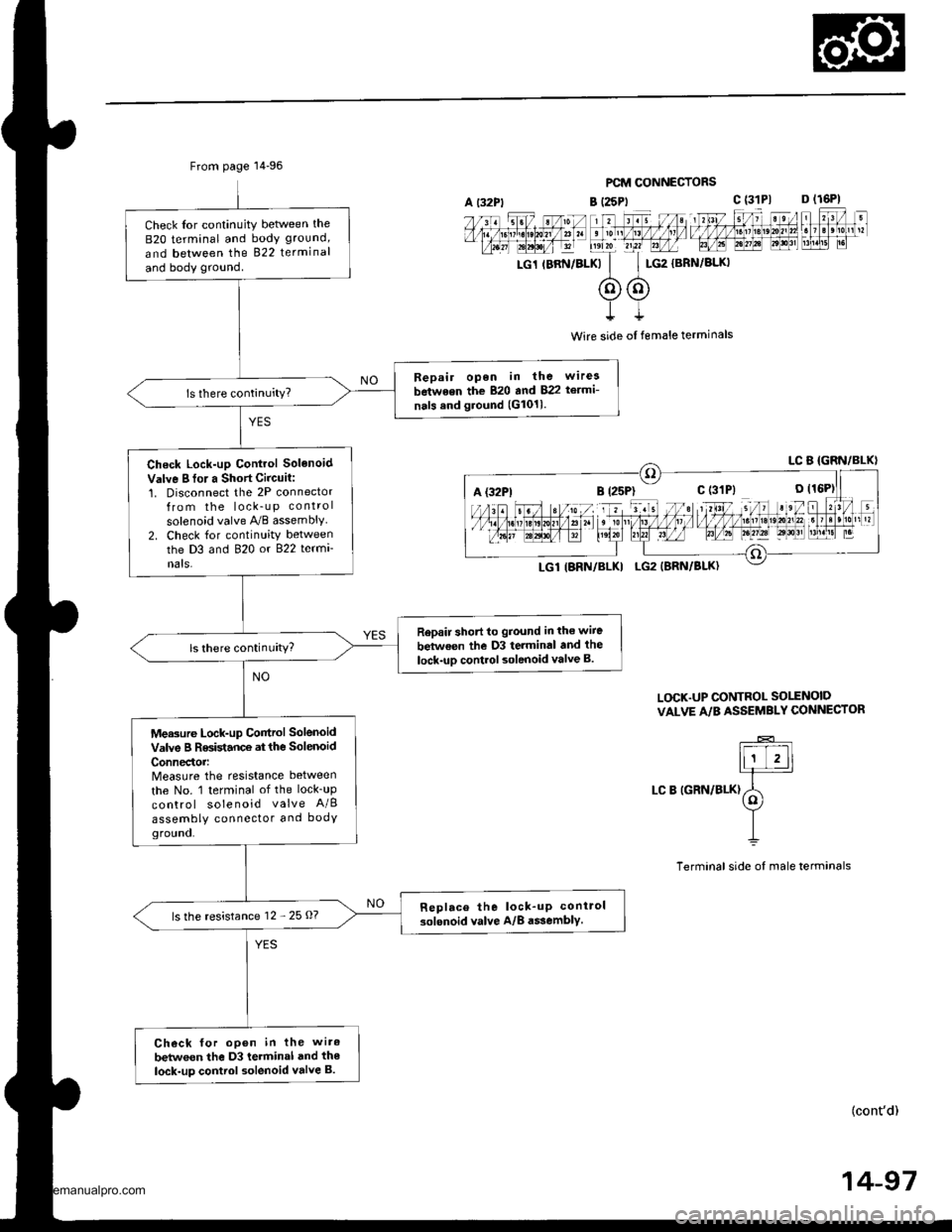
Check Ior continuity betlveen the
B2O terminal and body ground,
and between the 822 terminal
and body ground.
Bepair open in the wirea
between the 820 and 822 te.mi-
nals and ground (G1011.
Check Lock-up Control Solenoid
Valve I fo. a Short Circuit:1. Disconnect the 2P connectorfrom the lock_u p control
solenoid valve A,/B assembly2. Check for continuity betweenthe D3 and 820 or 822 termi
nats.
Rep.ir short to ground in the wiie
between the D3 terminal and the
lock-uD control solenoid valve B.ls there continuity?
Measure Lock-up Control Solenoid
valve B Resistance at the solenoid
ConnedoMeasure the resistance between
the No. 1 terminal of the lock_up
control solenoid valve A/B
assembly connector and bodYground.
Replace the lock_up conirol
solenoid valve A/8 a$embly.ls the resistance 12 - 25 O?
Check for open in the wiro
betwoen the D3 terminal and the
lock-up control solenoid valve B.
PCM CONNECTORS
B (25Pt c (31P1 D (16P1
rc1 rBRN/BLKk'
c$G2
{BRN/BLKI
t
Wire side ol female terminals
L(rcK.UP CONTROL SO1TNOID
VALVE A/B ASSEMBLY CONNECTOR
LC B IGRN/BLK)
(cont'd)
14-97
A {32P1
www.emanualpro.com
Page 616 of 1395
Electrical Troubleshooting ('98 - 00 Modelsl
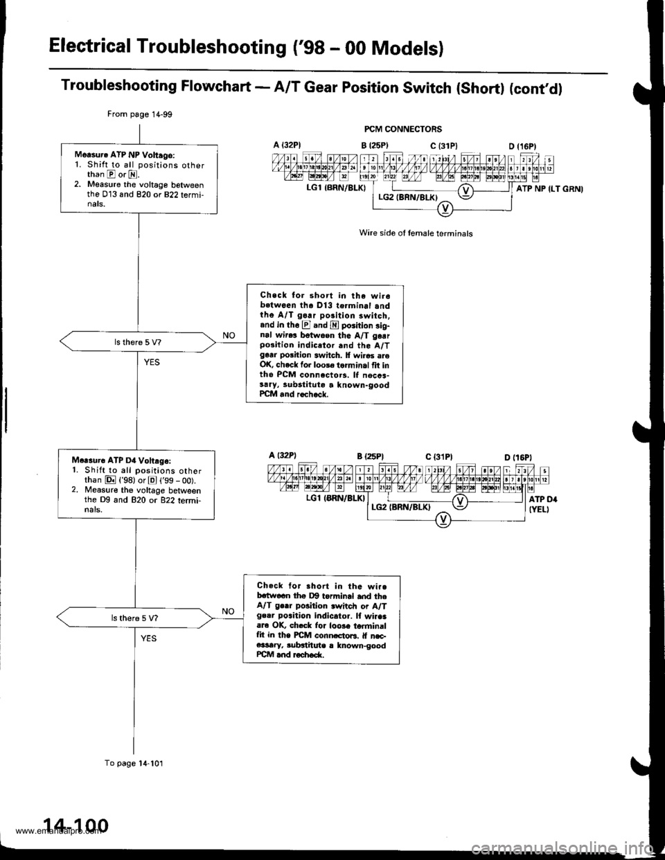
Troubleshooting Flowchart - A/T Gear position switch (short) (cont'dl
FCM CONNECTORS
B t25Plc (31P)
Wire side of lemale terminals
A t32Pl
LGl {BRN/BLK)
From page 1 4-99
To page 14-101
Measur. ATP NP Voltago:1. Shift to all positions otherthan E or E.2. Measure the voltage belweenthe 013 and 820 or 822 termi-nats.
Check for short in the wir6b.twoen tha Dl3 terminal andthe A/T go.r polition 3witch,and in th6 El and E poiition sig-nal wir.! betwoen the A/T garrpo3ition indicetor and the A/Tgarr position switch. lf wi.6s areOK, check for loole torminal fit intho PCM connccto.s, lf necca-sary, lubstituto a known-goodPCM and rocheck.
Mcrsure ATP D4 Vohrg6:1. Shift to all positions otherthan E {'98) or El ('99 - oo).2. Measure the voltage betweenthe Dg and 820 or 822 termi-nals.
Check tor Bhort in the wi..bctw6cn thg Dg torminal and theA/T ge.r position .witch or A/Tgeor poaition indicator. lf wiaaaare OK, ch.ck lor loose torminalfit in the PICM conn.cto6. lf n€c-e3sary, subgthute r lnown-goodrcM and roch6d(.
ATP NP ILT GRNI
a t32Pl
LGl IERN/BLK}
14-100
www.emanualpro.com
Page 617 of 1395
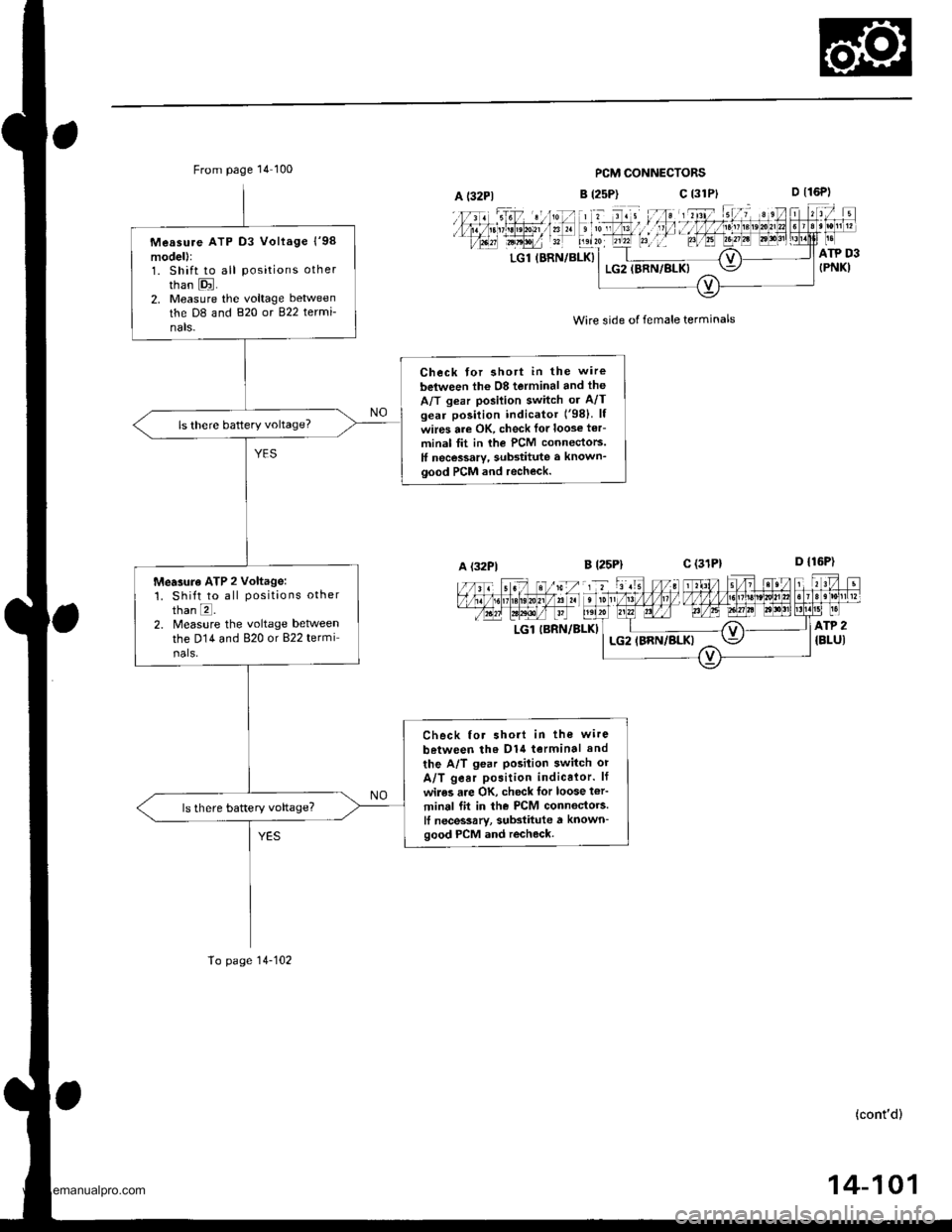
From page 14 100PCM CONNECTORS
B (2sP)c (31P}
' t d. , lll;;l';nl, :if
D t16P)
D {16P1
ATP D3{PNK)LGl (BRN/BLK}LG2IBRN/BLK)
Wire side of female terminals
B l25Plc (31P1
LGl IBRN/BLKI
A (32P1
Measure ATP D3 Vollage l'98model):1. Shift to all positions other
than E.2, Measure the voltage between
the D8 and 820 or 822 termi-
nals-
Check for shott in the wire
belween lh6 08 terminal and the
A/T gear posilion switch or A/Tgear position indicator ('98) lf
wires are OK, check lor loose ter-
minal tit in rhe PCM connectors.
ff necessary, substitute a known_good PCM and recheck.
ls there battery voltage?
Mearure ATP 2 voltage:1. Shift to all positions otherthan E.2. Measure the voltage betweenthe D14 and 820 or 822 termi
nals.
Check for short in the wire
between tho D1{ terminal and
the A/T gear posilion switch or
A/T gear position indicalor. lf
wiles are OK, check for loose t€r'
minal fit in the PCM connectors.It necessarv, substitute a known-good PCM and recheck.
To page 14-102
(cont'd)
14-101
www.emanualpro.com
Page 618 of 1395
Electrical Troubleshooting ('gg - 00 Modelsl
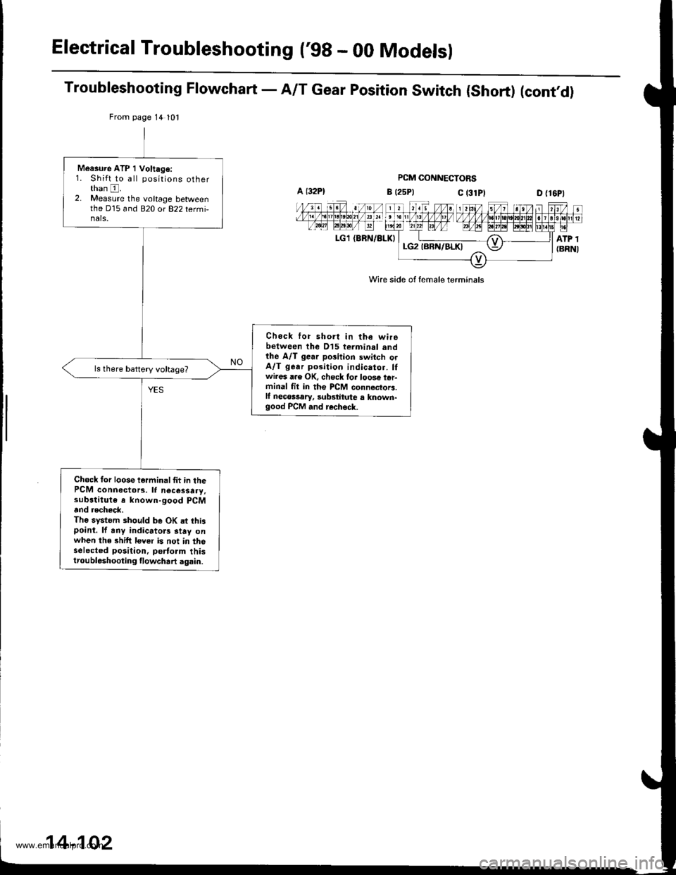
Troubleshooting Flowchart - A/T Gear position switch {short) (cont,d)
PCM CONNECTORS
B t25Ptc t3lPlD {16P1
LGl {BRN/BLK)
Wire side of female terminals
From page 14 101
Measure ATP 1 Voltag€:1. Shift to all positions otherthan E.2. Measure the voltage betweenthe D15 and 820 ot 822 tetmi-nals.
Chock lor short in the wirebetween the D15 terminal andthe A/T gear position switch orA/T gear position indicator. lfwires a.e OK, ch6ck for loos€ t6r-minal fil in tho PCM connectorc.ll neco$ary, substiiute a known-good PCM and rechsck.
Chock for loose terminalfit in thePCM connectors. lf nocessary,sub3titut€ s known-good PCMand recheck.The system 3hould be OK at thispoint. lf any indicators stay onwhen the shift lever is not in iheselect€d position, pertorm thistroubleshooting tlowchart again.
www.emanualpro.com
Page 620 of 1395
Electrical Troubleshooting ('98 - 00 Model)
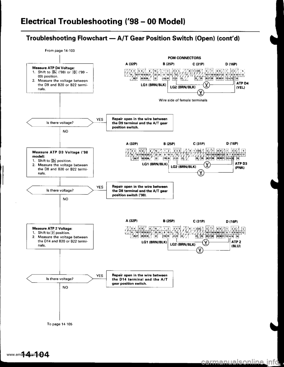
Troubleshooting Flowchart - A/T Gear Position Switch (Open) (cont'd)
PCM CONNECTORS
B {25Ptc (31P|
LGl IERN/BLKI
Wire side of female terminals
LGl {BRN/BLKI
LGl {BRN/ELXI
From page 14-103
Me.sure ATP D4 Vohrge:1. Shift to E 1'98) or E ('99 -
00) position.2. Measure the voltage betweenthe Dg and 820 or 822 termi-nats.
Repair opon in th6 wire betweentho m tarminal and the A/T gealposition swhch.
Me..ure ATP 03 Vohage l'98modell:1. Shift to E position.2. Measure the voltage betweenthe DB and 820 or 822 tetmi-nals,
Repair open in the wire botwoonth6 08 terminal .nd the A/T geatposition switch (381.
Measuro ATP 2 Voltage:1. Shilt to E position.2. Measure the voltage betweenthe D14 and 820 or 822 terminats.
Repair opon in the wire betweenthe D14 t€.minal end the A,/Tgear po3ition switch,
To page 14 105
www.emanualpro.com
Page 621 of 1395
From page 14-104
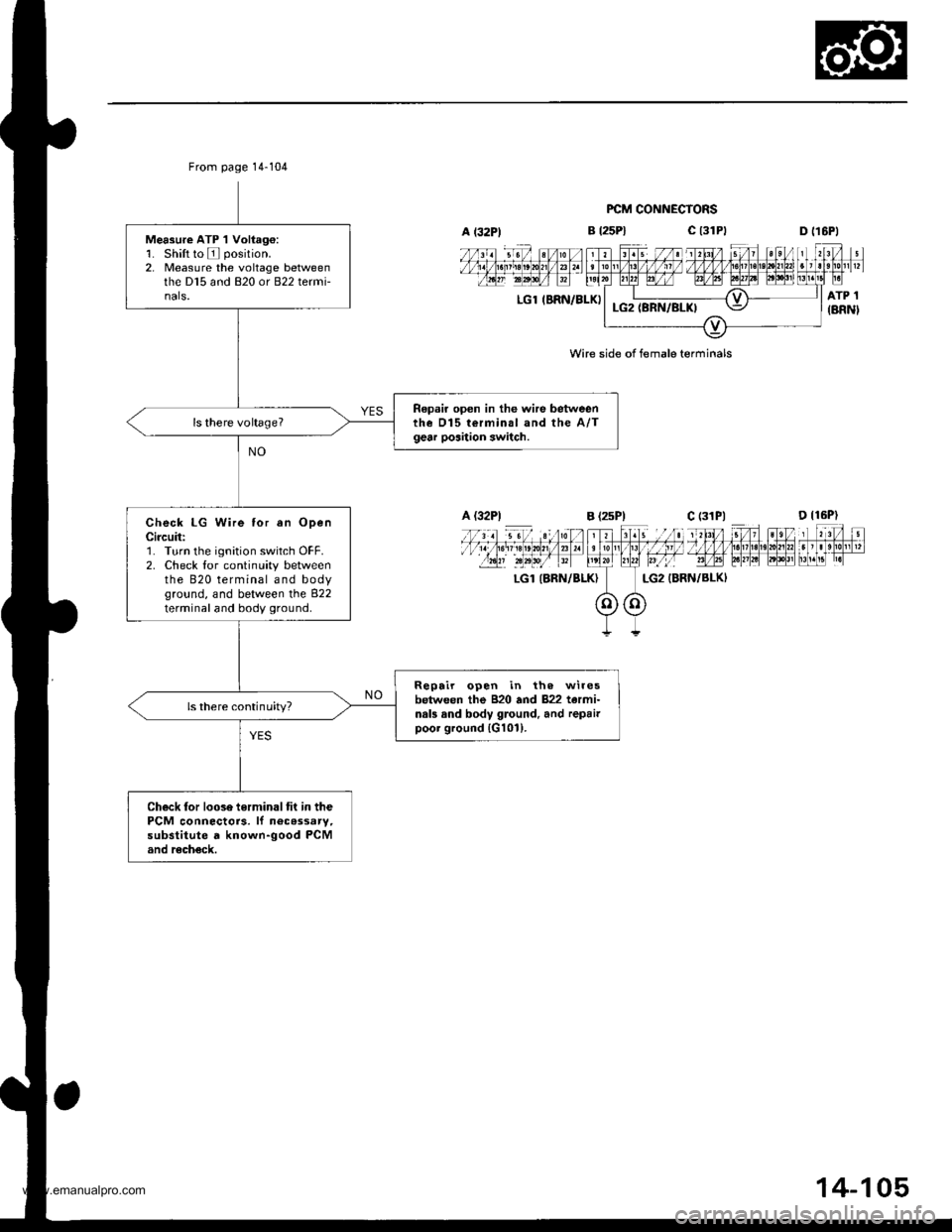
Measure ATP 1 Voliag€:1. Shift to E position.2, Measure the voltage betweenthe D15 and 820 or B22 termi-nals.
Repair open in the wire betweenthe D15 terminal and the A/Tgear poaition switch.
Check LG Wire tor an OpenCircuit:'1. Turn the ignition switch OFF.2. Check lor continuity betweenthe 820 terminal and bodyground, and between the 822terminal and body ground.
Repair open in th. wiresbetween the B20 and 822 tarmi-nals and body ground. and repairpoor ground {G101).
ls there continuity?
Check tor loose terminaltit in thePCM connectors. lf n6cassary,substitute d known-good PCMand recheck.
B t25Pl
FCM CONNECTORS
c t3lPtD tl6Pl
LGl IBRN/BLKI
LGl (BRN/BLKI
Wire side of female terminals
A (32P1B (2sP)c (31P|
14-105
www.emanualpro.com
Page 622 of 1395
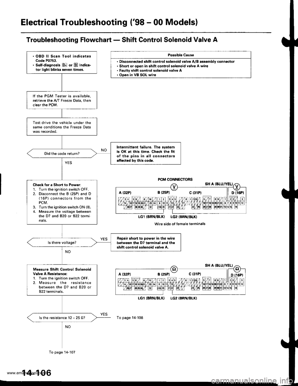
Electrical Troubleshooting ('98 - 00 Models)
Troubleshooting Flowchart - Shift Control Solenoid Valve A
Po$ible Caus€
'. Short or open in shift control solenoid valve A wire. Faulty 3hift control 3olenoid valvo A. Ooen in VB SOL wire
LGl
To page 14-108
(BRN/BLKILG2 (BRN/BLKI
A t32P) 8 {2sPl Ct3lPt ll Dll6Pt
LG1IBRN/BLKI LG2IBRN/BLK}
Wi16 side of femaleterminals
A (:l2Pl a t25Pl - c {31P}
. OBD ll Scan Tool indicatesCode P0753.. Self-diagnosis El or E indica-tor light blihk5 ievon times.
It the PGM Tester is available,retrieve the A"/T Freeze Data, thenclear th€ PCM.
Test drive the vehicle under thesame conditions the Freeze Data
Intermittent tailure. The systemb OX at this timo. Check the fito{ the pins in all connectora.ttected by this code.
Did the code return?
Ch6ck for a Short 1o Power:1. Turn the ignition switch OFF.2. Disconnect the B (25P) and D(16Pi connectors from thePCM,3. Turn the ignition switch ON (ll).
4. Measure the voltage betweenthe D7 and 820 or 822 terminals.
Repair short to power in the wirebetwoen tho D7 terminal and theshift control solenoid valve A.
Moasure Shift Control SolenoidValv6 A Resistanco:1. Turn the ignition switch OFF.2. [reasu re the resistancebetween the D7 and 820 or822 terminals.
ls the resistance l2 - 25 0?
To page 14-107
14-106
www.emanualpro.com
Page 623 of 1395
![HONDA CR-V 1998 RD1-RD3 / 1.G Owners Manual
A l32Pl
From page 14-106PCM CONNECTORS
B (25P1 C (31
LGl IERN/BLKILG2 {BRN/BLK)
Wire side of female terminals
LGl IBRN/BLK}LG2 (BRN/BLK}
SHIFT CONTROI SOLENOIDVALVE A/B ASSEMBLY CONNECTOR
IiiE-]
"*ot HONDA CR-V 1998 RD1-RD3 / 1.G Owners Manual
A l32Pl
From page 14-106PCM CONNECTORS
B (25P1 C (31
LGl IERN/BLKILG2 {BRN/BLK)
Wire side of female terminals
LGl IBRN/BLK}LG2 (BRN/BLK}
SHIFT CONTROI SOLENOIDVALVE A/B ASSEMBLY CONNECTOR
IiiE-]
"*ot](/img/13/5778/w960_5778-622.png)
A l32Pl
From page 14-106PCM CONNECTORS
B (25P1 C (31
LGl IERN/BLKILG2 {BRN/BLK)
Wire side of female terminals
LGl IBRN/BLK}LG2 (BRN/BLK}
SHIFT CONTROI SOLENOIDVALVE A/B ASSEMBLY CONNECTOR
IiiE-]
"*otrau/"aalF
I
Termanal side of male terminals
(cont'd)
14-107
c (31P)D {16P)
Check for continuity between the820 terminal and body ground.
and between the 822 terminaland body ground.
Ropair open in the wir.s betweonthe 820 and 822 terminal3 andground (G1011.
Check Shilt Control SolenoidValve A for . Short Circuit:1. Disconnect the 2P connectorfrom the shift control solenoidvalve !y'B assembly.2. Check tor continuity betweenthe D7 and B2O ot 822 tetmi-nals.
Repair short to ground in the wirebe{we€n the D7 terminal and the3hift control solonoid valvo A.ls there continuity?
Measure Shift Control SolenoidValve A Resistance at iheSolenoid Connector:Measure the resistance betweenthe No. I terminal of the shiftcontrol solenoid va lve A/Bassembly connector and bodygrou nd,
Replace the shrft control solenoidvalve A/B assembly.ls the resistance 12 25 Q?
Check for op.n in the wirebetwoon tho D7 terminal and theshift control solenoid valve A.
www.emanualpro.com