25p connector HONDA CR-V 1998 RD1-RD3 / 1.G Service Manual
[x] Cancel search | Manufacturer: HONDA, Model Year: 1998, Model line: CR-V, Model: HONDA CR-V 1998 RD1-RD3 / 1.GPages: 1395, PDF Size: 35.62 MB
Page 643 of 1395

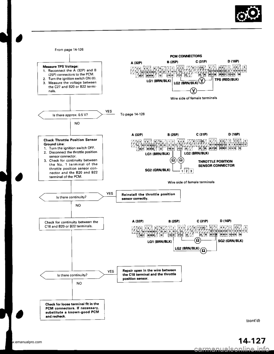
From page 14-126
Measure TPS Voltage:1. Reconnect the A (32P) and B(25P) connectors to the PCM
2. Turn the ignition switch ON (ll)
3. Measure the voltage between
the C27 and B�20 ot 822 te(mi'
nats.
ls there approx. 0.5 V?
Check Throttlo Position Sensol
Ground Line:'1. Turn the ignition switch OFF
2. Disconnect the throftle position
sensor connector.3. Check tor continuity between
tho No. 1 terminal of the
throttle position sensor con-
nector and the 820 and 822
terminsl of the PCM.
ls there continuity?
Check tor continuity betlveen the
C18 and 820 or 822 terminals
Rgpsir opan in lhe wire botween
the Cl8 torminal .nd the throttlegosiiion Sensor.ls there continuity?
Check lor looss tetminalfit in the
PCM conn€ctoia. It nece3sarY,
subslituta a known-good PCM
and .echock.
A t32Pl
To page'14-128
LG1 (BRN/BLKI
FCII CONNECTOFS
B {25P1c (31P)
LG2IBRN/BIXI
THROTTTI POSMONSENSOR CONNECTOR
SG2 IGRN/BLK}rL2l3t
Wire side of female terminals
B {25P1c l3lPl D (16P1
LGl IBRN/BLKISG2 {GRN/BLK}
n l,I-il nFFFTI,T';T;IEFML"| -
(cont'd)
wire side of female terminals
LGl IBRN/BIXI
14-127
www.emanualpro.com
Page 647 of 1395

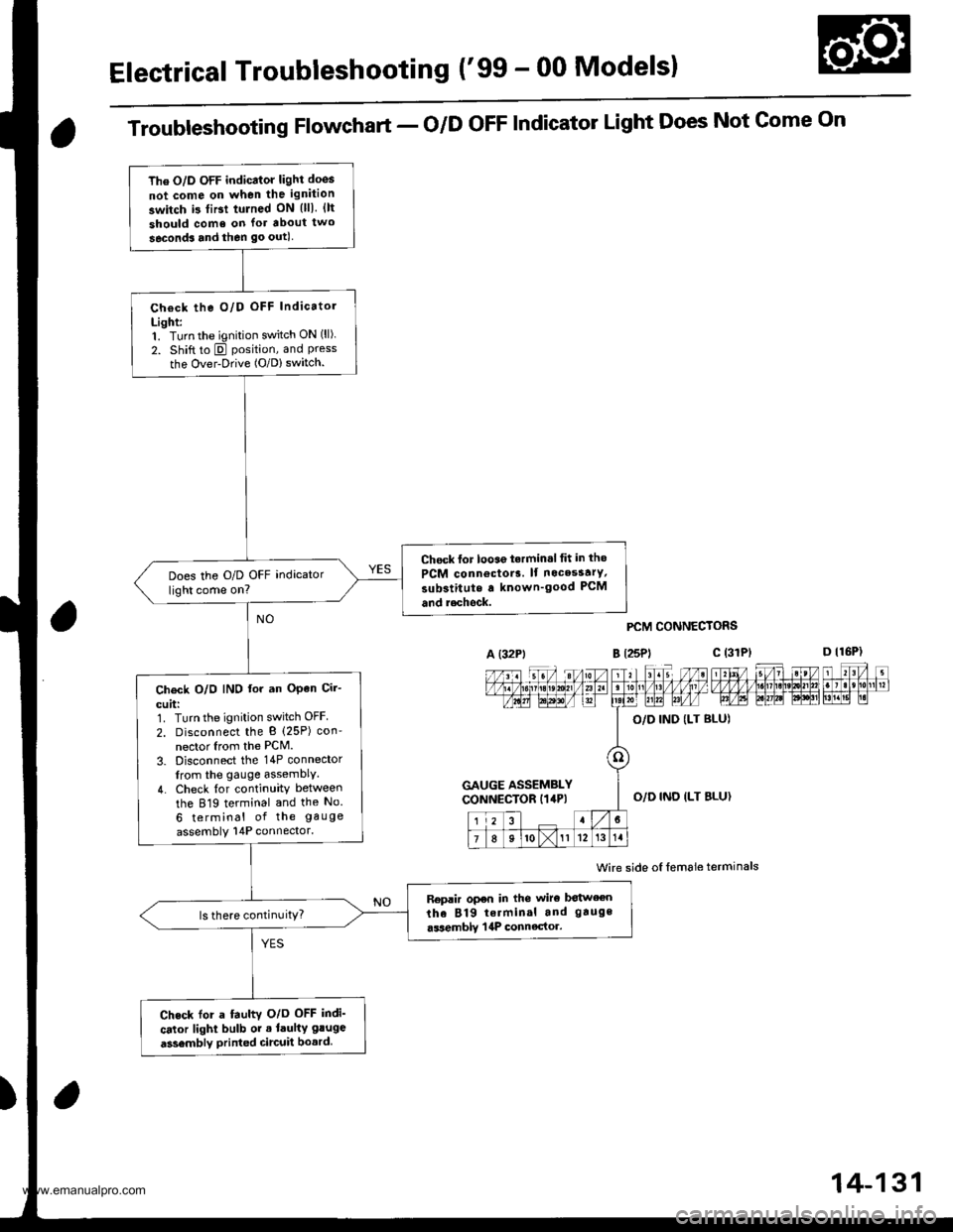
Electrical Troubleshooting ('99 - 00 Modelsl
The O/D OFF indicator light doos
not come on when the ignition
switch i3 tiBt tulned ON {lll. {lt
should come on lor about two
seconds and then go outl
Check the O/D OFF Indicatol
Light:1. Turn the ignition switch ON (ll).
2. Shift to E position, and Pressthe Over-Drive (O/D) switch.
Chock lor looae t.rmin.l tit in tho
PCM connoctor3. lf nocesstrY,
substitute a known'good PCM
and r.chock.
Does the O/D OFF indicator
light come on?
Ch€ck O/O IND lor an OPen Cir-
cuit:1. Turn the ignition switch OFF
2. Disconnect the B (25P) con'
nector Irom the PCM.
3. Disconnect the 14P connector
from the gauge assemblY.
4. Check {or continuity between
the 819 terminal and the No.
6 terminal of the gauge
assembly 14P connector.
Replir open in the wiro botween
the 819 terminal and gauge
.ssemblY | 4P connector.ls there continuitY?
Check for a fauhv O/o OFF indi'
cator light bulb or . laulty gluge
a3sembly printed circuit bo.rd.
Troubleshooting Flowchart - o/D oFF Indicator Light Does Not Gome On
A (32Pt
PCM CONNECTORS
B t25Pl c (31
Wire side oI lemale terminals
a
c (3rPt
GAUGE ASSEMBLYCONNECTOR I14P)O,/D IND ILT BLU}
14-131
www.emanualpro.com
Page 649 of 1395

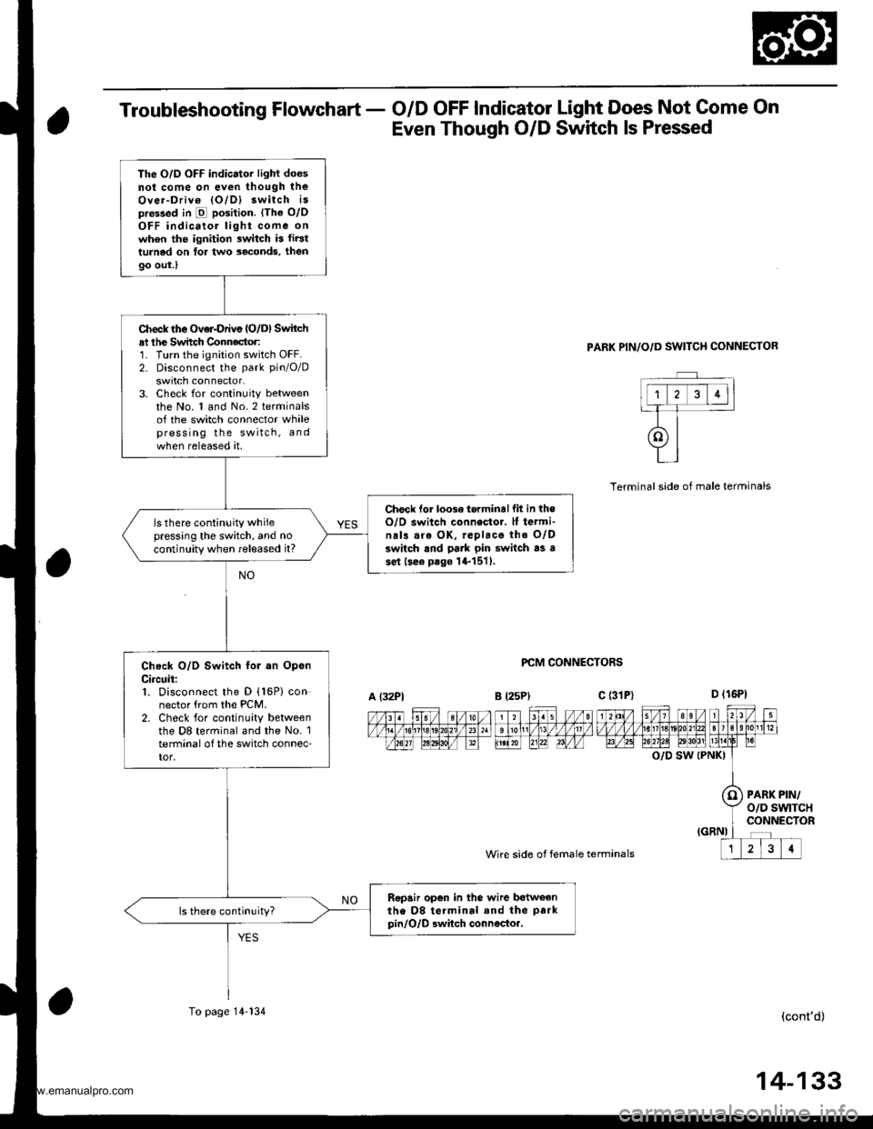
Troubleshooting Flowchart - O/D OFF Indicator Light Does Not Come On
Even Though O/D Switch ls Pressed
PARK PIN/O/D SWITCH CONNECTOR
PCM CONNECTORS
Wire side of female termanals
Terminalside of male terminals
O/D SW (PNKI
PARK PIN/o/D swtTcHCONNECTOR
(cont'd)
The O/D OFF indicator light doesnot come on ev€n though theOver-Driv6 lO/Dl 3witch ispre$ed in E position. lThe o/oOFF indicatol light come onwh6n the ignition switch is fir3tturned on tor two seconds, then
9o out.l
Check the Over-Drivs {O/D) Switchal lhe Switch Connector:1. Turn the ignition switch OFF.2. Disconnect the park pin/O/D
swrtch connector.3. Check for continuity betweenthe No. 1 and No.2 terminalsof the switch connector whalepress ing the switch, andwhen released at.
Check lor loose torminallit in theO/O switch connestor. lf termi-na13 are OK, replace the O/Dswitch and pa]k pin switch as ase.t lsee p.go l+1511.
ls there continuity whilepressing the switch, and no
continuity when released it?
Check O/D Switch fol an OpsnCircuit:1. Disconnect the D (16P) connector from the PCM.2. Check for continuity betweenthe D8 terminal and the No. 1terminal o{ the switch connec'tor,
Ropair open in the wire batweanthe D8 te.minal and the park
pin/O/D Bwhch connocto..
A {32P1B l25Plc (31P)
To page 14-134
14-133
www.emanualpro.com
Page 673 of 1395

Road Test
NOTE: Warm up the engine to normal operating temperature (the radiator tan comes on).
1. Before testing, check the transmission fluid level, see page 14-160.
2. Apply the parking brake and block the wheels. start the engine, then shift to E {'97 - 98) or E {'gg - 00) position
while pressing the brake pedal. Press the accelerator pedal and release it suddenly. The engine should not stall.
3. Repeat same test in E position ('97 - 98 models).
4. Test-drive the vehicle on a flat road in the E or E position. Check that the shift points occur at approximate speeds
shown on a flat road. Also check for abnormal noise and clutch slippage.
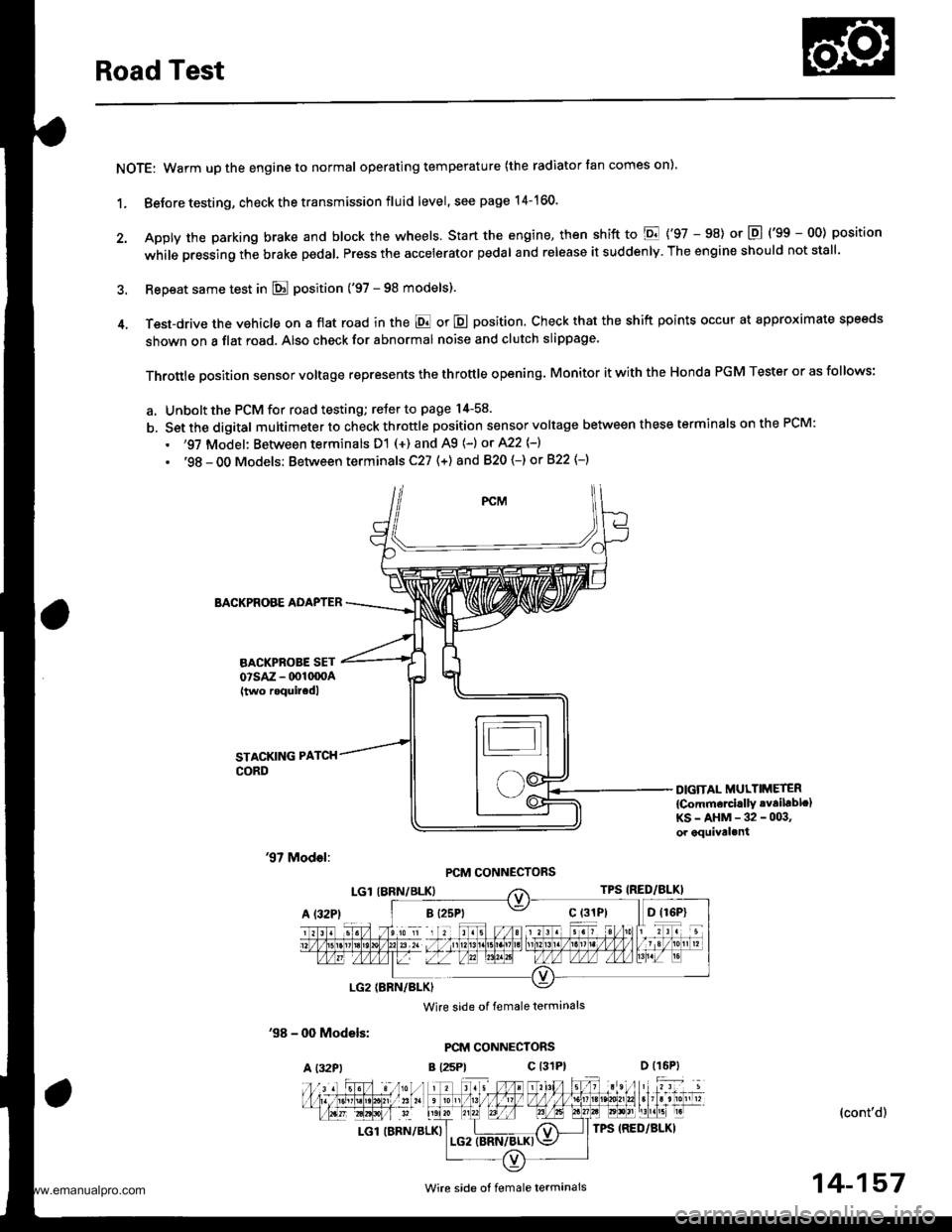
Throttle position sensor voltage represents the throttle opening. Monitor it with the Honda PGM Tester or as follows:
a. Unbolt the PCM for road testing; reJer to page 14-58.
b. Set the digital multimeter to check throttle position sensor voltage between these terminals on the PCM:
. '97 Model: Between terminals D'! (+) and A9 (-) or A22 {-}
. '98 - OO Models; Between terminals C27 (+) and 820 (-) or 822 {-)
BACKPROBE ADAPTER
BACKPROBE SETorsAz - 001moA(two roquircdl
STACKING PATCH
CORD
DIGiTAL MULTIMETER
{Comm€rcirllY .vailablc}KS-AHM-32-003,or equival.nt
'97 Model:PCM CONNECTORS
'98 - 0O Models:
A l32Pt
Wire side of female terminals
PCM CONNECTORS
B {25Pt c l31P}
(cont'd)
LGl (BRN/BLK)
'. //B 1 l'o ti , jl. to a 2r / / 11111t1.t nait la t1 t213tr / t6t, tl / / / / 1 3 / 10n v
t-'a:IM-&E -Llfiffi-fl)\"".'E
Wire side ot female termanals14-157
www.emanualpro.com