Power steering HONDA CR-V 1998 RD1-RD3 / 1.G Owner's Manual
[x] Cancel search | Manufacturer: HONDA, Model Year: 1998, Model line: CR-V, Model: HONDA CR-V 1998 RD1-RD3 / 1.GPages: 1395, PDF Size: 35.62 MB
Page 852 of 1395
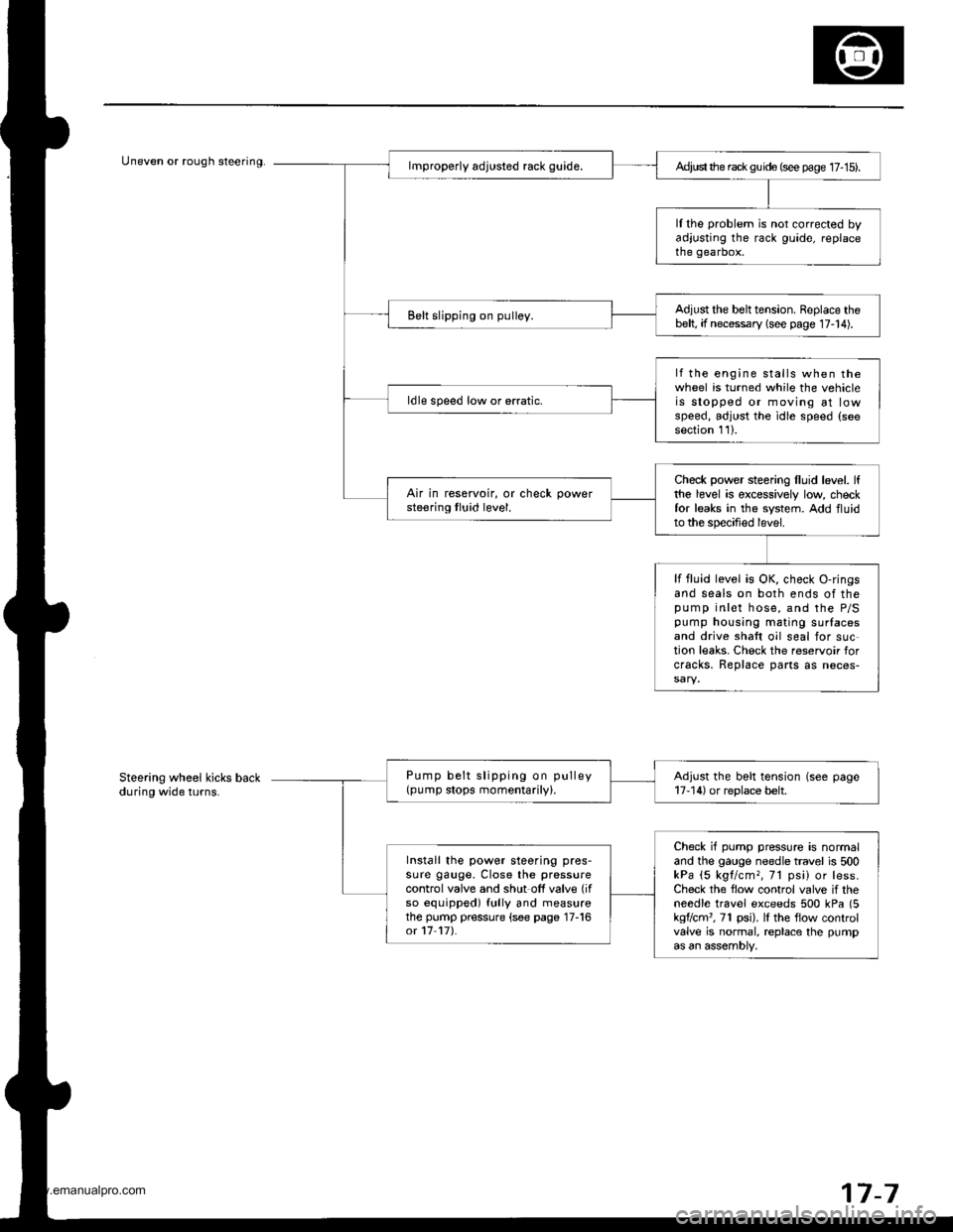
Uneven or rough steering.Ad,ust the rack gu ide (see page 17- 15).
ll the problem is not corrected byadjusting the rack guide, replacethe gearbox.
Adjust the belttension. Replace thebelt, if necessary (see page 17-14).Belt slipping on pulley.
lf the engine stalls when thewheel is turned while the vehicleis stopped or moving at lowspeed, adjust the idle speed (seesection 111.
ldle speed low or erratic.
Check power steering lluid level. lfthe level is excessively low checkfor leaks in the system. Add fluidto the specified level.
Air in reservoir, or check powersteering tluid level.
lf fluid level is OK, check O-ringsand seals on both ends of thepump inlet hose, and the P/Spump housing mating surlacesand drive shaft oil seal for suction leaks. Check the reservoir forcracks, Replace parts as neces-
Pump belt slipping on pulley(pump stops momentarily).Adjust the belt tension (see page17-14) or replace belt.
Check if pump pressure is normaland the gauge needle travel is 500kPa (5 kgl/cm,, 71 psi) or less.Check the flow control valve if theneedle travel exceeds 500 kPa (5kgflcm'�, 71 psi). lI the flow controlvalve is normal, replace the pumpas an assembly,
Install the power steering pres-sure gauge, Close the pressurecontrol valve and shut off valve (if
so equipped) fully and measurethe pump pressure (see page 17-16ot 17 17).
Steering wheel kicks backduring wide turns.
7-7
www.emanualpro.com
Page 857 of 1395
Inspection and Adjustment
Steering Operation
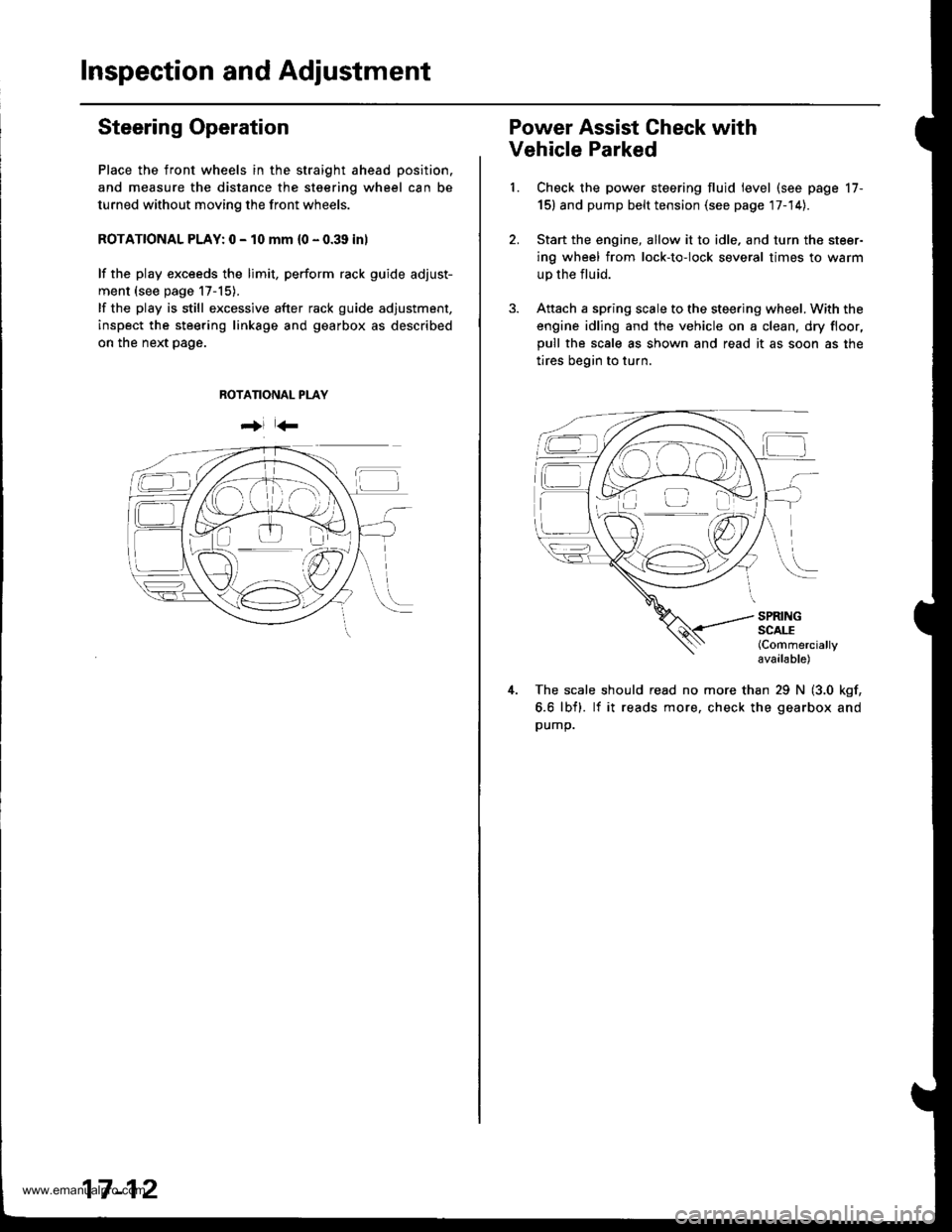
Place the front wheels in the straight ahead position.
and measure the distance the steering wheel can be
turned without moving the front wheels.
ROTATIONAL PLAY: 0 - 10 mm (0 - 0.39 inl
lf the play exceeds the limit, perform rack guide adjust-
ment (see page 17-15).
lf the play is still excessive after rack guide adjustment,
inspect the steering linkage and gearbox as described
on the next page.
ROTANONAL PLAY
+i r
17-12
Power Assist Check with
Vehicle Parked
1. Check the power steering fluid level (see page 17-
15) and pump belt tension (see page 17-14).
2. Start the engine, allow it to idle, and turn the steer-
ing wheel from lock-toiock several times to warm
up the fluid.
3. Aftach a spring scale to the steering wheel, With the
engine idling and the vehicle on a clean. dry floor,
pull the scale as shown and read it as soon as the
tires begin to turn.
SPRINGSCALE(Commercially
available)
The scale should read no more than 29 N (3.0 kgf,
6.6 lbfl. lf it reads more, check the gearbox and
oumo.
f::1-tE
www.emanualpro.com
Page 859 of 1395
Inspection and Adjustment
Pump Belt
When using a new belt. first adjust the deflection or ten-
sion to the values for the new belt, then readjust the
deflection or tension to the values for the used belt after
running engine for five minutes.
Inspection
Note these items during inspection:
a lf there are cracks or any damage evident on the belt,
replace it with a new one.
. Follow the manufacturer's instructions lor the tension
gauge.
'1. Remove the P/S reservoir from the bracket, and set
it aside.
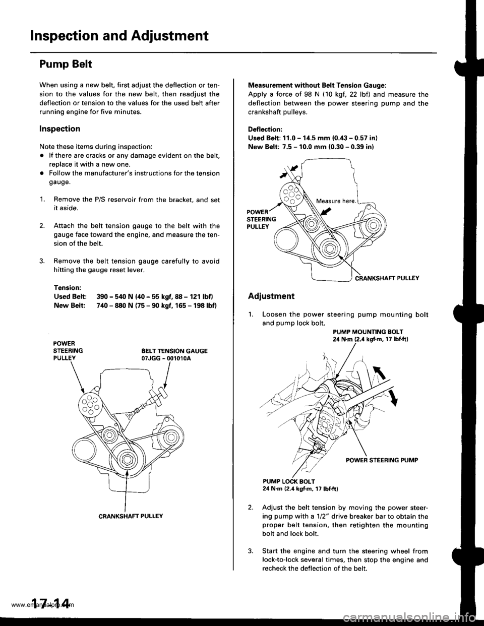
2. Attach the belt tension gauge to the belt with the
gauge face toward the engine, and measure the ten-
sion of the belt.
Remove the belt tension gauge carefully to avoid
hitting the gauge reset lever.
Tension:
Used Belt: 390 - 540 N {40 - 55 kgf, 88 - 121 lbf)
New Belt: 7,[0 - 840 N (75 - 90 kgf, 165 - 198 lbf)
CRANKSHAFT PULLEY
17-14
Measurement without Belt Tension Gauge:
Apply a force ot 98 N (10 kgf,22 lbt) and measure the
deflection between the power steering pump and the
crankshaft oullevs.
Deflection:
Used Belt: 11.0 - 1i1.5 mm {0.'(l - 0.57 in)
New Belt: 7.5 - 10.0 mm {0.30 - 0.39 in)
CRANKSHAFT PULLEY
Adiustment
'1. Loosen the power steering pump mounting bolt
and pump lock bolt.
PUMP MOUNNNG BOLT24 N'm (2.4 kgf'm, 17 lbf ftl
PUMP LOCK BOLT24 N.m 12.4 kgf.m, 17 lbf.ftl
Adjust the belt tension by moving the power steer-
ing pump with a 1/2" drive breaker bar to obtain theproper belt tension, then retighten the mounting
bolt and lock bolt.
Start the engine and turn the steering wheel from
lock-to-lock several times, then stop the engine and
recheck the deflection of the belt.
Measure here.
www.emanualpro.com
Page 860 of 1395
Rack Guide Adjustment
1.
6.
7.
5.
4.
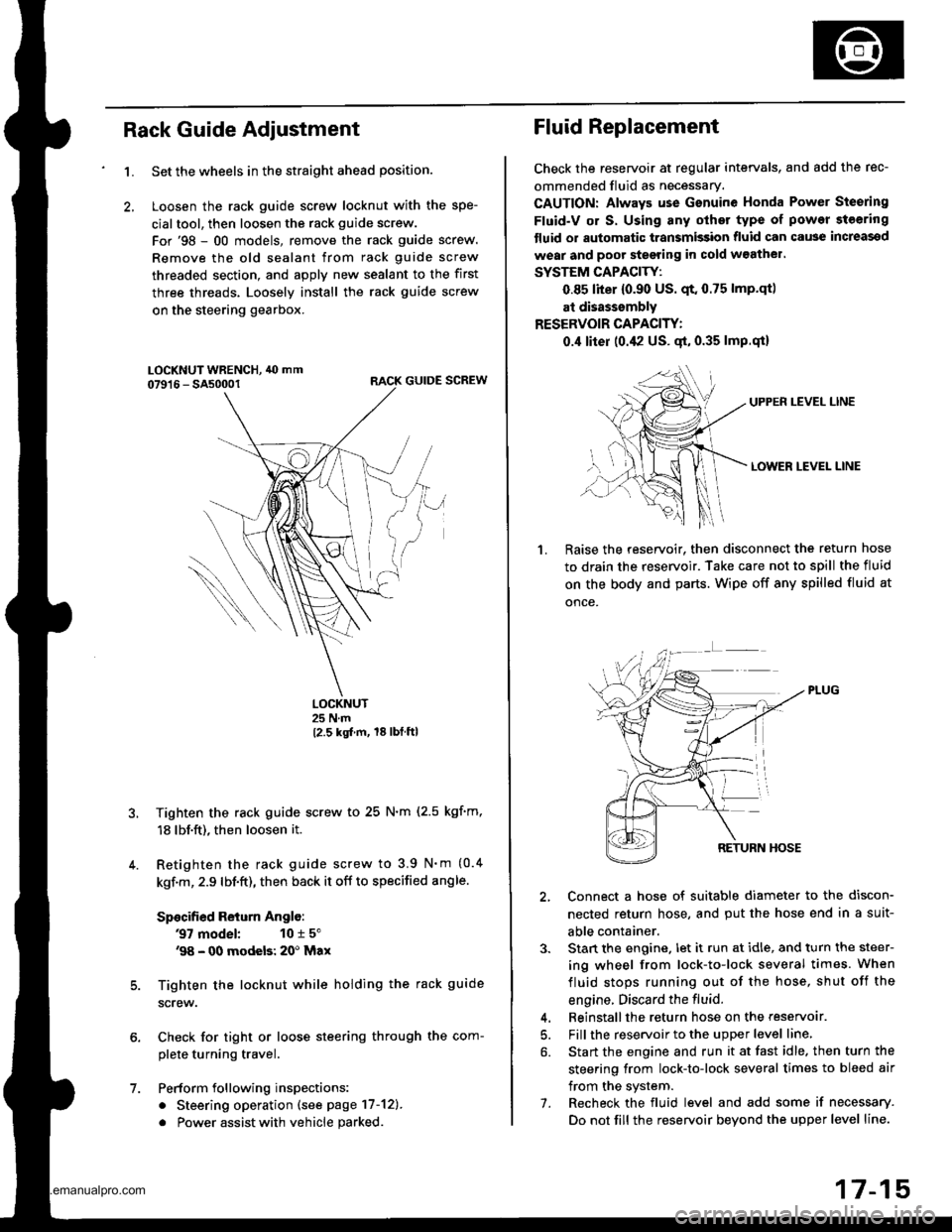
Set the wheels in the straight ahead position.
Loosen the rack guide screw locknut with the spe-
cialtool, then loosen the rack guide screw.
For'98 - 00 models, remove the rack guide screw.
Remove the old sealant from rack guide screw
threaded section, and apply new sealant to the first
three threads. Loosely install the rack guide screw
on the steering gearbox.
RACK GUIDE SCREW
LOCKNUT25 N.m
12.5 kgt m, 18lbtftl
Tighten the rack guide screw to 25 N.m (2.5 kgf'm,
18 lbf.ft), then loosen it.
Retighten the rack guide screw to 3.9 N'm (0.4
kgf.m, 2.9 lbf.ft), then back it off to specified angle.
Specified Return Anglo:
37 model: 10 r 5"'98 - 00 modeb: 20' Max
Tighten the locknut while holding the rack guide
screw.
Check for tight or loose steering through the com-
plete turning travel.
Perform following inspections:
. Steering operation (see page 17-12).
. Power assist with vehicle parked
Fluid Replacement
Check the reseryoir at regular intervals, and add the rec-
ommended fluid as necessary.
CAUTION: Always use Gsnuine Honda Power Steering
Fluid-V or S. Using any other type of power steering
tluid or automatic transmission fluid can cause increassd
wear and poor steering in cold w3athel.
SYSTEM CAPACITY:
0.85 liter {0.90 US. qt. 0.75 lmp.qtl
at disasssmbly
RESERVOIR CAPACITY:
0.,1 liter (0.42 US. gt, 0.35 lmp.qi)
UPPEN LEVEL LINE
LOWER LEVEL LINE
1.Raise the reservoir. then disconnect the return hose
to drain the reservoir. Take care not to spill the fluid
on the body and parts. Wipe off any spilled fluid at
once.
2, Connect a hose of suitable diameter to the discon-
nected return hose, and put the hose end in a suit-
able container.
3. Stan the engine. let it run at idle, and turn the steer-
ing wheel from lock-to-lock several times. When
fluid stops running out of the hose, shut off the
engine. Discard the fluid.
4. Beinstallthe return hose on the reservoar.
5. Fill the reservoir to the upper level line,
6. Start the engine and run it at fast idle. then turn the
steering from lock-to-lock several times to bleed air
from the system.
7. Recheck the fluid level and add some if necessary.
Do not fill the reservoir beyond the upper level line.
www.emanualpro.com
Page 862 of 1395
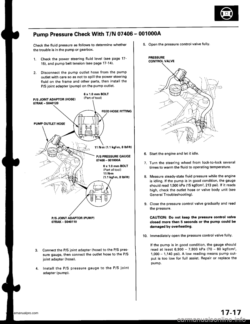
Pump Pressure Check With T/N 07406 -
Check the fluid pressure as follows to determine whether
the trouble is in the pump or gearbox.
1. Check the power steering tluid level (see page 17-
151, and pump belt tension (see page 17-14).
2. Disconnect the pump outlet hose from the pump
outlet with care so as not to spill the power steering
fluid on the frame and other parts, then install the
P/S joint adapter (pump) on the pump outlet.
6 x 1.0 mm BOLT(Part oftool)
FEED HOSE HfNNG
PUMP OUTLET HOSE
1'l N.m 11.1 kgf.m,8lbf ft)
P/S PRESSURE GAUGE07406 - 001000A
6 x 1.0 mm BOLT(Part ol tool)11 N.m(1.r kg{.m,8lbf'ft|
Connect the P/S joint adapter (hose) to the P/S pres-
sure gauge, then connect the outlet hose to the P/S
joint adapter (hose).
Install the P/S pressure gauge to the P/S joint
adapter (pumpl.
001000A
5. Open the pressure controlvalve fully.
PRESSURECONTROL VALVE
7.
10.
Start the engine and let it idle.
Turn the steering wheel from lock-to-lock several
times to warm the tluid to operating temperature.
Measure steady-state fluid pressure while the engine
is idling. It the pump is in good condition, the gauge
should read 1,500 kPa (15 koflcm'�,213 psi). lf it reads
high. check the outlet hose or valve body unit {see
General Troubleshooting),
Close the-pressure control valve gradually and read
the oressure.
CAUTION: Do not keep the pressurs control valve
closed more then 5 seconds or the pump could bo
damaged by overheating.
lmmediately open the pressure controlvalve fully.
lf the pump is in good condition, the gauge should
read at least 6,900 - 7;800 kPa (70 - 80 kgflcm'�,
1,000 - 1.140 psi), A low reading means pump out-
Dut is too low for {ull assist. Repair or replace the
oumo.
17-17
www.emanualpro.com
Page 868 of 1395
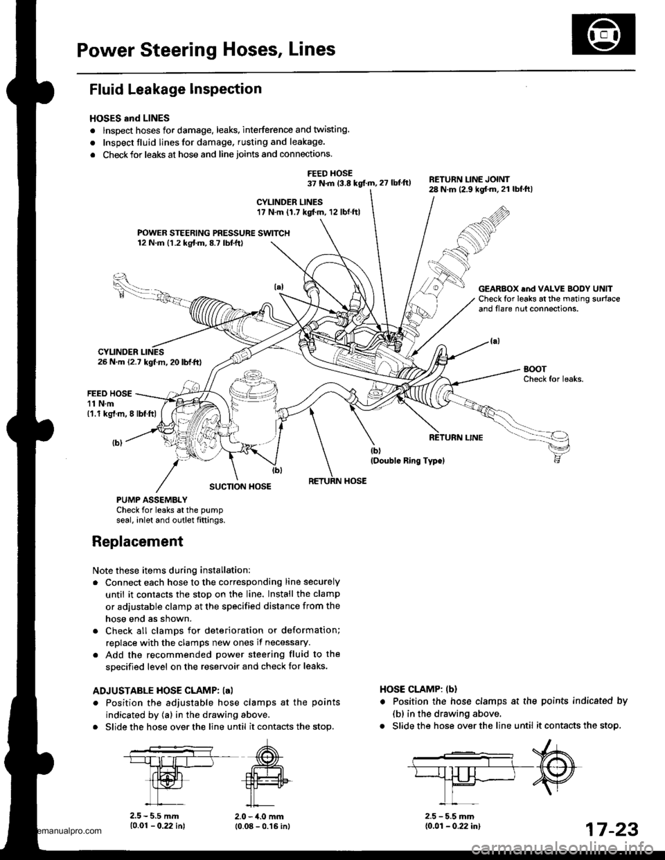
Power Steering Hoses, Lines
Fluid Leakage Inspection
HOSES and LINES
. lnspect hoses for damage. leaks. interference and twisting
. Inspect fluid linesfor damage, rusting and leakage.
. Check for leaks at hose and line joints and connections.
FEED HOSE37 N.m 13.8 kgf.m, 27 lbtft)RETURN LINE JOINT28 N.m (2.9 kgf.m.21 lbf.ftl
CYLINDER LINES17 N.m (1.7 kgf.m. 12 lbf.ftl
FOWER STEERING PRESSURE SWITCH12 N.m (1.2 kgf.m,8.7 lbtft)
26 N.m (2.7 kgf.m, 20 lbf.ft)
GEARBOX .nd VALVE BODY UNllCheck for leaks at the mating surfaceand flare nut connections.
CYLINDER
FEED HOSE11 N.m('1.1 kgt.m, 8 lbf.ftl
SUCTION HOSE
PUMP ASSEMBLYCheck for leaks atthe pump
seal. inlet and outlet fittings.
Note these items during installation:
. Connect each hose to the corresponding line securely
until it contacts the stop on the line. Install the clamp
or adjustable clamp at the specified distance from the
hose end as shown.
. Check all clamDs for deterioration or deformation;
replace with the clamps new ones if necessary.
. Add the recommended power steering fluid to the
specified level on the reservoir and check for leaks.
ADJUSTABLE HOSE CLAMP: la)
. Position the adjustable hose clamps at the points
indicated by (a) in the drawing above.
. Slide the hose over the line until it contacts the stop.
HOSE CLAMP: lbl
. Position the hose clamps at the
(b) in the drawing above.
. Slide the hose over the line until
Replacement
10.01 - 0.22 in)
points indicatsd by
it contacts the stop,
2.0 - 4.0 mm10.08 - 0.16 inl2.5 - 5.5 mm{0.01 - 0.22 in}17 -23
www.emanualpro.com
Page 869 of 1395
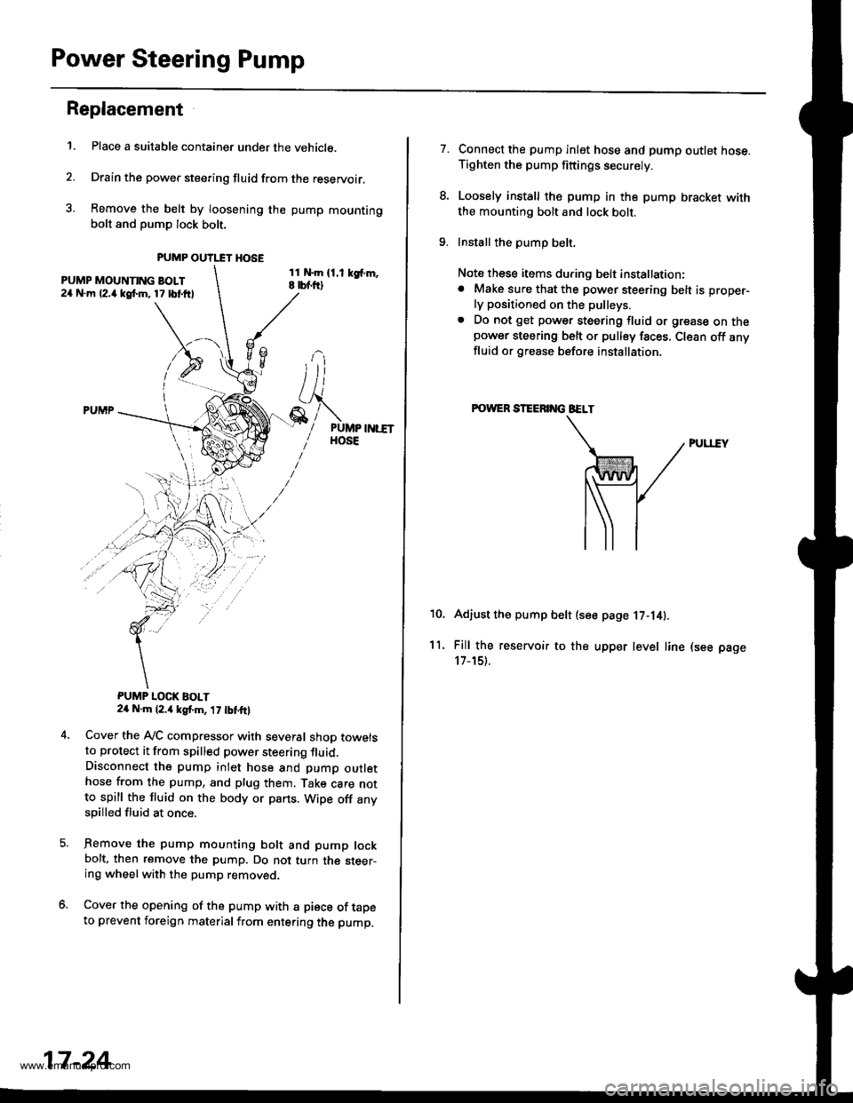
Power Steering Pump
Replacement
1.Place a suitable container under the vehicle.
Drain the power steering fluid from the reservoir.
Remove the belt by loosening the pump mountingbolt and pump lock bolt.
PUMP MOUNNNG BOI.T24 N.m 12.4 kgt m, 17 lbl.ftl
PUMP LOCK BOLT24 N.m (2.4 kg{.m, 1, tbfttl
Cover the IVC compressor with several shop towelsto protect it from spilled power steering fluid.Disconnect the pump inlet hose and pump outlethose from the pump, and plug them. Take care notto spill the lluid on the body or parts. Wipe off anyspilled fluid at once.
Remove the pump mounting bolt and pump lockbolt, then remove the pump. Do not turn the steer-ing wheelwith the pump removed.
Cover the opening of the pump with a piece of tapeto prevent foreign materialfrom entering the pump.
PUMP OU'I.TT HOSE
11 N.m (1.1 kgf.m,E rbf.ti)
17-24
7.Connect the pump inlet hose and pump outlet hose.Tighten the pump fittings securely.
Loosely install the pump in the pump bracket withthe mounting bolt and lock bolt.
Install the pump belt.
Note these items du.ing belt instsllation:. Make sure that the power steering belt is proper-
ly positioned on the pulleys.
. Do not get power steering fluid or grease on thepower steering belt or pulley faces, Clean off anyfluid or grease before installation
FOWER STEER G EELT
PUTrlY
Adiust the pump belt (see page 17-141.
Fill the reservoir to the upper level line (see page't7 -151..
10.
'l l.
www.emanualpro.com
Page 870 of 1395
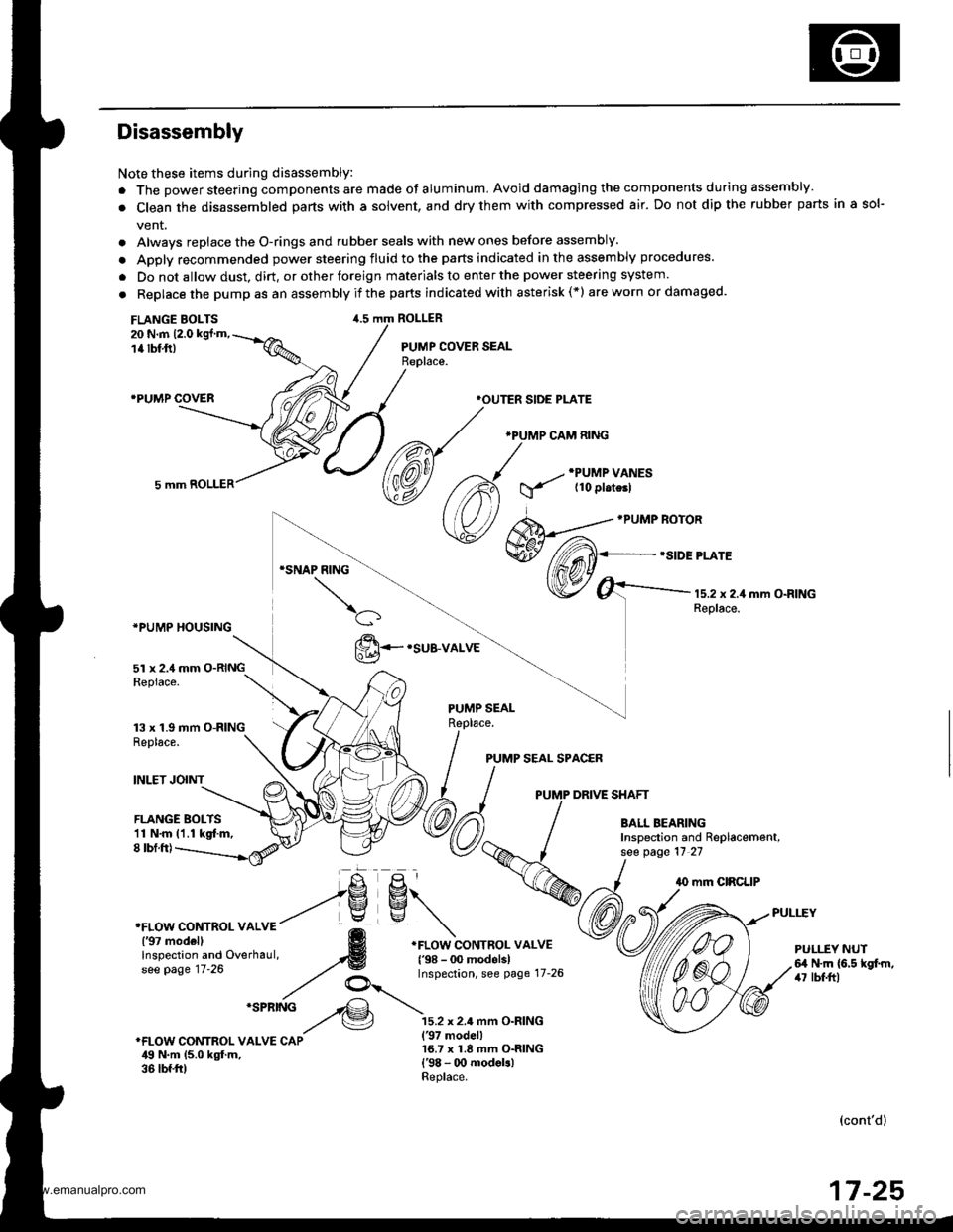
Disassembly
Note these items during disassembly:
. The power steering components are made of aluminum, Avoid damaging the components during assembly.
. Clean the disassembled parts with a solvent, and dry them with compressed air. Do not dip the rubber parts in a sol-
vent.
. Always replace the O-rings and rubber seals with new ones before assembly.
. Apply recommended power steering fluid to the parts indicated in the assembly procedures.
. Do not allow dust, dirt, or other foreign materials to enter the power steering system.
. Replace the pump as an assemblyif the parts indicated with asterisk(*) areworn ordamaged.
FLANGE BOLTS20 N.m 12.0 kgt'm,
1a tbf,ft)
.PUMP COVER
ROLLER
PUMP COVER SEAL
*PUMP HOUSING
5l x 2.4 mm O-RINGRepiace.
13 x 1.9 mm O-RINGReplace.
INLET JOINT
*OUTER SIDE PLATE
.PUMP CAM RING
PUMP SEAL SPACER
PUMP DRIVE SHAFT
FLANGE BOLTS11 N.m 11.1 kgt m,8 tbf.ft)
PULI.-EY NUTfl N.m (6.5 kgf.m,/r7 lbf.ftl
(cont'd)
17 -25
www.emanualpro.com
Page 871 of 1395
Power Steering Pump
Disassembly (cont'dl
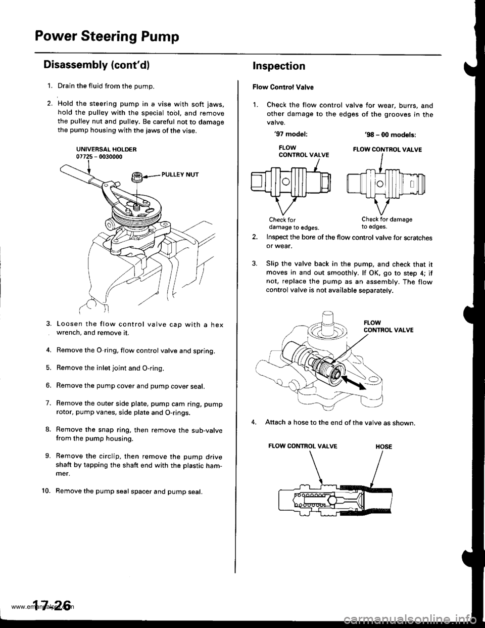
1.
7.
9.
10.
Drain the fluid from the pump.
Hold the steering pump in a vise with soft jaws.
hold the pulley with the special tool, and remove
the pulley nut and pulley. Be careful not to damagethe pump housing with the jaws of the vise.
UNIVERSAL HOLDER07725 - 0030000
Loosen the flow control valve cap with a hexwrench, and remove it.
Remove the O,ring, flow control valve and spring.
Remove the inlet joint and O-ring.
Remove the pump cover and pump cover seal.
Remove the outer side plate, pump cam ring, pump
rotor, pump vanes, side plate and O-rings.
Remove the snap ring, then remove the sub-valvefrom the pump housing.
Remove the circlip, then remove the pump driveshaft by tapping the shaft end with the ptastic ham-mer.
Remove the pump seal spacer and pump seal.
17-26
Inspection
Flow Control Valve
1. Check the flow control valve for wear, burrs, and
other damage to the edges of the grooves in thevalve.
'97 model:
FLOWCONTROL VALVE
Check fordamage to edges.
'98 - 0O mod€ls:
FLOW CONTBOL VALVE
Check for damageto edges.
Insp€d the bore of the flow control valve tor scratchesor wear.
Slip the valve back in the pump, and check that itmoves in and out smoothly. lf OK, go to step 4; ifnot, replace the pump as an assembly. The flowcontrolvalve is not available separately.
CONTROL VALVE
4. Attach a hose to the end of the valve as shown.
FLOW CONTROL VALVE HOSE
www.emanualpro.com
Page 873 of 1395
Power Steering Pump
Reassembly
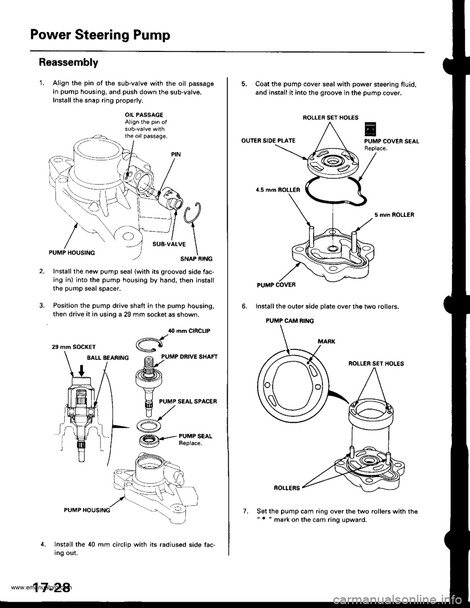
'1.Align the pin of the sub-valve with the oil passage
in pump housing, and push down the sub-valve.
Install the snsp ring properly.
OIL PASSAG€Align the pin of
the oil passage.
#q
;1..*
\SNAP RINGPUMP HOUSING
Install the new pump seal (with its grooved side fac-
ing in) into the pump housing by hand, then install
the pump seal spacer.
Position the pump drive shaft in the pump housing,
then drive it in using a 29 mm socket as shown,
BALL BEARfNG grlu,e un.t
/ /ffi\
1 / t\v4
t/ Y
# I F
PUMP SEALSPAC,ER
ry^
i- d
,O mm CIRCLIP
Hgo
/= PUMP DRIVE SHAFT
@.--#$i":*'
4,
PUMP HOUSING
Install the 40 mm circlip with its radiused side fac-
Ing out.
29 mm SOCKET
17 -2A
7.
5. Coat the pump cover seal with power steering fluid,
and install it into the groove in the pump cover.
OUTER SIDE PLATE
5 mrh ROLLER
lnstall the oute. side plate over the two rollers.
PUMP CAM RING
ROLLER SET HOLES
ROLLERS
Set the pump cam ring over the two rollers with the"' " mark on the cam ring upward.
ROLLER SET HOLES
PUMP COVER
www.emanualpro.com