cam HONDA CR-V 1998 RD1-RD3 / 1.G Owner's Guide
[x] Cancel search | Manufacturer: HONDA, Model Year: 1998, Model line: CR-V, Model: HONDA CR-V 1998 RD1-RD3 / 1.GPages: 1395, PDF Size: 35.62 MB
Page 899 of 1395
Suspension
Special Tools ............. 18-2
Component Locations
lndex ................ ...... 18-3
Wheel Alignment
Service lnformation ......................,.. 18-4
Camber .................. 18-4
Caster ............... ...... 18-5
Front Toe Inspection/
Adiustment ........ 18-5
Rear Toe Inspection/
Adiustment ........ 18-6
Turning Angle Inspection/
Adiustment ........ 18-6
Wheel/Hub Inspection
Bearing End Play .......................,...... 18-7
Wheel Runout ....... 18-7
Front Suspension
Suspension Arms Replacement ..... 18-8
Knuckle/Hub Replacement ............. 18-9
Lower Ball Joint Replacement ....... 18-15
Ball Joint Boot Replacement .......... 18-16
Front Damper
Removal ................. 18-16
Disassembly/lnspection .................. 18-1 7
Reassembly ........... 18-18
lnstallation ............. 18-18
Rear Suspension
Suspension Arms Replacement ..... 18-19
Hub Bearing Unit Replacement ...... 18-20
Upper Arm Bushing
Replacement ..... 18-23
Rear Damper
Removal ................. 18-23
Disassembly/1nspection .................. 18-24
Reassembly ........... 18-25
lnstallation ............. 18-25
www.emanualpro.com
Page 902 of 1395
Wheel Alignment
Caster
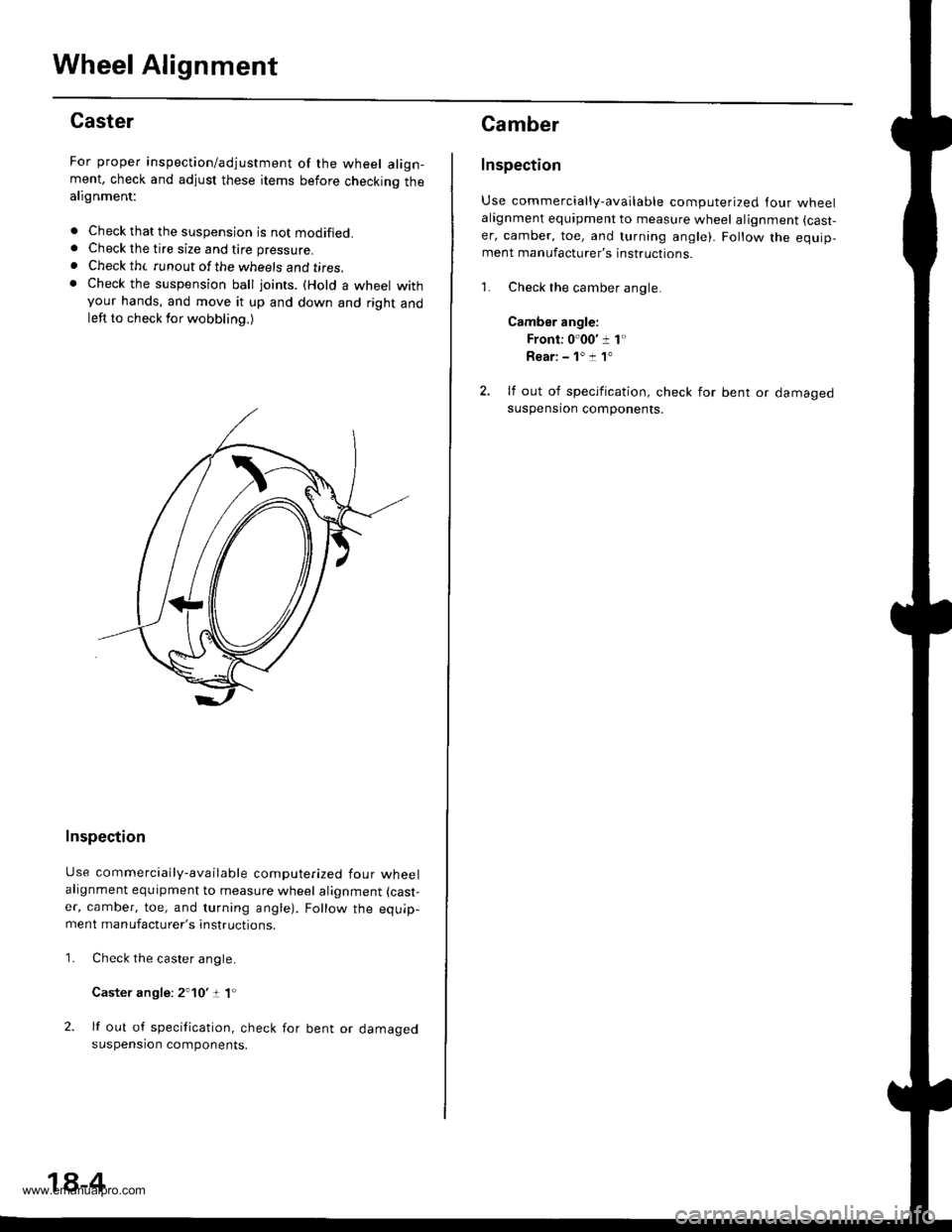
For proper inspection/adjustment of the wheel align-ment, check and adjust these items before checkinq thealignment:
. Check that the suspension is not modified.. Check the tire size and tire pressure.
. Check th( runout of the wheels and t;res,. Check the suspension ball joints. (Hold a wheel withyour hands, and move it up and down and right andleft to check for wobbling.)
Inspection
Use commercially-available computerized four wheelalignment equipment to measure wheel alignment (cast-
er, camber, toe, and turning angle). Follow the equip-ment manufacturer's instructions.
Check the caster angle.
Caster angle: 2'10':t 1"
lf out of specification, check for bent or damagedsuspension components.
1.
18-4
Camber
Inspection
Use commercially-available computerized lour wheelalagnment equipment to measure wheel alignment (cast,
er, camber, toe, and turning angle). Follow the equip,ment manufacturer's instructions.
1. Check the camber angle.
Camber angle:
Front: 0'00' 1 1"
Rear: - 1' :! 1"
2. lf out of specification, check for bent or damagedsuspensron components.
www.emanualpro.com
Page 903 of 1395
Front Toe Inspection/Adjustment
Use commercially-available computerized four wheel
alignment equipment to measure wheel alignment (caster,
camber, toe, and turning angle). Follow the equipment
manufacturer's instructions,
3.
1.Check the tire pressure.
Center the steering wheel spokes.
Check the toe with the wheels pointed straight
ahead.
Front toe-in: 0 i 3 mm {0 t 1/8 inl
- lf adjustment is required, go on to step 4.
- lf no adjustment is required, remove alignment
equipment.
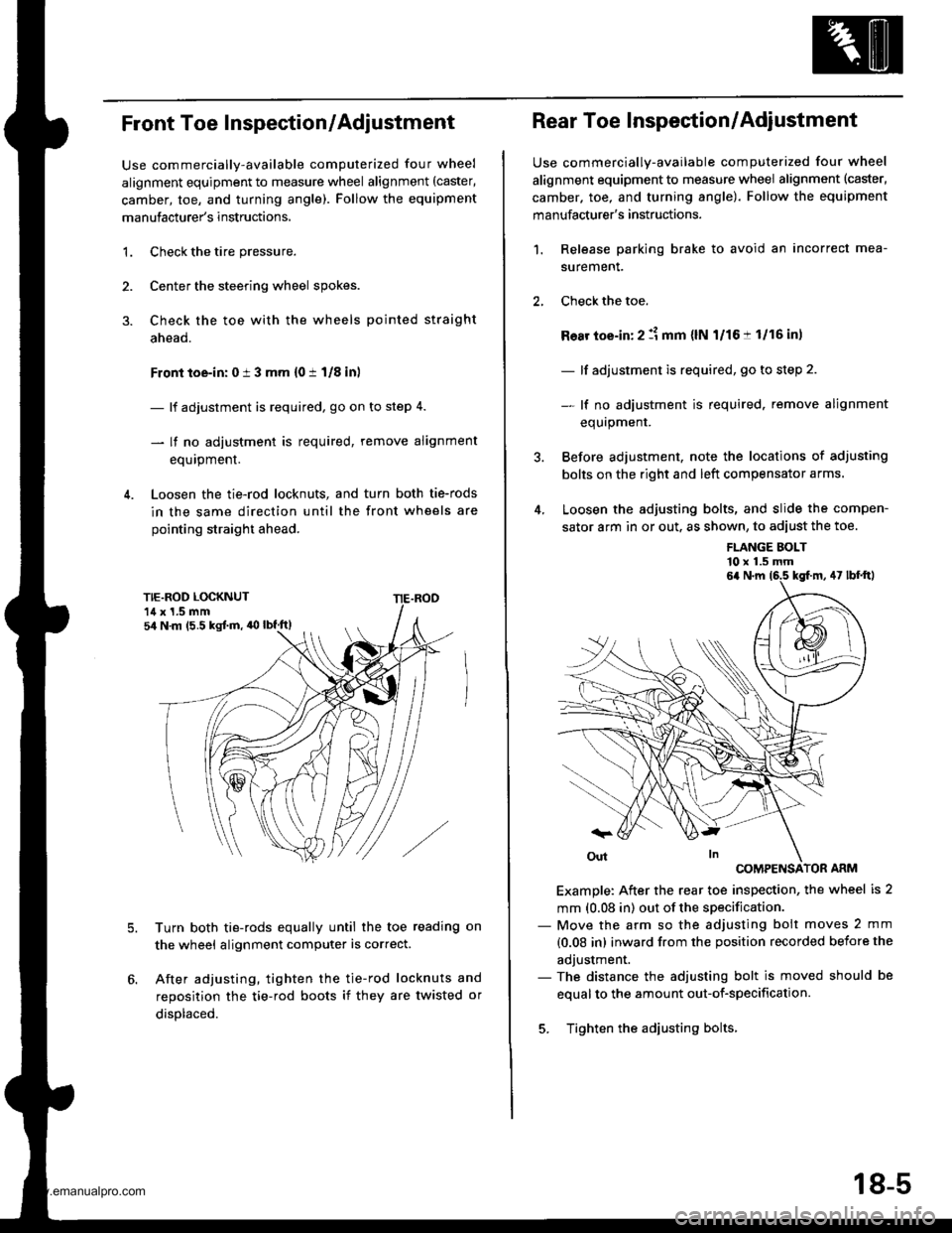
Loosen the tie-rod locknuts, and turn both tie-rods
in the same direction until the front wheels are
pointing straight ahead.
5.Turn both tie-rods equally until the toe reading on
the wheel alignment computer is correct.
After adjusting, tighten the tie-rod locknuts and
reposition the tie-rod boots if they are twisted or
displaced.
sir N m (5.5 kgJ.m, 'O lbf.ft)
Rear Toe Inspection/Adjustment
Use commercially-available computerized four wheel
alignment equipment to measure wheel alignment (caster,
camber. toe, and turning angle). Follow the equipment
manufacturer's instructions.
Release parking brake to avoid an incorrect mea-
surement.
Check the toe.
Ro8r toe-in: 2 :1 mm {lN l/16:t 1/16 in,
- lf adjustment is required, go to step 2.
- lf no adiustment is required. remove alignment
equrpmenr.
Before adjustment, note the locations of adjusting
bolts on the right and left compensator arms.
Loosen the adjusting bolts, and slide the compen-
sator arm in or out. as shown, to adiust the toe.
1.
FLANGE BOLT'10 x 1.5 mm
COMPENSATOR ARM
Example: After the rear toe inspection, the wheel is 2
mm (0.08 in) out of the specification.- Move the arm so the adjusting bolt moves 2 mm
{0.08 in) inward from the position recorded before the
adjustment.- The distance the adjusting bolt is moved should be
equal to the amount out-of-specification.
5. Tighten the adjusting bolts.
6a N.m 16.5 kgf.m, 47 lbf'ftl
18-5
www.emanualpro.com
Page 904 of 1395
Wheel Alignment
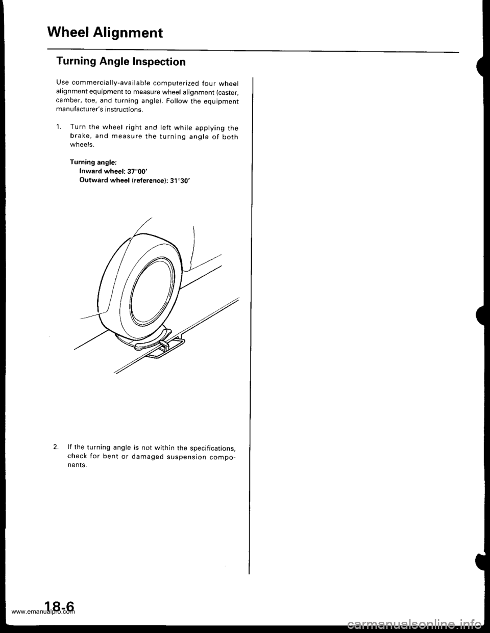
Turning Angle Inspection
Use commercially-available computerized four wheelalignment equipment to measure wheel alignment (caster,
camber, toe, and turning angle). Follow the equipmentmanufacturer's instructions.
1. Turn the wheel right and left while applying thebrake, and measure the turning angle of bothwneets.
Turning angle:
Inward wheel: 37.00'
Outward wheel lreference): 31.30'
2.lf the turning angle
check for be nt or
nenIs.
is not within the specifications,
damaged suspension compo-
18-6
www.emanualpro.com
Page 1019 of 1395
Glass
Ouarter Glass Replacement (cont'd)
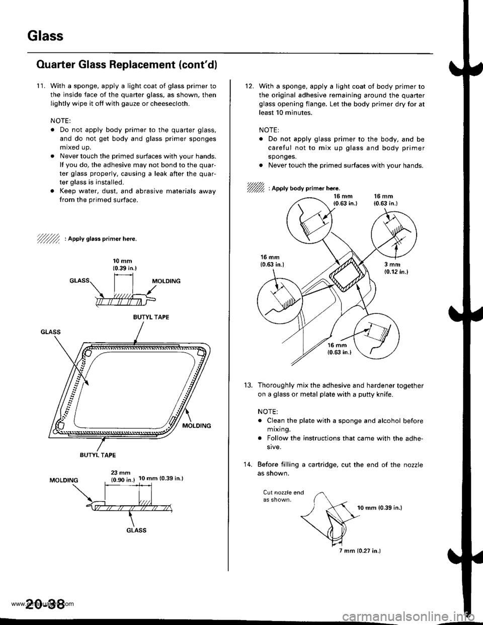
1 1. With a sponge, apply a light coat of glass primer to
the inside face of the quaner glass, as shown, then
lightly wipe it off with gauze or cheesecloth.
NOTE:
. Do not apply body primer to the quarter glass,
and do not get body and glass primer sponges
mrxed up.
. Never touch the primed surfaces with your hands.
It you do, the adhesive may not bond to the quar-
ter glass properly. causing a leak after the quar
ter glass is installed.
. Keep water, dust, and abrasive materials away
from the primed surface.
7///f ' aeery sra$ primer here.
10 mm{0.39 in.)
BUTYL TAPE
BUTYL TAPE
MOLOING23 mm10.90 in.)10 mm 10.39 in.)
GLASS
20-38
With a sponge, apply a light coat of body primer to
the original adhesive remaining around the quaner
glass opening flange. Let the body primer dry for at
least 10 minutes.
NOTE:
. Do not apply glass primer to the body, and be
careful not to mix up glass and body primer
sponges.
. Never touch the primed surfaces with your hands.
'/fu, : Apply body primer here.
'13.Thoroughly mix the adhesive and hardener together
on a glass or metal plate with a putty knife.
NOTE:
. Clean the plate with a sponge and alcohol before
m ixing.
. Follow the instructions that came with the adhe-
slve.
Before filling a cartridge, cut the end of the nozzle
as snown.
Cut nozzle end
10 mm {0.39 in.)
7 mm {0.27 in.)
14.
www.emanualpro.com
Page 1392 of 1395
SRS Unit
).0Replacement
CAUTION:
. Before disconnecting any part of the SRS wire har-
nesg, disconnect the airbag connoctors (and soat beh
tensioner connectorsl.
. During installation or replacament, do not bump(impact wrench, hammer etc.) the area near the SRS
unit.
Do not damage the SFS unit terminalg or connsc-
lors.
Do not disassemble the SRS unit it has no saryice-
able parts,
Store the SRS unit in a clean, dry area.
Do not use any SRS unit which has been subiected
to water damage or shows signs ot being dropped orimproperly handlgd, such as dents, cracks or defor-
mation.
Disconnect the battery negative cable, then discon-
nect the positive cable from the battery, andwaitat
least three minutes.
Disconnect the airbag connectors (and seat belt ten-
sioner connectors). (When disconnected, the airbag
and seat belt tensioner connectors are automatical-
ly shorted.)
Driver's Side:
. Remove the access panel from the steering
wheel, then disconnect the 2P connector
between the driver's airbag and cable reel (see
page 24-231.
Front Passenger's Side:. Disconnect the 2P connector between the frontpassenger's airbag and SRS main harness (see
page 24-231.
Soat Beh Tensionor ('98 - 00 modelsr:. Remove the left and right center pillar lower trimpanels (see section 20).
. Disconnect the seat belt tensioner 2P connectors
from the left side wire harness (driver's side) and
the right wire harness (front passenger's side)(see page 24'231.
2.
a
a
'1.
)
)o
24-95
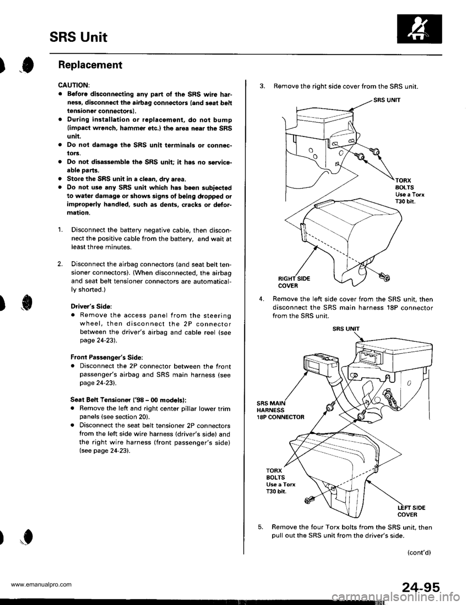
3. Remove the right side cover from the SRS unit.
SRS UNIT
TORXAOLTSUse a TorxT30 bir.
COVER
Remove the left slde cover from the SRS unit. then
disconnect the SRS main harness 18P connector
from the SRS unit.
sRsHARNESS18P CONNECTOR
TORXBOLTSUs€ a TorxT30 bir.
stoECOVER
Remove the four Torx bolts from the SRS unit. then
oull out the SRS unit from the driver's side.
(cont'd)
www.emanualpro.com
Page 1395 of 1395
Airbag/Seat Belt Tensioner
1.
Disposal (cont'dl
Connect a 12 volt battery to the tool'
. It the green light on the tool comes on, the air-
bag igniter circuit is defective and cannot deploy
the airbag. Go to Damaged Airbag Special
Procedure.
.lftheredlightonthetool comes on, the airbag is
ready to be deployed.
Push the tool's deployment switch. The airbag
should deploy (deployment is both highly audible
and visible; a loud noise and rapid inflation of the
bag, followed by slow deflation).
. lf the airbags deploy and the green light on the
tool comes on, continue with this procedure.
. lf an airbag doesn't deploy, yet the green light
comes ON, its igniter is defective. Go to Dam-
aged Airbag Special Procedure.
. During deployment, the airbag can become hot
enough to burn you, Wait thirty minutes after
deployment before touching the airbag.
Dispose of the complete airbag. No part of it can be
reused. Place it in a sturdy plastic bag, and seal it
securety.
CAUTION:
. Wear a faco shield and gloves when handling a
deployed airbag.
. Wash your hands and rinse them well with
water after handling a deployed airbag.
24-98
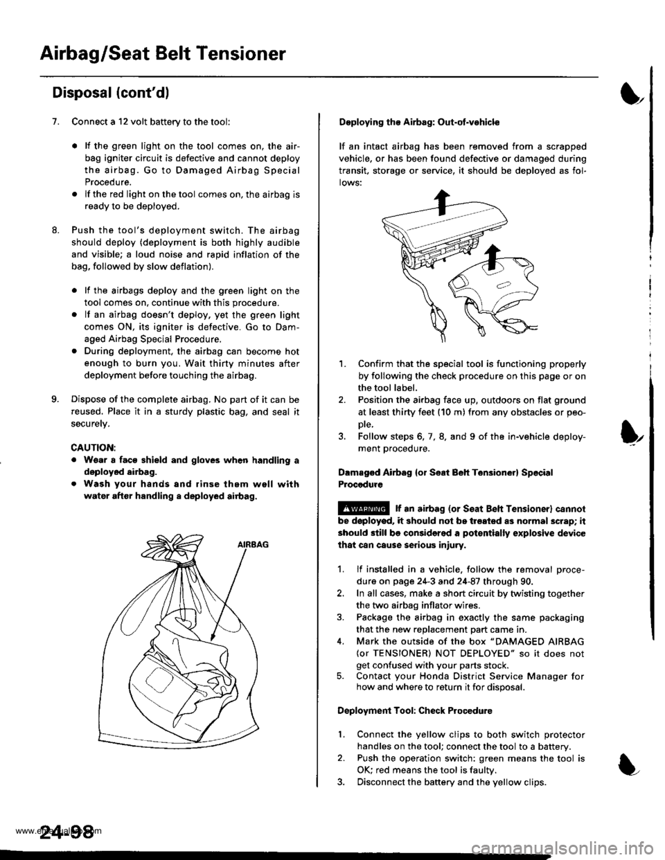
Deploying tho Airbag: Out-ot.vohicle
lf an intact airbag has been removed from a scrapped
vehicle, or has been found defective or damagsd during
transit. storage or seryice, it should be deployed as fol-
lows:
'L Confirm that the special tool is functioning properly
by following the check procedure on this page or on
the tool label.
2. Position the airbag face up, outdoors on flat ground
at least thirty feet (10 m) from any obstacles or peo-
Dte,
3. Follow steps 6, 7, 8. and 9 of the in-vehicle deploy-
ment proceoure.
Dlmaged Airbsg {or Seat Beh Ten3ion6r} Sp6cial
Procgdure
!@ r an airbag {or seat Beh rensioner} cannol
be doployod, it should not be treated as normal scrap; it
should still be considered a pot€ntially explosive device
lhat can cause serious iniury.
1. lf installed in a vehicle. follow the removal proce-
dure on page 24-3 and 24-87 through 90.
2. In all cases, make a short circuit by twisting together
the two airbag inflator wires.
3. Package the airbag in exactly the same packaging
that the new reDlacement Dart came in.
4. Mark the outside of the box "DAMAGED AIRBAG
{or TENSIONER) NOT DEPLOYED" so it does not
get confused with your parts stock.5. Contact your Honda District Service Manager forhow and where to return it for disposal.
Deployment Tool: Check Procedure
Connect the yellow clips to both switch protector
handles on the tool; connect the tool to a battery.
Push the operation switch: green means the tool is
OK: red means the tool is faultv.
Disconnect the baftery and the yellow clips.
I
t
l.
www.emanualpro.com