front end HONDA CR-V 1998 RD1-RD3 / 1.G Repair Manual
[x] Cancel search | Manufacturer: HONDA, Model Year: 1998, Model line: CR-V, Model: HONDA CR-V 1998 RD1-RD3 / 1.GPages: 1395, PDF Size: 35.62 MB
Page 1080 of 1395
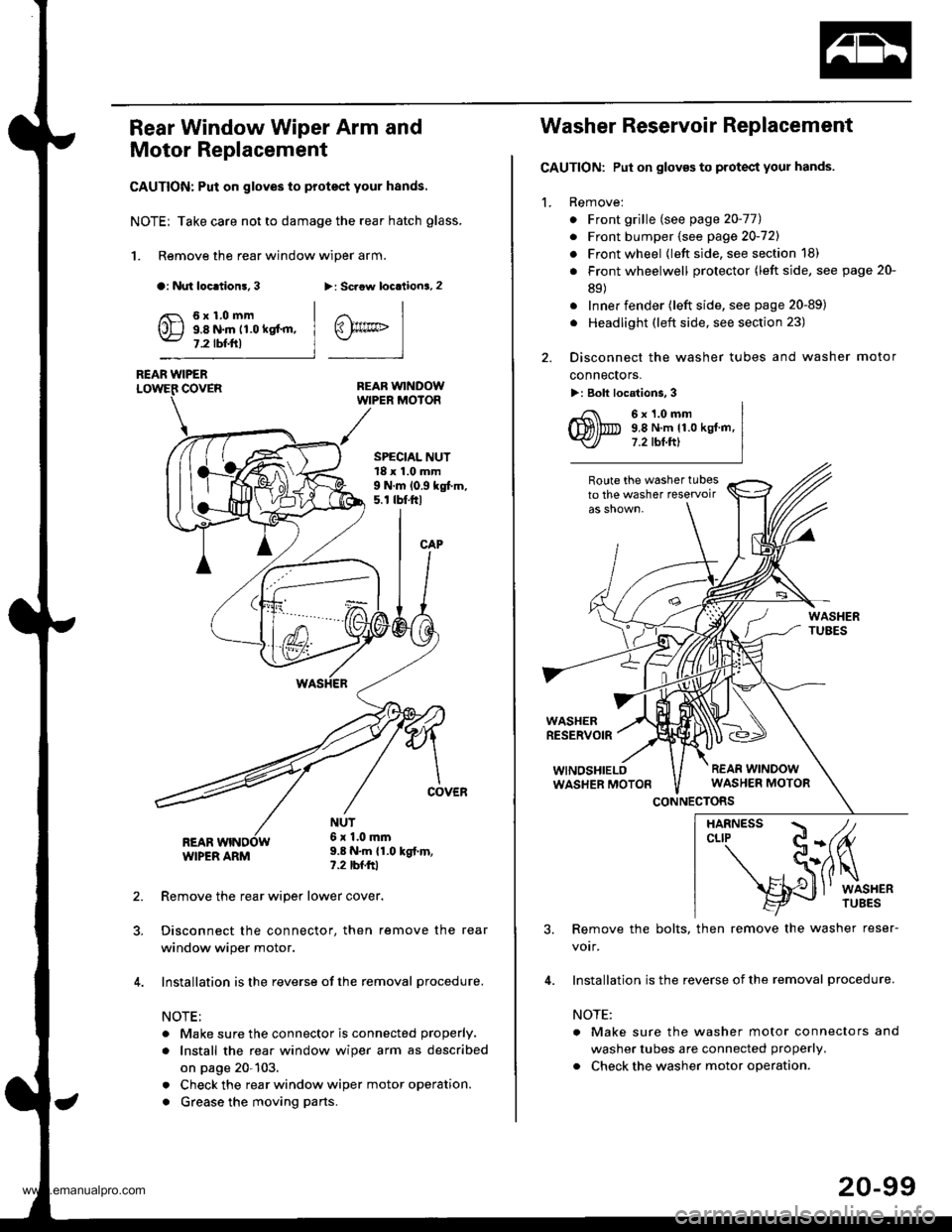
Rear Window Wiper Arm and
Motor Replacement
CAUTION: Put on gloves to protect your hands.
NOTE; Take care not to damage the rear hatch glass.
1. Remove the rear window wiper arm.
a: Nut loc.tion!, 3>: Scaow locationa, 2
REAR WINDOWWIPER MOIOR
REAR WIPERCOVER
REARWIPER ARM
6x1.0mm9.8 N.m 11.0 kgt'm,7.2 tbf.ftl
SPECIAL NUT18 x 1.0 mm9 N.m 10.9 kgt m,5. r tbt.ftl
NUT6x 1.0mm9.8 N.m {1.0 kgt.m,?.2 tbfftl
Remove the rear wiper lower cover.
Disconnect the connector, then remove the rear
window wiper motor.
Installation is the reverse of the removal procedure.
NOTE:
. Make sure the connector is connected properly.
. Install the rea. window wiper arm as described
on page 20-103.
. Check the rear window wiper motor operation.
. Grease the moving parts.
@rrc
Washer Reservoir Replacement
GAUTION: Put on gloves to protect your hands.
1. Remove:
. Front grille (see page 20-771
. Front bumper (see page 20-721
. Front wheel {left side, see section 18)
. Front wheelwell protector (left side, see page 20-
89)
. Inner fender (left side, see page 20-89)
. Headlight (left side, see section 23)
2. Disconnect the washer tubes and washer motor
connectors.
>: Bolt locations, 3
6x1.0mm9,8 N.m 11.0 kgt.m,7.2 tbt.ftl
Route the washer tubesto the washer teservoir
WASHERRESERVOIR
WINOSHIELOWASHER MOTON
CONNECTORS
3. Remove the bolts, then remove the washer reser-
votr,
4. Installation is the reverse of the removal procedure.
NOTE:
a Make sure the washer motor connectors and
washer tubes are connected properly.
. Check the washer motor operation.
HARNESS / tcLrP C-(fu
- S(ilq
s{J
l' wrsHER
20-99
www.emanualpro.com
Page 1081 of 1395
Wiper/Washer
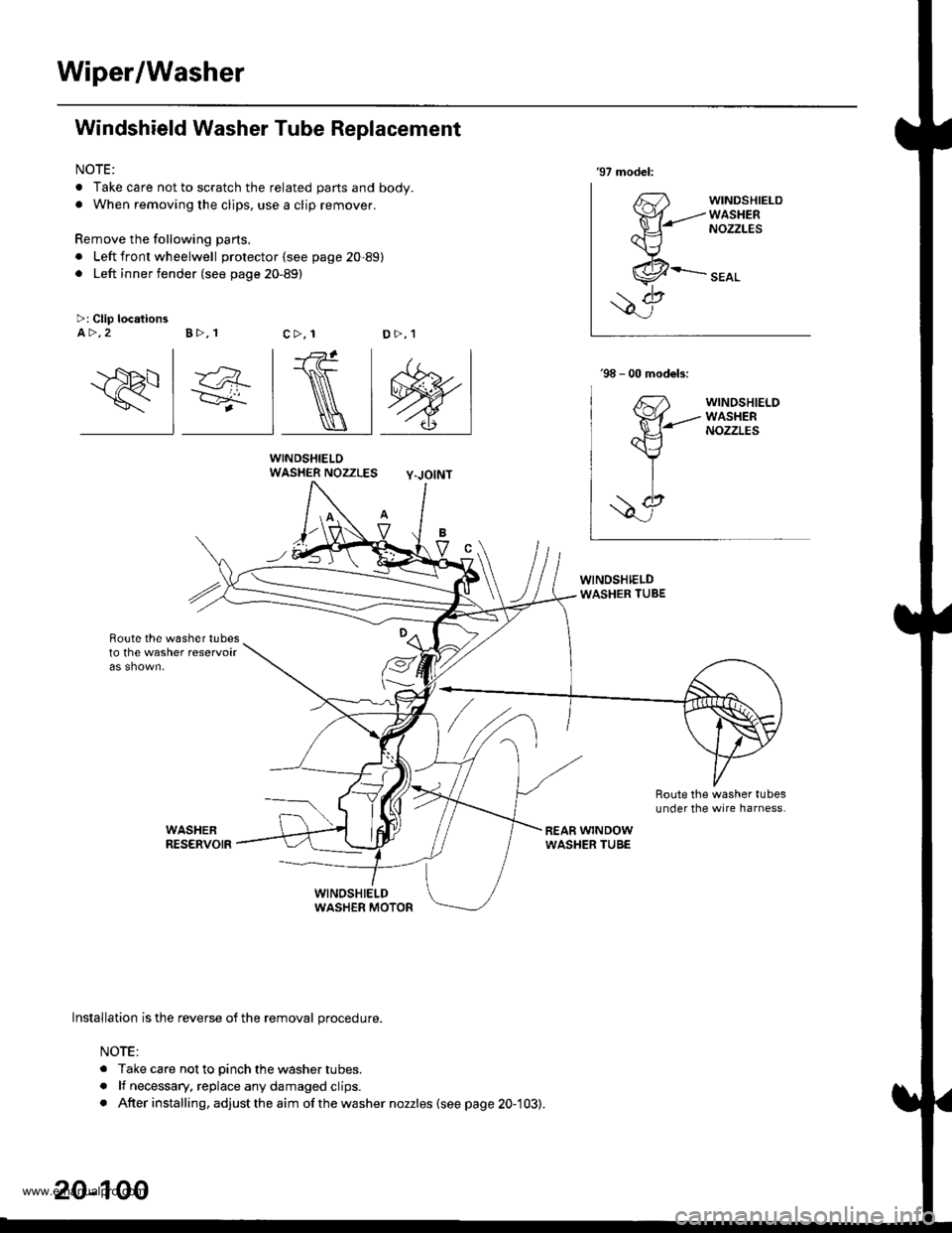
Windshield Washer Tube Replacement
NOTE:
. Take care not to scratch the related parts and body.. When removing the clips, use a clip remover.
Remove the following parts.
. Left front wheelwell protector (see page 20-89). Left inner fender (see page 20-89)
WINDSHIELOWASHER NOZZLES Y-JOINT
Boute the w6sher tubesto the washer reservoir
'97 model:
63'fr{-------
ax---\J
,.&--
\7>: Clip locationsA >,2 B >,1c>, 1D>,1
\
lnstallation is the reverse of the removal procedure.
NOTE:
. Take care not to pinch the washer tubes.
. lf necessary, replace any damaged clips.. After installing, adjust the aim ofthe washer nozzles (see page 20-103).
20-100
www.emanualpro.com
Page 1082 of 1395
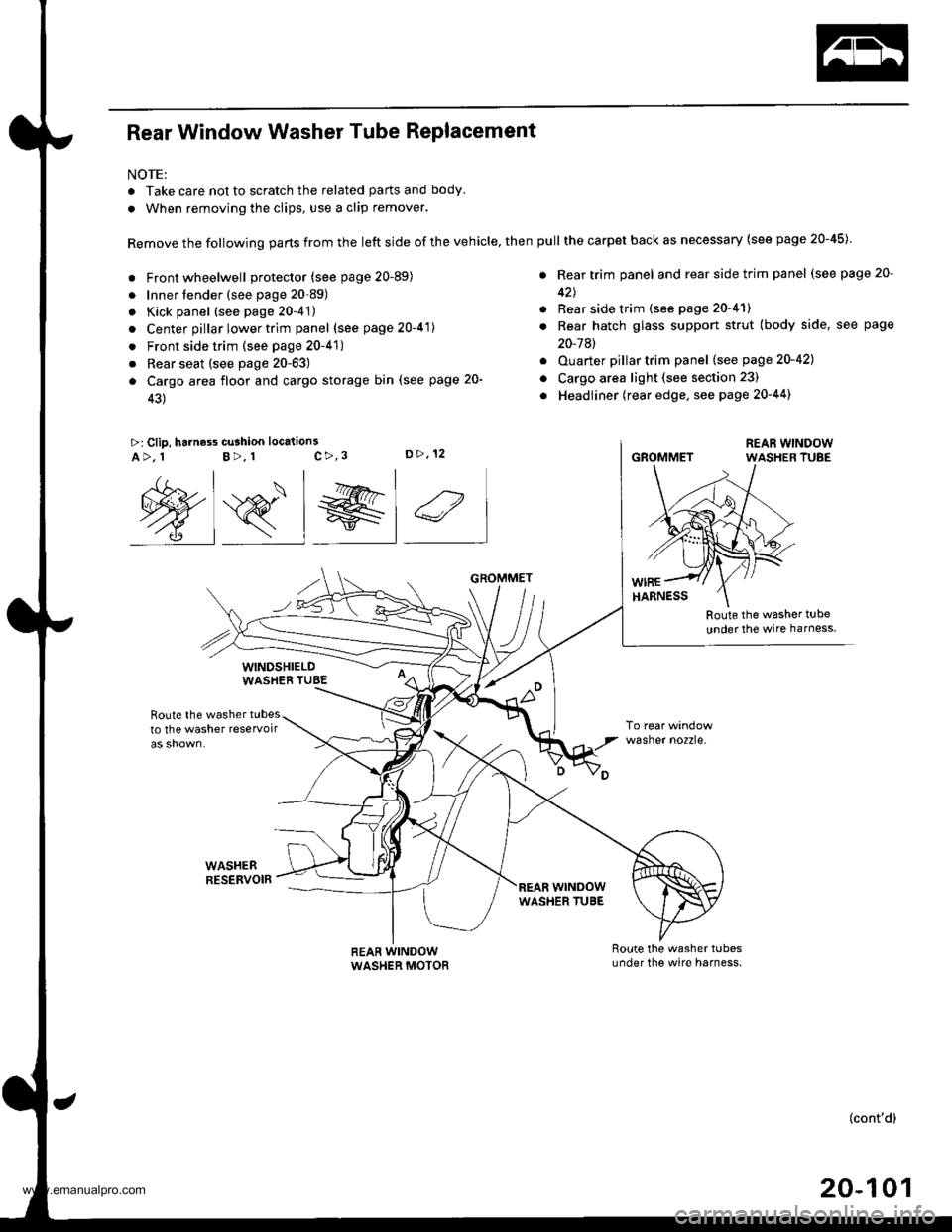
Rear Window Washer Tube Replacement
NOTE:
. Take care not to scratch the related parts and body.
. When removing the clips, use a clip remover.
Remove the following parts from the left side of the vehicle, then
. Front wheelwell protector (see page 20-89)
. Innertender (see page 20-89)
. Kick panel (see page 20-4't)
. Center pillar lower trim panel (see page 20-41)
. Front side trim (see page 20-41)
. Rear seat (see page 20-63)
a Cargo area floor and cargo storage bin (see page 20-
43)
>: Clip, harness cu3hion location3c>,3D>,12A>, 1B>, 1
Route the washer t!be
under the wire harness
Route the washer tubesto the washer reservoir
WASHEBRESERVOIR
wasner no2zre.
@s_l el 4
WINDSHIELDWASHEB TUBE
REAR WINDOWWASHER MOTOR
GROMMET
wrNoowWASHER TUBE
pull the carpet back as necessary (see page 20-45)
. Rear trim panel and rear side trim panel (see page 20-
42J
. Rear side trim (see page 20-41)
. Rear hatch glass support strut (body side, see page
20-7Al
. Ouarter pillartrim panel (see page 20-421
o Cargo area light (see section 23)
. Headliner (rear edge, see page 20-44)
GROMMET
(cont'd)
20-101
www.emanualpro.com
Page 1090 of 1395
a
Heater and Air Conditioning
Heater ...........21
NOTE: Section 21 ("Heater") is included in section 22.
Air Conditioning ......'..'.. '.'22'1
SUPPLEMENTAL RESTRAINT SYSTEM (SRS}
This model has an SRS which includes a driver's airbag in the steering wheel hub, a passenger's airbag in the dashboard
above the glove box ('97,00 models). and seat belt tensioners in the seat belt retractors ('98 - 00 models). Information
necessary to safely service the SRS is included in this Service Manual. ltems marked with an asterisk (*) on the contents
page include. or are located near, SRS components. Servicing, disassembling or replacing these items will require special
precautions and tools, and should only be done by an authorized Honda dealer.
@. To avoid rendering the SRS inoperative, which could lead to personal iniury or death in the event of 8 severe frontal
collision, all SRS service work must be performed by an authotized Honda dealer.
lmproper service procedures, including incorrect removal and installation of the SRS, could lead to personal iniury
caused by unintentional deployment of the airbags ('97 - 00 models), and seat belt tensioners 138 - 00 models).
Do not bump the SRS unit. Otherwise, the system may fail in case of a collision, or the airbags may deploy when the
ignition switch is ON {lll.
SRS eleqtrical wiring harnesses are identified by yellow color coding. Related components are located in the steering
column, front console, dashboard, dashboard lower panel, and in the dashboard above the glove box. Do not use elec-
tricaltest equipment on thes€ cilcuils.
www.emanualpro.com
Page 1241 of 1395
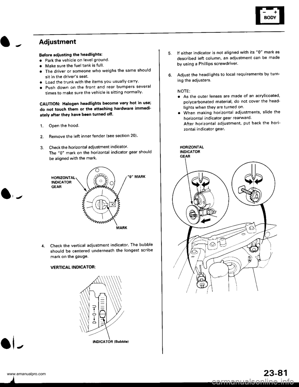
Adjustment
Bstore adiusting the headlights:
. Park the vehicle on level ground
. Make sure the fuel tank is tull
. The driver or someone who weighs the same should
sit in the driver's seat.
. Load the trunk with the items you usually carry'
. Push down on the front and rear bumpers several
times to make sure the vehicle is sitting normally'
CAUTION: Halogen headlights become very hot in use;
do not touch them or the atiaching hardware immedi-
ately after they have been turned off.
1. ODen the hood.
2. Remove the left inner fender {see section 20).
3. Checkthe horizontal adjustment indicator.
The "0" mark on the horizontal indicator gear should
be aligned with the mark.
"0" MARK
Check the vertical adjustment indicator. The bubble
should be centered underneath the longest scribe
mark on the gauge.
VERTICAL INDICATOR:
ol-
)
5.lf either indicator is not aligned with its "0" mark as
described left column, an adjustment can be made
by using a Phillips screwdriver.
Adjust the headlights to local requirements by turn-
ing the adjusters.
NOTE:
. As the outer lenses are made of an acrylicoated,
polycarbonated material, do not cover the head-
lights when they are turned on
. When making horizontal adiustments, slide the
horizontal indicator gear rearward.
After horizontal adjustment, put back the hori-
zontal indicator gear.
HORIZONTALINDICATORGEAR
23-A1
www.emanualpro.com
Page 1314 of 1395
Description
J)
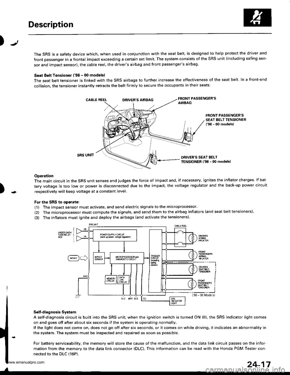
The SRS is a safety device which, when used in conjunction with the seat belt, is designed to help protect the driver and
front passenger in a frontal impact exceeding a certain set limit. The system consists of the SRS unit (including safing sen-
sor and impact sensor), the cable reel, the driver's airbag and front passenger's airbag.
Seat Bolt Tensioner {'98 - 00 models}
The seat belt tensioner is linked with the SRS airbags to further increase the effectiveness of the seat belt. In a front-end
collision, the tensioner instantly retracts the belt firmly to secure the occupants in their seats
FRONT PASSENGER'SAIREAGDRIVER'S AIRBAG
FRONT PASSENGER'SSEAT BELT TENSIONER{'98 - 00 modelsl
)
SRS UNITDRIVER'S SEAT BELTTENSIONER l'98 - 0O modeb)
Operation
The main circuit in the SRS unit senses and judges the force of impact and, if necessary, ignites the intlator charges. lf bat
tery voltage is too low or power is disconnected due to the impact, the voltage regulator and the back-up power circuit
respectively will keep voltage at a constant level.
For the SRS to operate:
(1) The impact sensor must activate, and send electric signals to the microprocessor.
(2) The microprocessor must compute the signals, and send them to the airbag inflators (and seat belt tensioners).
(3) The inflators must ignite and deploy the airbags (and activate the tensioners).
Selt-diagnosis System
A self-diagnosis circuit is built into the SRS uniU when the ignition switch is turned ON (ll), the SRS indicator Iight comes
on and goes off after about six seconds if the system is operating normally.
lf the light does not come on, does not go off after six seconds, or it comes on while driving, it indicates an abnormality in
the system. The system must be inspected and repaired as soon as possible.
For battery serviceability, the memory will store the cause of the malfunction, and the data link circuit passes on the infor
mation from the memory to the data link connector (DLC). This information can be read with the Honda PGM Tester con-
nected to the DLC {16P).
198
---__-l
TENSTO1En II
_-___J- 00 N4ode s)
24-17
www.emanualpro.com
Page 1339 of 1395
Troubleshooting
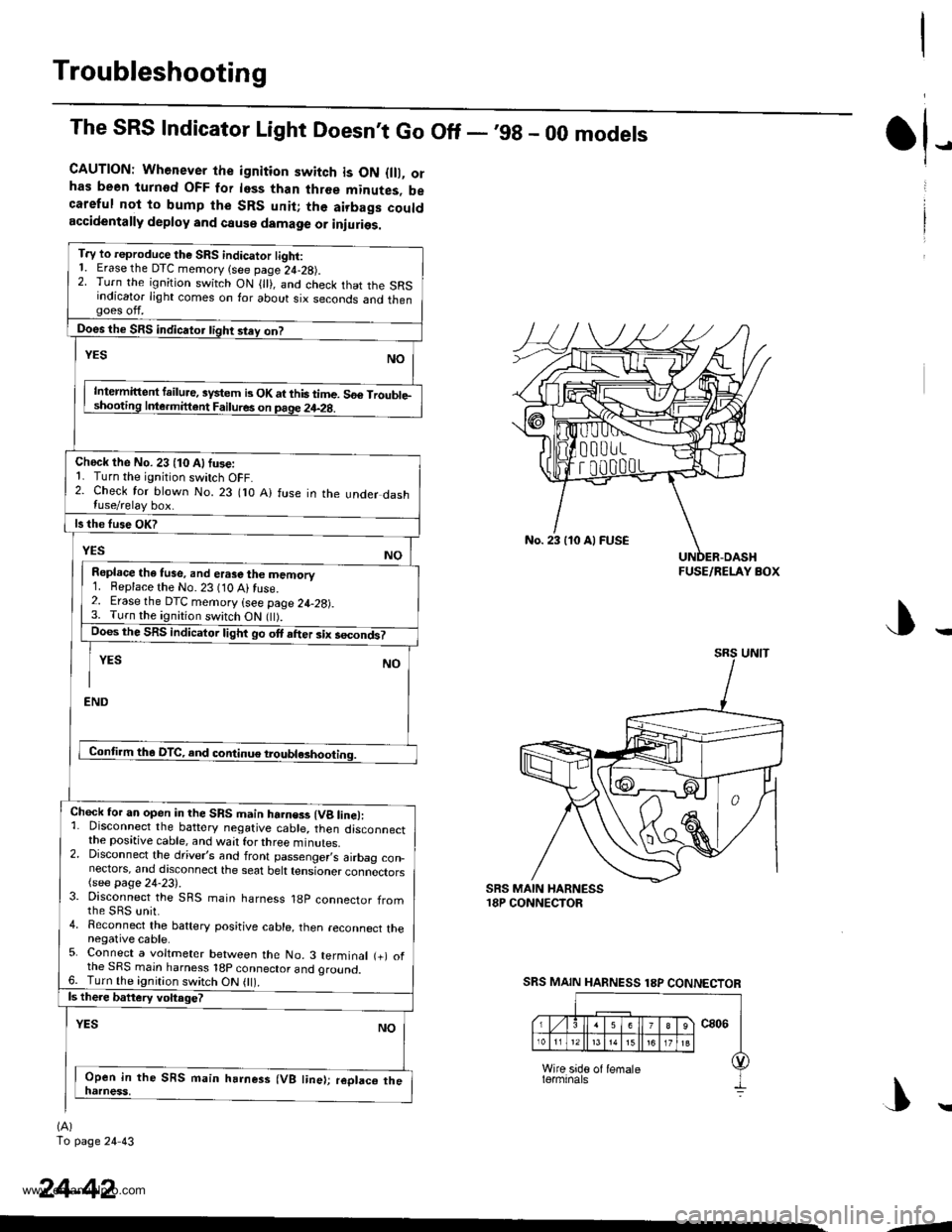
The SRS Indicator Light Doesnt Go Off - ,99 - 00 models
CAUTION: Whenever the ignition switch is ON {lll, orhas been turnod OFF for less than three minutes, becareful not to bump the SRS unit; the airbags couldaccidentally deploy and cause damage or iniuries.
T.y to reproduce the SRS indicator tight:1. Erase the DTC memory (see page 24-28).2. Turn the ignition switch ON { }, and check that the SRSindicator light comes on for about six seconds and thengoes off.
Does the SRS indicator tight stey on?
NOYES
Intermittent failure, system b OK at this time. 56€ Trouble-shooting Inle.mittent Failures on page 24-2g.
Check the No. 23 (10 Alfuse:1. Turn the ignition switch OFF.2. Check for blown No. 23 flO A) fuse in the under dashluse/relay box.
ls the fuse OK?
YESNO
Repl.ce the tuse, and erase the memory1. Beplace the No. 23 (10 Ai fuse.2. Erase the DTC memory (see page 24-28).3. Turn the ignition switch ON flt).Does the SRS indicator light go ott after six secondt
YES NO
I
END
Conti.m tha DTC, and continue troubl*hooting.
Chock for an open in the SRS main harness (Vg line):1. Disconnect the battery negative cable, then disconnectthe positive cable, and wait for three minutes.2. Disconnect the driver,s and front passenger,s airbag con_nectors, and discoonect the seat belt tensioner connectors(see page 24-23).3. Disconnect the SRS main harness 18p connector fromthe sRs unit.4. Reconnect the baftery positive cable, then reconnect thenegative cable.5. Connect a voltmeter between the No. 3 terminal (+) ofthe SRS main harness 18p connector and oround.6. Turn the ignition switch ON 0l).ls there battery voltage?
YESNO
Open in the SRS main harness (VB line); replaco thenatness,
(A)
To page 24 43
tl-
24-42
No. 23 110 Al FUSE
FUSE/RELAY BOX
SRS MAIN HARNESS 18P CONNECTOR
|\
-1
www.emanualpro.com
Page 1394 of 1395
Airbag/Seat Belt Tensioner
)Disposal
)
Before scrapping any airbags {and seat belt tansioners)
(including those in a whole vehicle to be scrappedl. the
airbags (and seat belt tensioners) must be deployed. lf
the vehicle is still within the warrantv oeriod the Honda
District Service Manager must give approval and/or spe-
cial instructions, before you deploy the airbags (and seat
belt tensioners). Only after the airbags {and seat belt ten-
sioners) have been deployed (as the result of vehicle col-
lision, for example), can they be scrapped.
lf the airbags (and seat belt tensioners) appear intact
(not deployed), treat them with extreme caution.
Follow this procedure:
Doploying tho Airbags (and Soat B6li Ten3ione6):
ln-vehicle
lf an SRS vehicle is to be entirely scrapped, its airbags(and seat belt tensioners) should be deployed while still
in the vehicle. The airbags (and seat belt tensioners)
should not be considered as salvageable parts and
should never be installed in another vehicle.
@ confirm that each airbag {and seat belt
tonsiongr) i3 ggcurely mountod; othgrwise, severe per-
sonal iniury could result from d6ploym6nt,
1. Disconnect the battery negative cable, then discon-
nect the oositive cable.
Confirm that the special tool is functioning properly
by following the check procedure on the tool label
or on page 24-98.
Remove the access panel, then disconnect the 2P
connector between the driver's airbag and the cable
reel (see page 24-23).
Remove the glove box, then disconnect the 2P con-
nector between the front passenger's airbag and
SRS main harness (see page 24-23).
Remove the center pillar lower trim panel, then dis-
connect the 2P connector between the seat belt ten-
sioner and side wire harness ('98 - 00 models) (see
page 24-231.
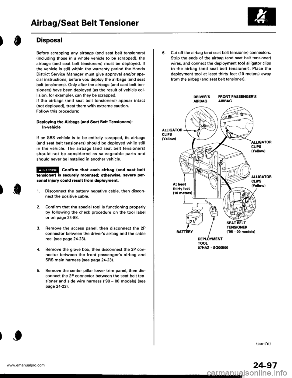
6. Cut off the airbag (and seat belt tensioner) connectors.
Strip the ends of the airbag (and seat belt tensioner)
wires. and connect the deployment tool alligator clips
to the airbag (and seat belt tensioner). Place the
deployment tool at least thirty feet (10 meters) away
from the airbao (and seat belt tensioner),
DRIVER'S FRONTPASSENGER'SAIBBAG AIRBAG
AI.IIGATORcuPslY6llowl
At lcastthirty feot
110 motersl
(cont'd)
24-97
www.emanualpro.com