sensor system HONDA CR-V 1998 RD1-RD3 / 1.G Manual PDF
[x] Cancel search | Manufacturer: HONDA, Model Year: 1998, Model line: CR-V, Model: HONDA CR-V 1998 RD1-RD3 / 1.GPages: 1395, PDF Size: 35.62 MB
Page 531 of 1395
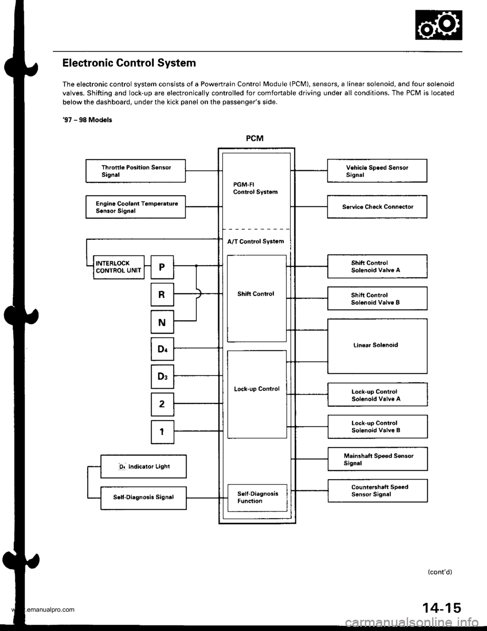
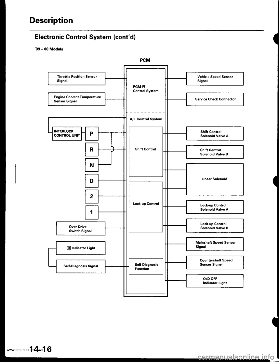
Electronic Control System
The electronic control svstem consists of a Powertrain Control Module (PCM), sensors, a linear solenoid, and four solenoid
valves. Shifting and lock-up are electronically controlled for comfortable driving under all conditions. The PCM is located
below the dashboard, under the kick panel on the passenger's side.
'97 - 98 Mod€ls
PGM.FIControl Sy3t6m
Throttl€ Poshion SensorSignalVehicle Sp.ed SensorSignal
Engino Coolant TamperetureService Check connectorSonsor Signrl
A/T Control Sy3tem
INTERLOCK
Shift Cont.ol
Shift ControlSolenoid valve ACONTROL UNITr
RShift ControlSolenoid Valve B
N
Linear SolenoidDr
Lock-up Control
Ds
Lock-up ControlSolenoid Valve A2
Lock-up ConirolSol6noid valvo B1
M.inshaft Spoed SensorSignel-D! Indicator Light
Count€rahaft Speedsensor SignelSelt-Oiagnosb signel
I
Sell-DiagnosisFunction
l-
{cont'd)
14-15
www.emanualpro.com
Page 532 of 1395
Description
PCM
PGM.FIControl System
Throttle Position SensorSignelVehicle Speed SensorSignal
Engin€ Coolsnt TomperatureSen30r SignalService Ch€ck Connectol
A/T Control Svstem
INTERLOCK
Shift Control
Shift ConlrolSolenoid Valve ACONTROL UNITr
RShift ControlSolenoid Valve B
N
Linear SolenoidD
Lock-up Control
2
Lock-up ControlSolenoid valve A1
Lock-up ControlSolenoid Valve BOver-DriveSwitch Signal
Mainshaft Speed SensorSignalE Indicator Light
Countershaft SpeedSensor SigntlSelt-Oiagnosis SigndSelf-DiagnosisFunc{ion
O/D OFFIndicetor Light
Electronic Gontrol System (cont'd)
'99 - 00 Models
14-16
www.emanualpro.com
Page 533 of 1395
Shift Control
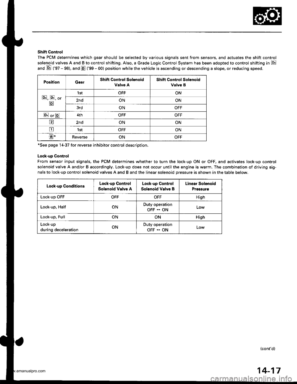
The PCM determines which gear should be selected by various signals sent from sensors, and actuates the shift control
solenoid valves A and B to control shifting. Also. a Grade Logic Control System has been adopted to control shifting in E
anO E ('gZ - gg), and E ('99 - 00) position while the vehicle is ascending or descending a slope, or reducing speeo.
PositionGearShift Control Solenoid
Valve A
Shift Control Solonoid
Valve B
E, E, Or
E
'I stOFFON
2ndONON
3rdONOFF
E orE4thOFFOFF
a2ndONON
tr1stOFFON
E-ReverseONOFF
*See page 14-37 for reverse inhibitor control description.
Lock-up Control
From sensor input signals, the PCM determines whether to turn the lock-up ON or OFF, and activates lock-up control
solenoid valve A and/or B accordingly. Lock-up does not occur until the engine is warm. The combination of driving sig-
nals to lock-up control solenoid valves A and B and the linear solenoid pressure is shown in the table below.
Lock-up ConditionsLock-up Control
Solonoid Valve A
Lock-up Control
Solenoid Valve B
Linear Solenoid
Pressuro
LOCK-Up \JrrOFFOFFHigh
Lock-up, HalfONDuty operation
OFF - ON
Lock-up, FullONONHish
Lock-up
during decelerationONDuty operation
OFF - ONLow
(cont'd)
14-17
www.emanualpro.com
Page 534 of 1395
Description
Electronic Control System (cont'dl
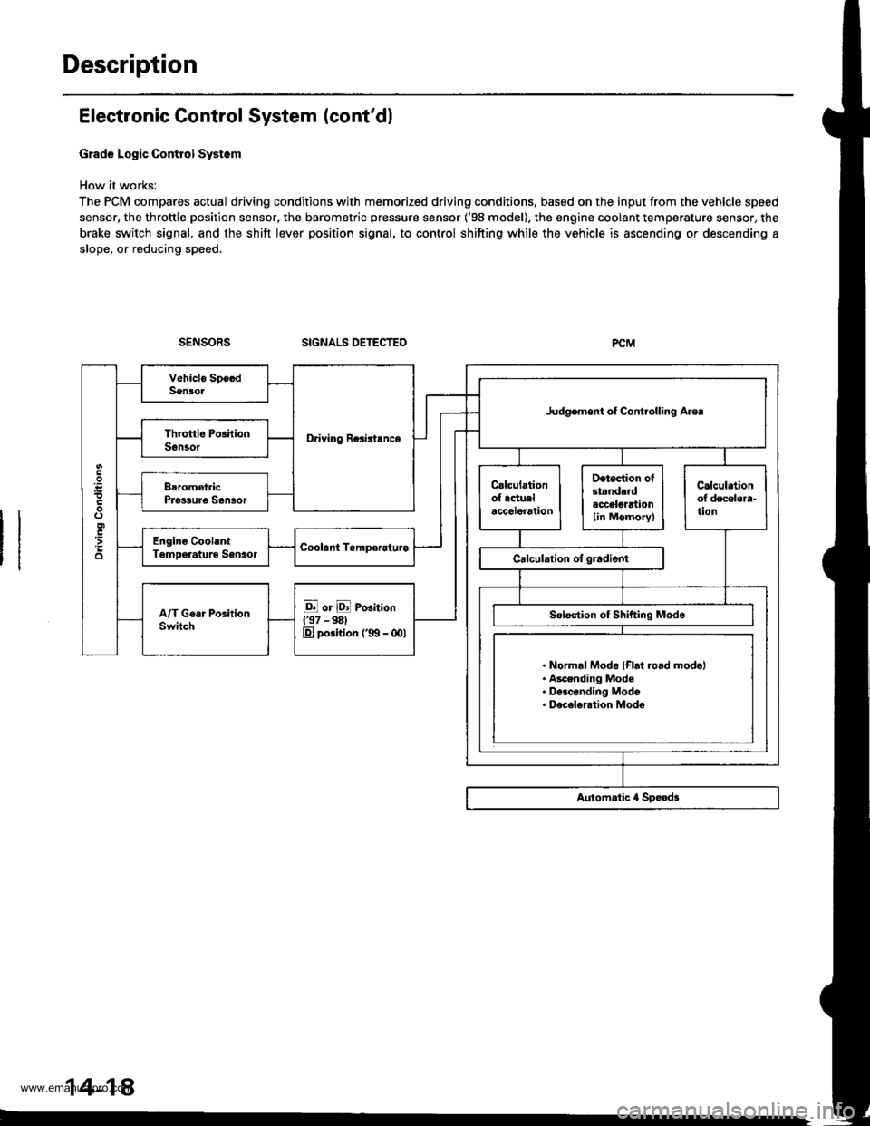
Grade Logic Control System
How it works:
The PCM compares actual driving conditions with memorized driving conditions, based on the input from the vehicle speed
sensor, the throttle position sensor, the barometric pressure sensor ('98 model). the engine coolant temperature sensor, the
brake switch signal, and the shift lever position signal, to control shifting while the vehicle is ascending or descending a
slope, or reducing speed.
SIGNALS DETECTED
Driving Rcsisl.nce
Judgemont ot Controlling Aroa
. Normal Modo {Flrt ro.d mode}. Ascending Mode. Deacending Mode. Deceleration Mode
14-14
www.emanualpro.com
Page 565 of 1395

PCM CONNECTOR B (25P) lcont'd)
PCM CONNECTOR C {31PI
PCM CONNECTOR D II6PI
Terminal NumbelSignalDescriptionMeasuring Conditions/Terminal voltage
811SHBShift control solenoid valve B
control
In E, E position, in 1st and 2nd gear in -q,
Er position: Battery voltage
In B position, in 3rd gear in qd, q:l,in atn
gear in D. position: 0 V
812ILUlnterlock controlWhen ignition switch is ON (ll), brake pedal
deDressed and accelerator oedal released:0 V
B13D4 INDD4 Indicator light controlWhen ignition switch is first turned ON (ll): 6 V
or more for tlvo seconds
In lDll position: 6V or more
814NMSGMainshaft speed sensor ground
815NMMainshaft speed sensor signal
InpuI
Depending on engine speed: Pulsing signal
When engine is stopped: 0 V
816ATP RAy'T gear position switch Eposition signal input
In E position; OV
In other than E position: Battery voltage
817ATP 2Ay'T gear position switch E posi-
tion signal input
InEposition:0V
In other than E position: Battery voltage
B18ATP 1A/T gear position switch El posi-
tion signal input
InEposition:0V
In other than E position: Battery voltage
819 to 821Not used
B�22NCSGCountershaft speed sensor ground
NCCountershaft speed sensor signal
Inpur
Depending on vehicle speed: Pulsing signal
when vehicle is stooped: 0 V
824ATP D4A/T gear position switch iql posi-
tion signal input
In E position: 0V
In other than lgal position: Baftery voltage
825ATP NPAy'T gear position switch E and
N position signals input
In E and E positions: 0V
In otherthan @ and ffi positions:5 V
Terminal NumberSignalDescriptionMeasuring Conditions/Terminal Voltage
SCSService check signalWith ignition switch ON (ll) and service check
connector open: 5 V
With ignition switch ON (ll) and service check
connector connected with special tool: 0 V
c10VBUBack-up power system(under-hood Fuse 47)
Always battery voltage
Terminal NumberSignalDescriptionMeasuring Conditions/Terminal Voltage
STOP SWBrake switch signal inputBrake pedal pressedr Battery voltage
Brake pedal released: 0 V
14-49
www.emanualpro.com
Page 576 of 1395
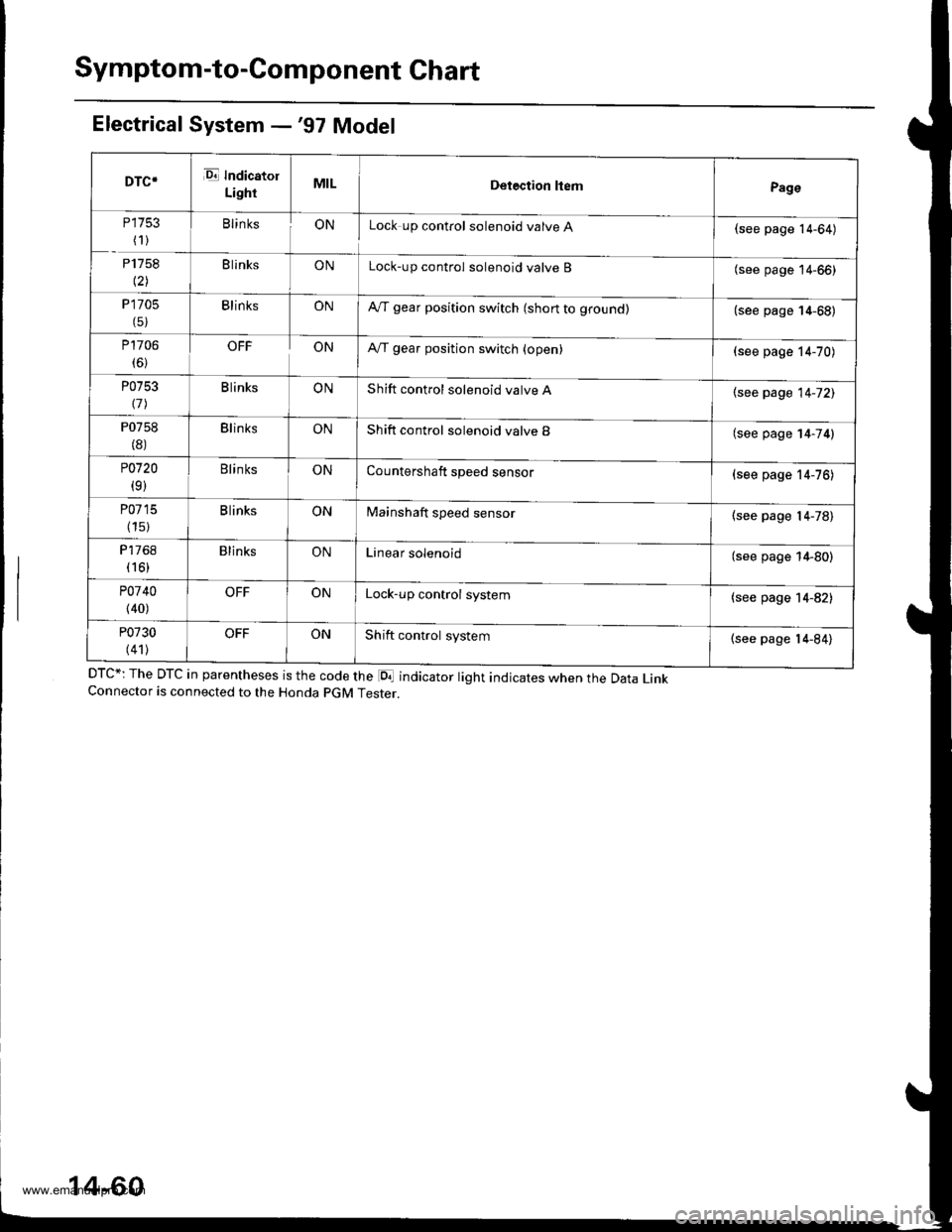
Symptom-to-Component Chart
Electrical System -'97 Model
DTC*: The DTc in parentheses is the code the loa indicator right indicates when the Data LinkConnector is connected to the Honda pGM Tester.
DTC*E Indicatol
LightMILDetection ltemPage
P 1753
(1)BlinksONLock up control solenoid valve A(see page 14-64)
P1758
\21
B linksONLock-up control solenoid valve B(see page 14-66)
P 1705
(5)BlinksONA,/T gear position switch (short to ground)(see page 14-68)
P1706
(6)OFFONA,/T gear position switch {open)(see page 14-70)
P0753
\11
B linksONShift control solenoid valve A(see page 14-72)
P0758
(8)BlinksONShift control solenoid valve B(see page 14-74)
P0720
(9)BlinksONCountershaft speed sensor{see page 14-76)
P0715
(15)B linksONMainshaft speed sensor(see page l4-78)
P17 68( 16)
BlinksONLinear solenoid(see page 14-80)
P0740
{40)
OFFONLock-up control system(see page 14-82)
P0730
(41)OFFONShift control system(see page 14-84)
14-60
www.emanualpro.com
Page 578 of 1395
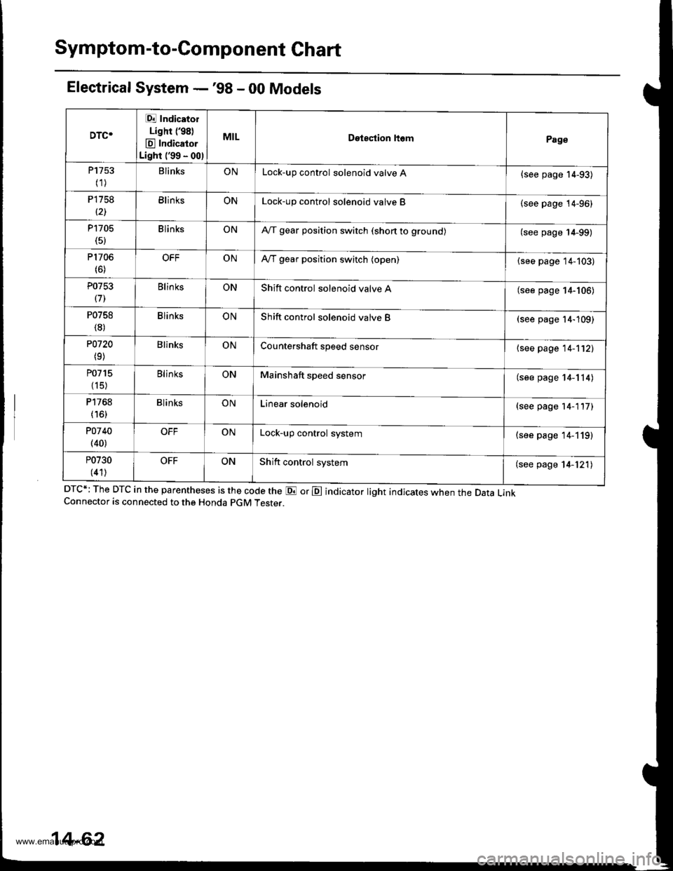
Symptom-to-Component Chart
Electrical System -'98 - 00 Models
DTC*; The DTC in the parentheses is the code the E or E indicator light indicates when the Data LinkConnector is connected to the Honda pGM Tester.
DTC*
Et Indicatol
Lighr (98)
E Indicator
Light ('99 - 00)
MILDetestion ltomPage
P1753
(1)BlinksONLock-up control solenoid valve A{see page 14-93)
P1758
(21BlinksONLock-up control solenoid valve B(see page 14-96)
P1705(5)BlinksONA,/T gear position switch (shon to grounol(see page 14-99)
P1706(6)OFFONA,/T gear position switch (open)(see page 14-103)
P0753
(71Blin ksONShift control solenoid valve A(see page 14-106)
P0758
(8)BlinksONShift control solenoid valve B(see page 14-109)
P0720
(9)BlinksONCountershaft speed sensor{see page 14-112)
P0715
{15)
BlinksONMainshaft speed sensor(see page 14-114)
P1768
(16)BlinksONLinear solenoid(see page 14-117)
POl 40(40)OFFONLock-up control system(see page 14-119)
P0730
(41)OFFONShift control system(see page 14-121)
14-62
www.emanualpro.com
Page 670 of 1395
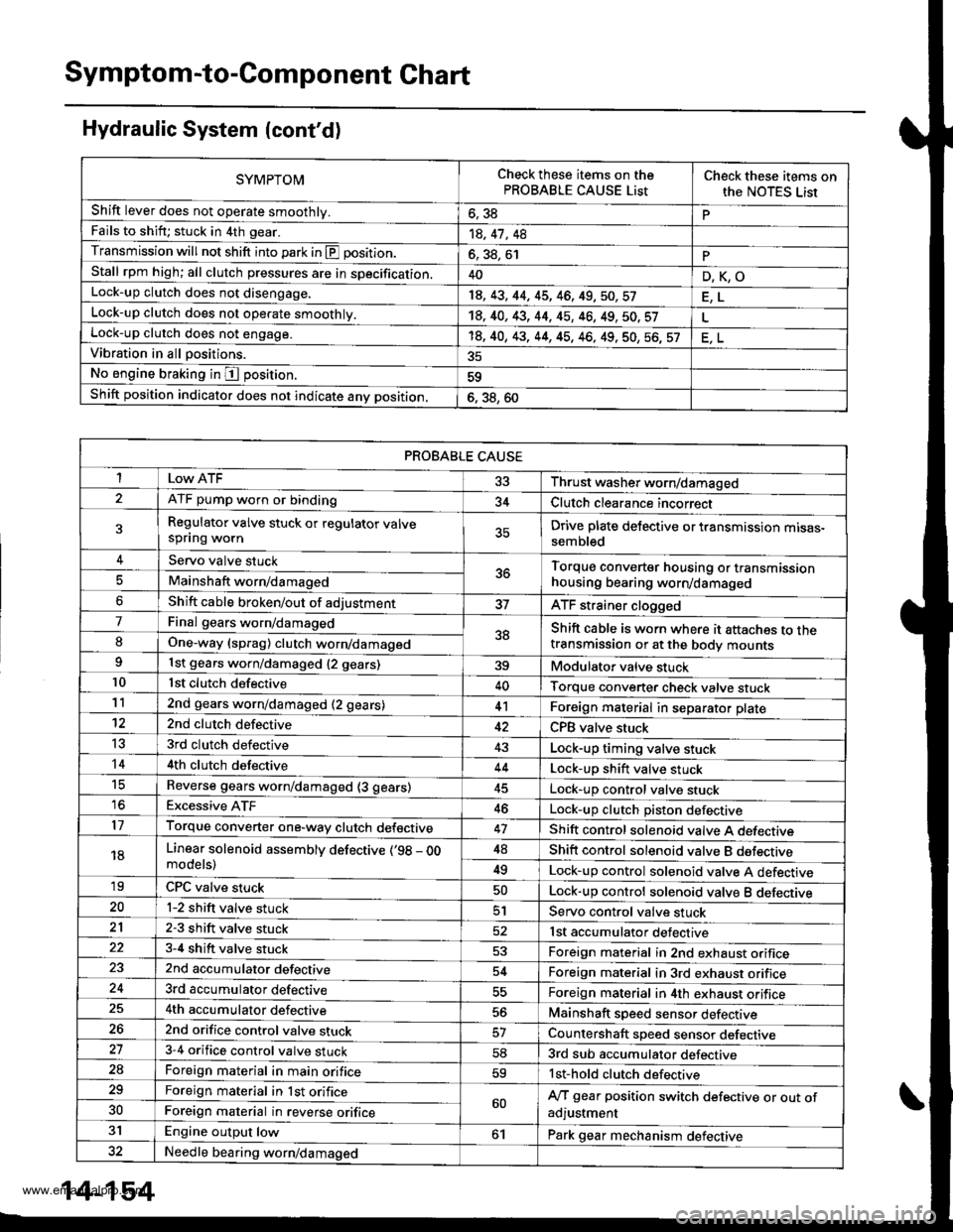
Symptom-to-Component Chart
Hydraulic System (cont'd)
SYMPTOMCheck these items on thePROBABLE CAUSE ListCheck these items onthe NOTES Lisr
Shift lever does not operate smoothly.o, JdPFails to shift; stuck in 4th gear.14, 41 , 48
Transmission will not shift into park in E position.6, 38, 61PStall rpm high; all clutch pressures are in specification.40D,K,OLock-up clutch does not disengage.18, 43, 44, 45, 46, 49,50,57
Lock-up clutch does not operate smoothly.14, 40, 43, 44, 45, 46, 49, 50. 57Lock-up clutch does not engage.'t8, 40, 43, 44, 45, 46, 49, 50, 56, 57Vibration in all positions.
No engine braking in I position.59
Shift position indicator does not indicate anv position,6. 38, 60
PROBABLE CAUSE
I 33 Thrust washer worn/damaged
ATF pump worn or binding34Clutch clearance incorrect
Regulator valve stuck or regulator valvespflng wornDrive plate delective or transmission mtsas-sembled
Servo valve stuck5ttTorque converter housing or transmissionhousing bearing worn/damagedMainshaft worn/damaged
Shift cable broken/out of adjustmentATF strainer clogged
7Final gears worn/damaged38Shift cable is worn where it attaches to thetransmission or at the body mountsIOne-way (sprag) clutch worn/damaged
1st gears worn/damaged {2 gears)39Modulator valve stuck10lst clutch defective40Torque converter check valve stuck112nd gears worn/damaged (2 gears)41Foreign material in separator plate't22nd clutch defectiveCPB valve stuck
t53rd clutch defective43Lock-up timing valve stuck144th clutch defective44Lock-up shift valve stucktcReverse gears worn/damaged (3 gears)Lock-up control valve stuck16Excessive ATF46Lock-up clutch Diston defective17Torque converter one-way clutch defective47Shift control solenoid valve A defecttve
18Linear solenoid assemblv defective (,98 - OOmodels)48Shift control solenoid valve B dsfectrve
49Lock-up control solenoid valve A defective'19CPC valve stuckLock-up control solenoid valve B deleqtve20l-2 shift valve stuck51Servo control valve stuck212-3 shift valve stuck52lst accumulator defective3-4 shift valve stuck53Foreign material in 2nd exhaust orifice2nd accumulator defective54Foreign material in 3rd exhaust orifice3rd accumulator defectiveForeign material in 4th exhaust orifice4th accumulator defective56Mainshaft speed sensor defective262nd orifice control valve stuckCountershaft speed sensor defective273-4 orifice control valve stuck583rd sub accumulator defective2aForeign material in main orifice59lst-hold clutch defective29Foreign material in lst orifice60A/T gear position switch defective or out ofadjustment30Foreign material in reverse orifice
31Engine output low61Park gear mechanism defective32Needle bearing worn/damaged
14-154
www.emanualpro.com
Page 948 of 1395
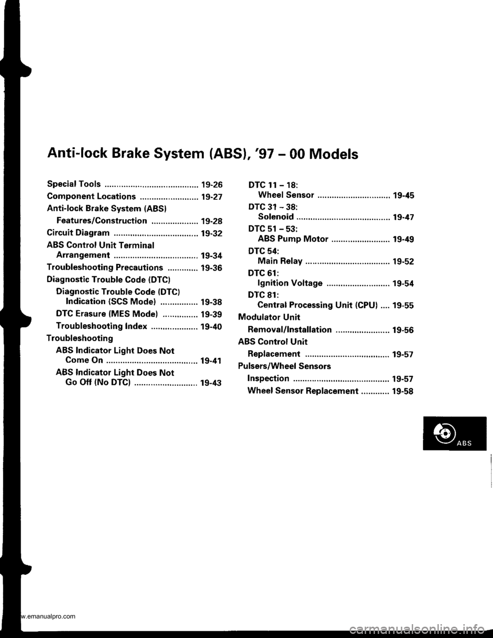
Anti-lock Brake System (ABSI,'97 - 00 Models
Special Tools ............. 19-26
Component Locations ......................... 19-27
Anti-lock Brake System (ABS)
Features/Construction ............. ......, 19-2A
Circuit Diagram ......... 19-32
ABS Control Unit Terminal
Arrangement ......... 19-34
Troubleshooting Precautions ............. 19-36
Diagnostic Trouble Gode (DTC)
Diagnostic Trouble Code (DTC)
Indication (SCS Model ................ 19-38
DTG Erasure (MES Mode) ............... 19-39
Troubleshooting lndex .................... 19-40
Troubleshooting
ABS Indicator Light Does Not
Come On ............ 19-41
ABS Indicator Light Does Not
Go Off (No DTC) ........................... 19-43
DTC 1r - 18:
Wheel Sensor .... 19-45
DTC 31 - 38:
Solenoid ............. 19-47
DTC 51 - 53:
ABS Pump Motor ......................... 19-49
DTC 54:
Main Relay ......... 19-52
DTC 61:
lgnition Voltage ........................... 19-54
DTC 81:
Central Processing Unit (CPU) .... 19-55
Modulator Unit
Removal/lnstallation ....................... 19-56
ABS Control Unit
Replacement ..,...... 19-57
Pulsers/Wheel Sensors
Inspection .............. 19-57
Wheel Sensor Replacement ............ 19-58
www.emanualpro.com
Page 952 of 1395
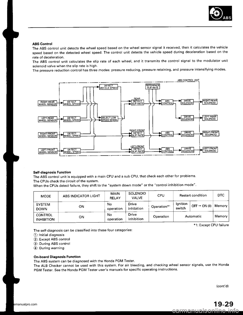
ABS Control
The ABS control unit detects the wheel speed based on the wheel sensor signal it received, then it calculates the vehicle
speed based on the detected wheel speed. The control unit detects the vehicle speed during deceleration based on the
rate of deceleration.
The ABS control unit calculates the slip rate of each wheel, and it transmits the control signal to the modulator unit
solenoid valve when the slip rate is high
The pressure reduction control has three modes: pressure reducing, pressure retaining, and pressure intensi{ying modes.
Self-diagnosis Function
The ABS control unit is equipped with a main cPU and a sub cPU, that check each other for problems.
The CPUs check the circuit of the system.
When the CPUS detect failure, they shift to the "system down mode" or the "control inhibition mode".
The self-diagnosis can be classitied into these four categories:
O: Initial diagnosis
O: Except ABS control
O; During ABS control
@: During warning
On-board Diagnosis Function
The ABS system can be diagnosed with the Honda PGM Tester.
The ALB Checker cannot be used with this system. For air bleeding. and checking wheel sensor signals, use the Honda
PGIM Tester. See the Honda PGM Tester user's manuals for specific operating instructions.
(cont'd)
19-29
ABS CONTROL I-INIT
MODEABSINDICATOR LIGHTMAIN
RE LAY
SOLENOID
VALVERestan conditionDTC
SYSTEM
DOWNONNo
operatron
Drive
inhibitionOperation*rlgnition
switchOFF - oN (ll)Memory
CONTROL
INHIBITIONONNo
operaton
Drive
inhibitionOperationAutomaticlVemory
*1: Except CPU failure
www.emanualpro.com