Harness HONDA CR-V 1999 RD1-RD3 / 1.G Workshop Manual
[x] Cancel search | Manufacturer: HONDA, Model Year: 1999, Model line: CR-V, Model: HONDA CR-V 1999 RD1-RD3 / 1.GPages: 1395, PDF Size: 35.62 MB
Page 1214 of 1395
lgnition Switch
Test
SRS components are located in this area. Review the
SRS component locations, precautions, and procedures
in the SRS section {24} before performing repairs or ser
vtce.
L lMake sure you have the anti-theft code for the
radio, then write down the frequencies for theradio's preset buttons (wilh anti-theft feature).
2. Disconnect the battery negative cable.
3. Remove the driver's dashboard lower cover and the
knee bolster {see section 20).
4. Disconnect the 5P connector from the under-dash
fuse/relay box and the 3P connector from the main
wtre narness,
5P CONNECTOR
Wire side oftemale terminals
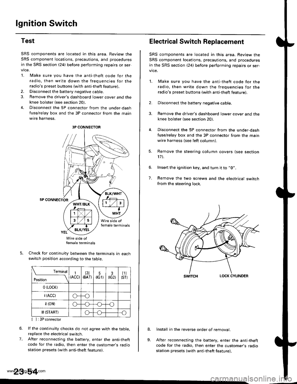
Check tor continuity between the terminals in eachswitch position according to the table.
rernrnal
ros[ron \
I(ACC)I3l{BAT}5flG1)30G2iI1llsrl
0 (LocK)
r(Acclo--o
fl (oN)G_o
III (START)o--.o
7.
{ I | 3P connector
lf the continuity checks do not agree with the table,replace the electrical switch.
After reconnecting the battery, enter the anti-theftcode for the radio, then enter the customer's radio
station presets (with anti-theft feature).
23-54
3P CONNECTOR
Electrical Switch Replacement
SRS components are located in this area. Review the
SRS component locations, precautions, and procedures
in the SRS section {24) before performing repairs or ser-vice.
1. Make sure you have the anti-thett code for the
radio, then write down the frequencies for the
radio's preset buttons (with anti-theft feature).
2. Disconnect the battery negative cable.
3. Remove the driver's dashboard lower cover and the
knee bolster (see section 20).
4. Disconnect the 5P connector from the under,dash
tuse/relay box and the 3P connector f.om the main
wire harness {see left column).
7.
Remove the steering column covers (see section'17 t.
Insert the ignition key, and turn it to "0".
Remove the two screws and the electrical switchfrom the steering lock,
swrTcHLOCK CYLINDER
lnstall in the reverse order of removal.
After reconnecting the battery, enter the anti-theftcode for the radio, then enter the customer's radiostation presets (with antj-theft feature).
9.
www.emanualpro.com
Page 1222 of 1395
Vehicle Speed Sensor (VSSI
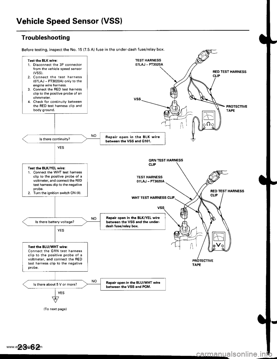
T6st tho BLK wirei1. Disconnect the 3P connectorfrom the vehicle speed sensor{VSS).2. Connect the test harness
{07LAJ - PT3020A) only to theengine wire harness.3. Connect the FED test harnessclip to the positive probe of anohmmeter,4. Check for continuity betweenthe RED test harness clip andbody ground.
Repair open in the BLK wirebetwGon the vSS .nd G101.
T.st the BLK/YEL wire:1. Connect the WHT test harnessclip to the positive probe of avohmeter, and connect the REDtest harness clip to the negativeprobe.2. Turn the ignition switch ON (ll).
Rep.ir op.n in th. BLK/YEL wirebetwaen the VSS rnd the und6r-dash fuse/.6lav box.ls there battery voltage?
Test the BLU/WHT wi.s:Connect the GRN test harnessclip to the posilive probe of avoltmeter. and connect the REDtest harness clip to the negativeprobe.
Repair open in the BLU/WHT wirobstweon the VSS and PCM.ls there about 5 V or more?
Troubleshooting
Before testing, inspect the No. 15 (7.5 A) fuse in the underdash fuse/relay box.
TEST HARNESSOTLAJ - PT3O2OA
RED TEST HARNESS
PROTECTIVETAPE
GRN TEST HARNESSCLIP
TEST HARNESSOTLAJ - PT3O2OA
REOCLIPWHT TEST HARNESS CLIP
(To next page)
23-62
HARNESS
TAPE
www.emanualpro.com
Page 1223 of 1395
o-.
WHT TEST HARNESSCLIP
TEST HARNESSOTLAJ _ PT3O2OA
GRN TEST HARNESS
BED TEST HARNESSct-tP
PROTECTIVETAPE
(From previous page)
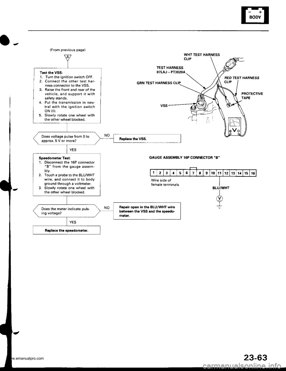
T6st the VSS:1. Turn the ignition switch OFF.2, Connect the other test har-ness connector to the VSS,3. Raise the front and rear of thevehicle, and support jt withsafety stands.4. Put the transmission in neu-tral with the ignition switchoN r).5. Slowly rotate one wheel withthe other wheel blocked.
Does voltage pulse from 0 toapprox, 5 V or more?
Spoodom6tor T6st:1, Disconnect the 16P connector"B" from the gauge assem
2. Touch a probe to the BLUMHTwire. and connect it to bodyground through a voltmeter.3. Slowly rotate one wheel withthe other wheel blocked.
R.p.ir opon in the BLU/WHT wirebetwe€n the VSS and the 3oeedo-mgter.
Does the meter indicate puls-ing voltage?
GAUGE ASSEMBLY 16P CONNECTOR 'B-
Wire side offemale termin6lsBLU/WHT
I(v)
It
23-63
www.emanualpro.com
Page 1266 of 1395
Horns
Switch Test
Disconnect the battery negative cable, then disconnect
the positive cable, and wait at ieastthree minutes.
Disconnect the driver's airbag and front passenger's
airbag connectors (see section 24).
Remove the drive.'s dashboard lower cover and the
knee bolster (see section 20).
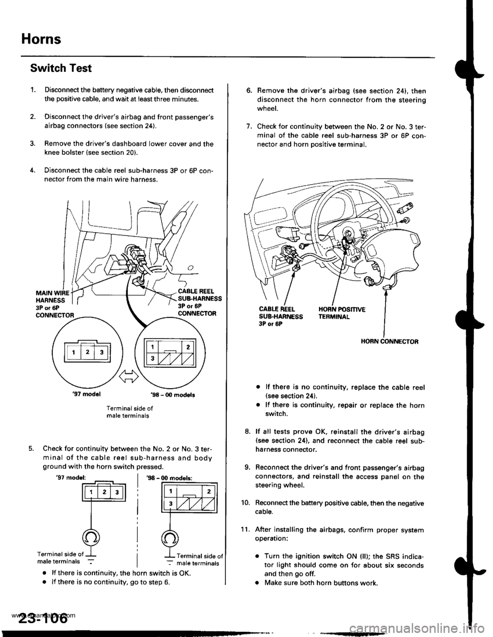
Disconnect the cable reel sub-harness 3P or 6P con-
nector from the main wire harness.
1.
MAIN WIREHARNESS3P o. 6P
CABI.I REELSUB.HARNESS3P or 6PCONNECTORCONNECTOR
37 modol ,98 - 0O modots
Terminal side ofmale terminals
Check for continuity between the No. 2 or No. 3 ter-
minal of the cable reel sub-harness and bodyground with the horn switch pressed.
'97 model:'98 - (X) modols:
Terminalside of
. lf there is continuity. the horn switch is OK.. lf there is no continuity, go to step 6.
23-106
Terminal side of
6.Remove the driver's airbag (see section 241, then
disconnect the horn connector from the steerinq
wneet.
Check for continuity between the No. 2 or No. 3 ter-
minal of the cable reel sub-harness 3P or 6P con-
nector and horn Dositive terminal.
lf there is no continuity, replace the cable reel(see section 24).
lf there is continuity. repair or replace the horn
switch.
lf sll tests prove OK, reinstall the driver's airbag(see section 24), and reconnect the cable reel sub-
harness connector.
Reconnect the driver's and front passenger's airbag
connectors, and reinstall the access panel on the
steering wheel.
Reconnect the battery positive cable, then the negative
cable.
After installing the airbags, confirm proper system
operatron:
. Turn the ignition switch ON (ll); the SRS indica-
tor light should come on for about six seconds
and then go off.
. Make sure both horn buttons work.
7.
11.
8.
9.
10.
HORN CONNECTOR
www.emanualpro.com
Page 1303 of 1395
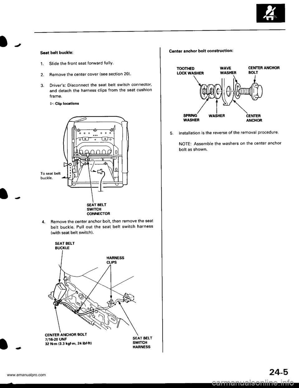
Ssat belt buckle:
1. Slide the front seat forward fully
2. Remove the center cover (see section 20).
3. Driver's: Disconnect the seat belt switch connector,
and detach the harness clips from the seat cushion
frame.
>: Clip locations
To seat beltbuckle.
SEAT BELTswlTcHCONNECTOR
4. Remove the center anchor bolt, then remove the seat
belt buckle. Pull out the seat belt switch harness
(with seat belt switchl.
SEAT BELTBUCKLE
SEAT B€LTSwlTCHHARNESS
CENTER ANCHOR BOLT
7/1&20 UNF32 N.m {3.3 kg{ m, 24 lbf ftl
24-5
Csntor anchor bolt construstion:
TOOTHEDLOCK WASHER
SPRINGWASHERWASHERCENTERANCHOR
WAVE CENTER ANCHOR
WASHER BOLT
5.lnstallation is the reverse of the removal procedure.
NOTE: Assemble the washers on the center anchor
bolt as shown.
www.emanualpro.com
Page 1312 of 1395
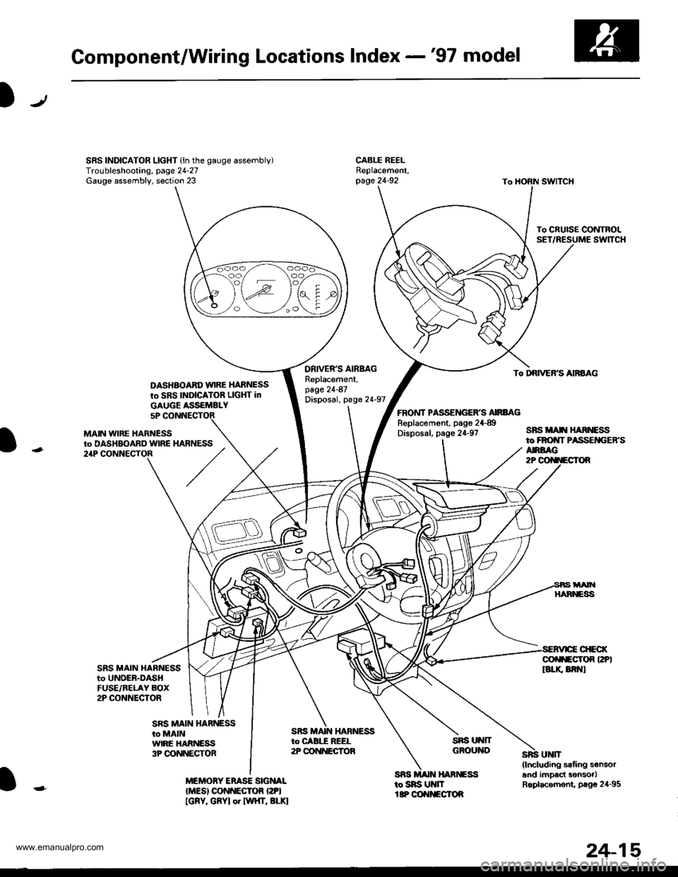
Component/Wiring Locations Index -'97 model
SRS INDICATOR LIGHT (ln the gauge assembly)Troubleshooting, page 24-27Gauge assembly, section 23
DASHBOABD w|RE HARNESS
to SBS INDICATOR LIGHT in
DRIVER'S AIBMGReplacement,page 21-87Disposal, page 24-97
To CRUISE CONTROLSET
To DRIVERS AnBAG
ANBAG2P
sBsitAr[ ] nNEssto FROI|T PASSEiIGEB.S
FRONT PASSEITGER'S AIRBAGReplacement, pago 24{9Disposal, page 24-97
sns ut{fTGROUND
SES MAIN HAR]GSStosns U nItP OOIIITECTOR
MAIN WIRE HABNESSto DASHBOABD wlRE21P
SRS MAIN HABNESSto UNOEB-DASHFUSE/BELAY BOX2P CONNECTOR
GOf$ECrOn PPIlBLr( 8R t
MEMORY ERASE SIGNALIMES) CONNECTOR I2PI[GRY. GRYI or twHT, BLr.l
GAUGE ASSEMBLY5P
HARNESS
SRS MAIN HARNESSto MAINWIRE HARNESS3P OONNECTOR
24-15
www.emanualpro.com
Page 1313 of 1395
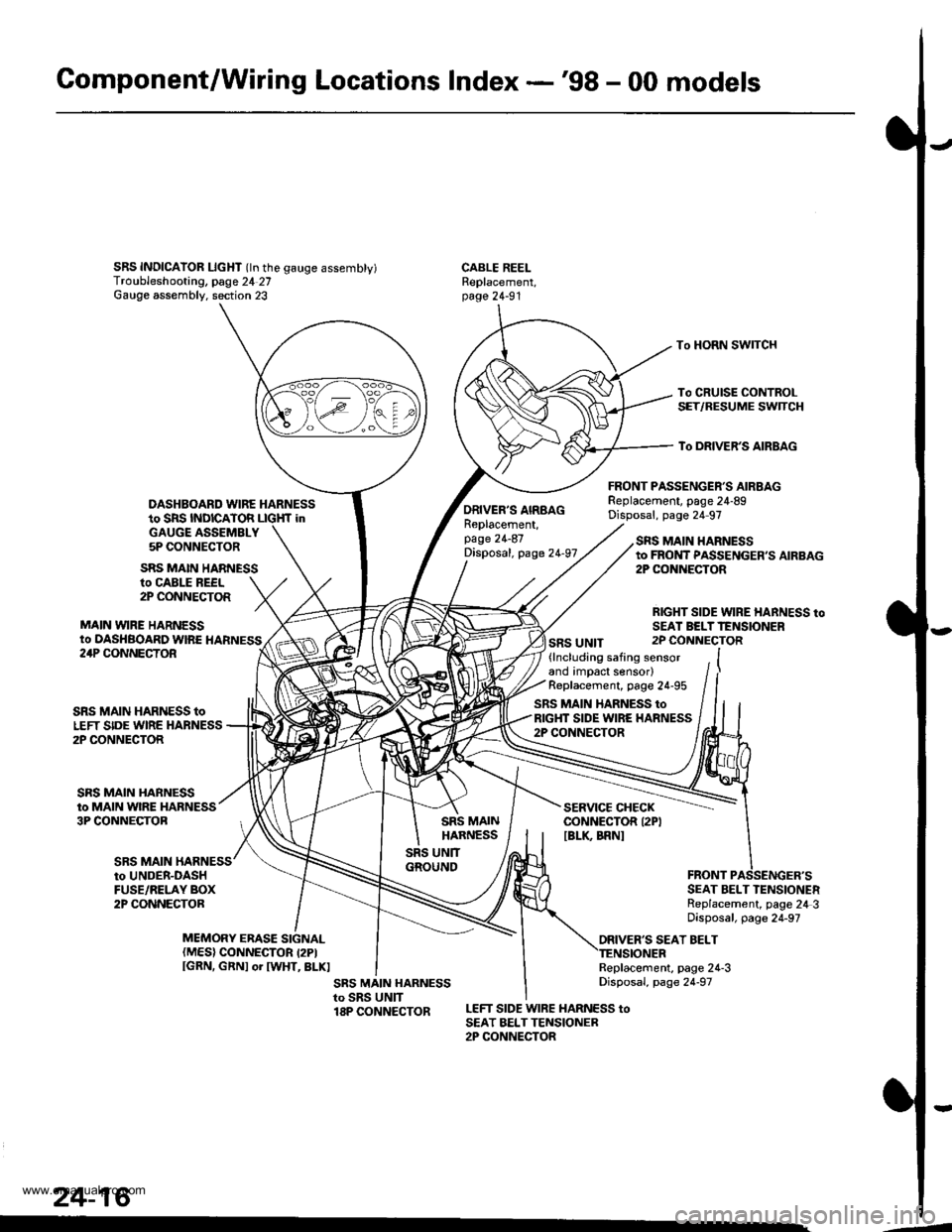
Gomponent/Wiring Locations Index -'98 - 00 models
SRS INDICAIOR LIcHT (ln the gauge assembty)Troubleshooting, page 24 27Gauge assembly. section 23
DASHBOARD WIRE HARNESSto SRS INDICATOR LIGHf inGAUGE ASSEMBLY5P CONNECTOR
FRONT PASSENGER'S AIRBAGReplacement, page 24-89Disposal, page 24 97
CABLE REELReplacement,page 24-91
To HORN SWITCH
To CRUISE CONTROLSET/RESUME SWTCH
To DRIVER'S AIRBAG
ro CABLE REEL2P CONNECTOR
MAIN VYIRE HARNESSto DASHBOARD WIRE HARNESS
SRS MAIN HARNESS
ORIVER'S AIRBAGReplacement,page 24-87Disposal, page 24-97
SRS UNIT
SRS MAIN HARNESSto FROI{T PASSENGER,S AIRBAG2P CONiIECTOR
RIGHT SIDE WIRE HARNESS toSEAI BELTTENSIONER2P CONNECTOR24P CONNECTOR
SRS MAIN
SRS MAIN HARNESS toLEFT SIDE WIRE HARNESS2P CONNECTOR
SRS MAIN HARNESSto MAIN WIRE HARNESS3P CONNECTOB
(lncluding safing sensorand impact sensor)Replacement, page 24-95
SRS MAIN HARNESS toRIGHT SIDE WIRE HARNESS2P CONNECTOR
SERVICE CHECKCONNECTOR I2PIIBLK BRNI
to UNDER-DASHFUSE/RELAY BOX2P CONNECTORSEAT BELT TENSIONERReplacement, page 24 3Disposal, page 24-97
ORIVER'S SEAT BELTMEMORY ERASE SIGNAL(MES) CONNECTOR I2PIIGRN, GRNI or IWHT, BLKIReplacement, page 24-3Disposal, page 24-97
LEFT SIDE WIRE HARNESS toSEAT BELTTENSIONER2P CONNECTOR
24-16
.4
www.emanualpro.com
Page 1315 of 1395
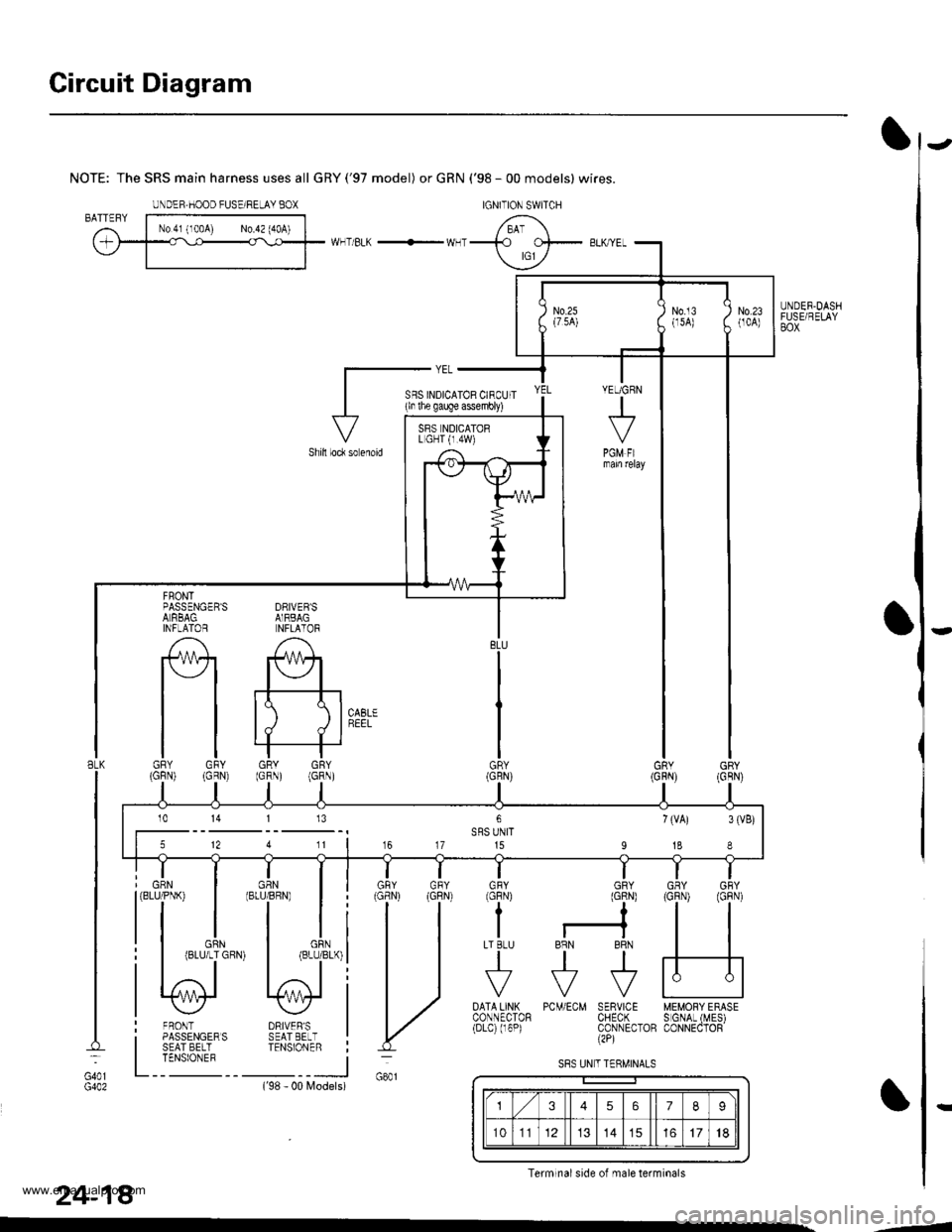
Circuit Diagram
UNDER.DASHFUSE/RELAYBOX
NOTE: The SRS main harness uses all GRY('97 model) or GRN ('98 - 00 models) wires.
WHT/BLK -'- WHT
DRIVEB'SAIRBAGNFLATOR
A
#+
tt tll./ d I
GRY GRY(GRN) (GRN)
FRONTPASSENGER'SALRBAGINFLAlOR
tlGRY GFY(GFN) (GRN)
DRIVER'SSEAT EELTTENSIONER
FRONTPASSENGERSSEAT BELTTENSIONEF
GRN(BLU/PNK)
BLK
G401
24-18
PCM/ECM SERVICE MEMORY ERASECHECK S GNAL (MES)CONNECTOB CONNECTOR(2P)
DATA LINXCONNECTOR(Drc) (r6P)
Models)('98 - 00
IGNITION SWITCHUNDEF,HOOD FUSE/RELAY BOX
YEUGRN
+
PGM FImam relay
SFS INDICATOR CIRCUIT(ln lhe gauge assembly)
Shill loc* so enoid
BLU
GR\
GNY GRY
H
GFY GRYlcFNt (GlN)
??
I r-?LT BLU BRN BRN
tttr?F?F
VVV
SRS NDICATORL GHT {r.4W)
5 12 4 11 | 16 17 15 I 18 I
10 14 113
U
S8S UN T TERMINALS
3567I
101114151718
Terminal side of male terminals
-4
www.emanualpro.com
Page 1317 of 1395
Precautions/Procedures
SRS Unit Precautions
Take extra care when painting or doing body work in
the area below the dashboard. Avoid direct exposure
of the SRS unit or wiring to heat guns, welding, or
spraying equipment.
Disconnect the driver's/front passenger's airbag con-
nectors and seat belt tensioner connectors before
working below the dashboard near the SRS unit.
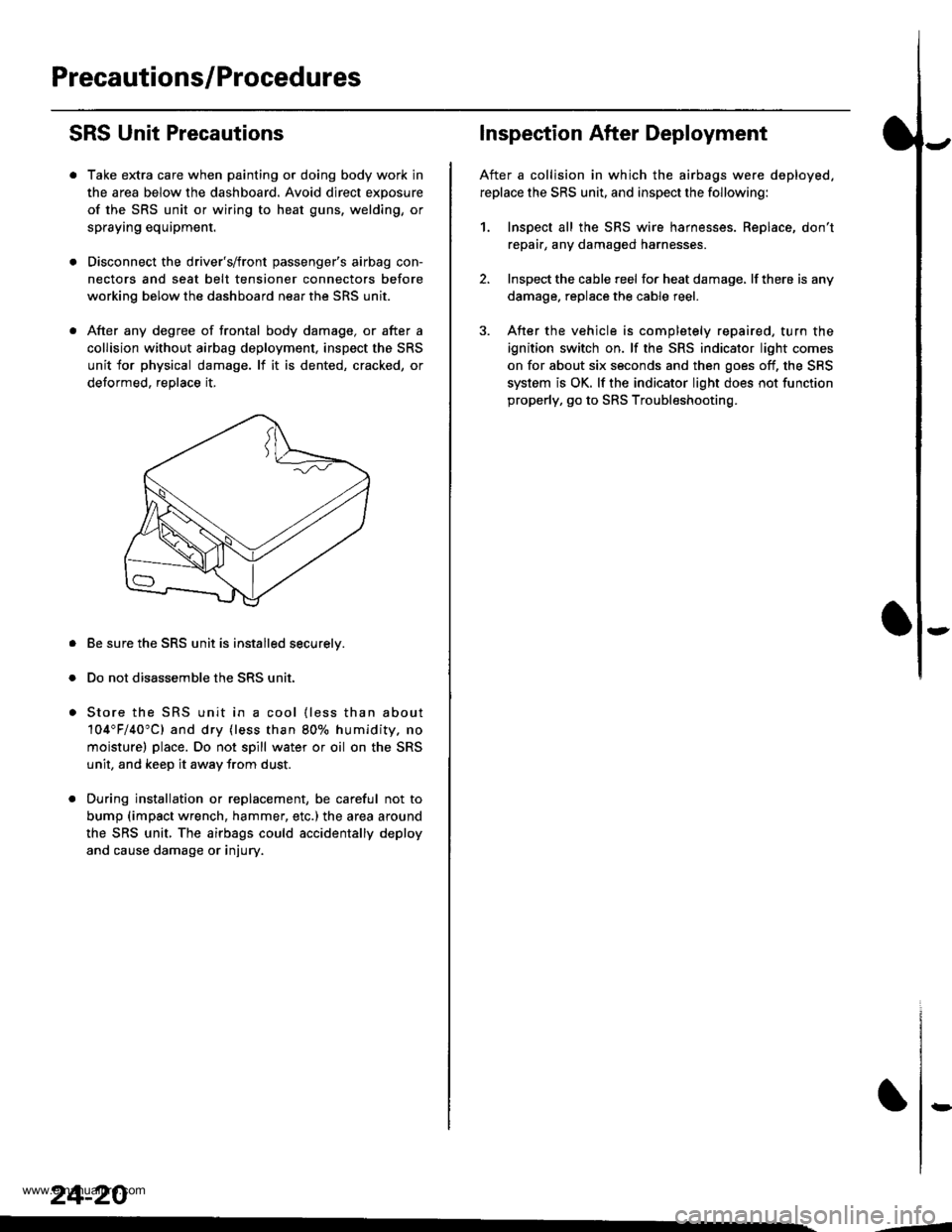
After any degree of frontal body damage, or after a
collision without airbag deployment, inspect the SRS
unit for physical damage. lf it is dented, cracked, or
detormed, reolace it,
Be sure the SRS unit is installed securelv.
Do not disassemble the SRS unit.
Store the SRS unit in a cool {less than about
104"F/40"C) and dry {less than 80o/o humidity. no
moisture) place. Do not spill water or oil on the SRS
unit, and keep it awav from dust.
During installation or replacement, be careful not to
bump (impact wrench, hammer, etc.) the area a[ound
the SRS unit, The airbags could accidentally deploy
and cause damage or injury.
24-20
,..4
Inspection After Deployment
After a collision in which the airbags were deployed.
replace the SRS unit, and inspect the following:
1. Inspect all the SRS wire harnesses. Replace, don't
repair, any damaged harnesses
2. Inspect the cable reel for heat damage, lf there is any
damage. replace the cable reel.
3. After the vehicle is completely repaired, turn the
ignition switch on. lf the SRS indicator light comes
on for about six seconds and then goes off, the SRS
system is OK. lf the indicator light does not function
properly, go to SRS Troubleshooting.
rD
www.emanualpro.com
Page 1318 of 1395
JWiring Precautions
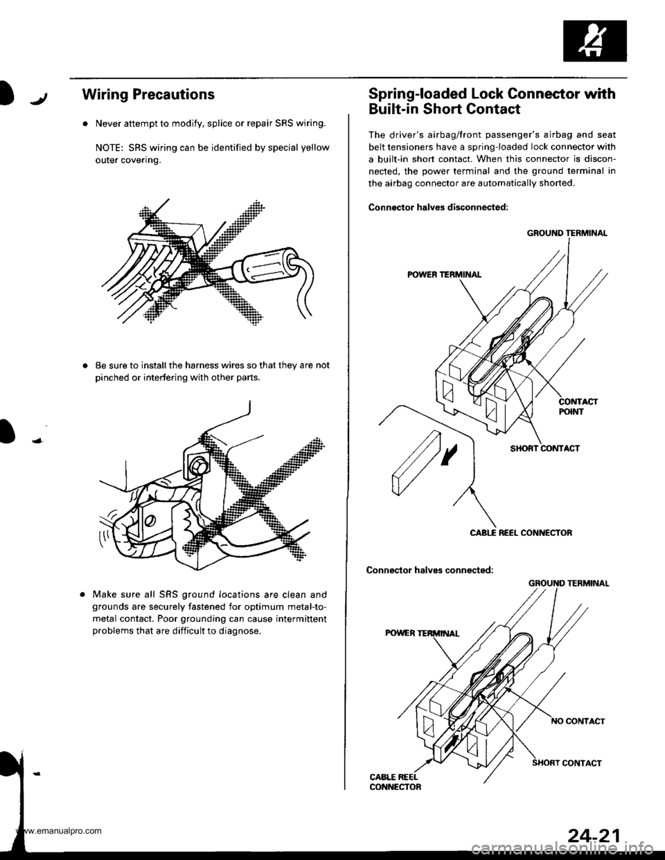
. Never attempt to modify, splice or repair SRS wiring.
NOTE: SRS wiring can be identified by special yellow
outer coveflng.
Be sure to install the harness wires so that they are
pinched or interfering with other parts.
Make sure all SRS ground locations are clean and
grounds are securely fastened for optimum metal-to-
metal contact. Poor grounding can cause intermittent
problems that are difficult to diagnose.
GROUND TERMINAL
CONTACT
CONTACT
24-21
Spring-loaded Lock Connestor with
Built-in Short Gontact
The driver's airbag/front passenger's airbag and seat
belt tensioners have a spring-loaded lock connector with
a built-in short contact. When this connector is discon-
nected, the power terminal and the ground terminal in
the airbag connector are automatically shorted.
Conngctor halvcs diSconnested:
GROUND TERMINAL
SHORT CONTACT
CABIf REEL CONNECTOR
Connector halves connected;
ACT
www.emanualpro.com