Circuit HONDA CR-V 1999 RD1-RD3 / 1.G Workshop Manual
[x] Cancel search | Manufacturer: HONDA, Model Year: 1999, Model line: CR-V, Model: HONDA CR-V 1999 RD1-RD3 / 1.GPages: 1395, PDF Size: 35.62 MB
Page 952 of 1395
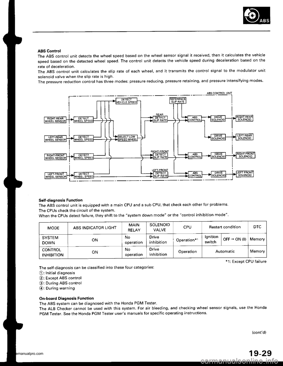
ABS Control
The ABS control unit detects the wheel speed based on the wheel sensor signal it received, then it calculates the vehicle
speed based on the detected wheel speed. The control unit detects the vehicle speed during deceleration based on the
rate of deceleration.
The ABS control unit calculates the slip rate of each wheel, and it transmits the control signal to the modulator unit
solenoid valve when the slip rate is high
The pressure reduction control has three modes: pressure reducing, pressure retaining, and pressure intensi{ying modes.
Self-diagnosis Function
The ABS control unit is equipped with a main cPU and a sub cPU, that check each other for problems.
The CPUs check the circuit of the system.
When the CPUS detect failure, they shift to the "system down mode" or the "control inhibition mode".
The self-diagnosis can be classitied into these four categories:
O: Initial diagnosis
O: Except ABS control
O; During ABS control
@: During warning
On-board Diagnosis Function
The ABS system can be diagnosed with the Honda PGM Tester.
The ALB Checker cannot be used with this system. For air bleeding. and checking wheel sensor signals, use the Honda
PGIM Tester. See the Honda PGM Tester user's manuals for specific operating instructions.
(cont'd)
19-29
ABS CONTROL I-INIT
MODEABSINDICATOR LIGHTMAIN
RE LAY
SOLENOID
VALVERestan conditionDTC
SYSTEM
DOWNONNo
operatron
Drive
inhibitionOperation*rlgnition
switchOFF - oN (ll)Memory
CONTROL
INHIBITIONONNo
operaton
Drive
inhibitionOperationAutomaticlVemory
*1: Except CPU failure
www.emanualpro.com
Page 953 of 1395
Anti-lock Brake System (ABS)
Features/Gonstruction (cont'd)
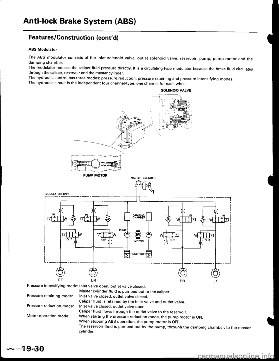
ABS Modulator
The ABS modulator consists of the inlet solenoid valve, outlet solenoid valve, reservoir, pump, pump motor and thedampjng chamber.
The modulator reduces the caliper fluid pressure directly. lt is a circulating-type modulator because the brake fluid circulatesthrough the caliper, reservoir and the master cylinder.The hydraulic control has three modes: pressure reduction, pressure retaining and pressure intensifying modes.The hydraulic circuit is the independent four channel-type, one channel for each wheel.
SOLENOID VALVE
t-
Pressure intensifying mode: Inlet valve open, outlet valve closed,
Pressure retaining mode:
Pressure reduction mode:
Motor operation mode:
Master cylinder fluid is pumped out to the caliper.Inlet valve closed, outlet valve closed.
Caliper fluid is retained by the inlet valve and outlet valve.Inlet valve closed, outlet valve ooen
Caliper fluid flows through the outlet valve to the reservoir.When starting the pressure reduction mode. the pump motor is ON.When stopping ABS operation, the pump motor is OFF.The reservoir fluid is pumped out by the pump, through the damping chamber, to the mastercylinder.
PUMP MOTOR
19-30
www.emanualpro.com
Page 955 of 1395
![HONDA CR-V 1999 RD1-RD3 / 1.G Workshop Manual
Circuit Diagram
UNDFS I]OOD FISAFELAY 8OXCbsod: &rrc ped. deprelled
wHT/GrN -tjF GFrlrrvril
GNITION
*oJG\*"\€F*,-
UNDER-HOOD A8S FUSE/FELAY BOX3P CONNECTOR (O number)
t_--t l-|ll"1
UNDER.HOOO A8 HONDA CR-V 1999 RD1-RD3 / 1.G Workshop Manual
Circuit Diagram
UNDFS I]OOD FISAFELAY 8OXCbsod: &rrc ped. deprelled
wHT/GrN -tjF GFrlrrvril
GNITION
*oJG\*"\€F*,-
UNDER-HOOD A8S FUSE/FELAY BOX3P CONNECTOR (O number)
t_--t l-|ll"1
UNDER.HOOO A8](/img/13/5778/w960_5778-954.png)
Circuit Diagram
UNDFS I]OOD FISAFELAY 8OXCbsod: &rrc ped. deprelled
wHT/GrN -tjF GFrlrr'vril
GNITION
*oJG\'*"\€F*,-
UNDER-HOOD A8S FUSE/FELAY BOX3P CONNECTOR (O number)
t_--t l-|ll'"1
UNDER.HOOO A8S FUSE/RELAY BOX2P CONNECTOF (! numbor)
EFIAKE SWITCH CONNECTOR
l€-4| 1 txl2 |
f s a'lLr--'--.----1
UNDER,DASH FUSFJRELAY BOX20P CONNECTOR (O number)M-OD U LATOR UN IT CON N ECTOR
ll3 2ir I
{tT6TsF}
!]q:]j_1,
MP MOTOR CONNECTORnumber)
ATi)
PU
UNDER-DASH FUSE/RELAY BOX18P CONNECTOR (E number)
(tr
ASSEMBLY 5P CONNECTOR
----.4-l1)/l3l/l5l
356J89
10111213,/ 115 ,/19
123456
910'1213|i4 /718
19-32
Wire side ol female lerminals
Terminal side oJ lemale terminals
www.emanualpro.com
Page 964 of 1395
Troubleshooting
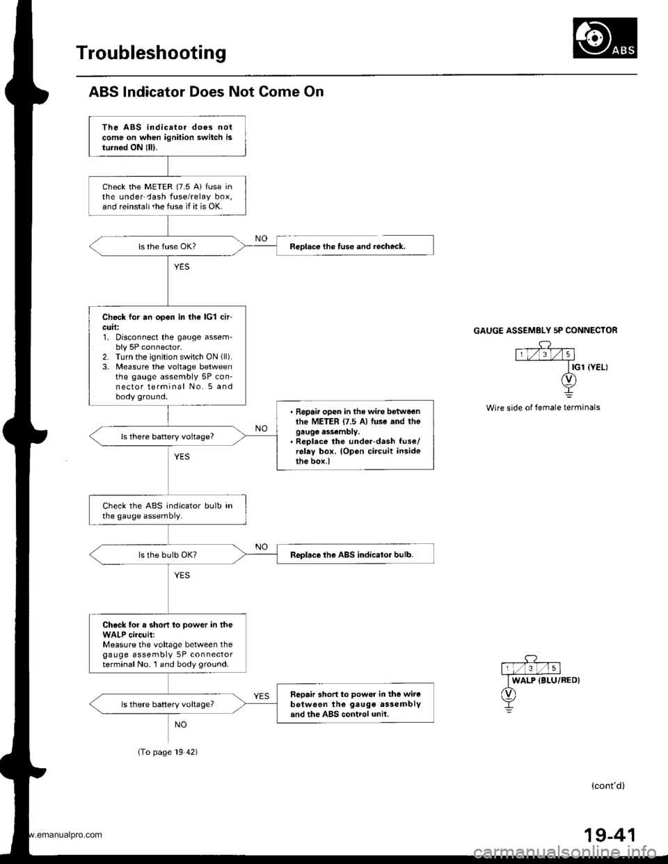
ABS lndicator Does Not Come On
The ABS indicator does notcome on when ignition switch isturnod ON lll).
check the METER {7.5 A} fuse inthe underCash fuse/relay box,and reinstaltthe fuse if it is OK.
Check for an open in the lcl ch-cuil:1. Disconnect the gauge assem-bly 5P connector.2. Turn the ignition switch ON (ll).
3. Measure the voltage betweenthe gauge assembly 5P con-nector terminal No. 5 andbody ground.
. Repair open in the wire betweenlhe METER {7.5 A) luse and thogauge assembly.. Reolece the under-dash fuse/relay box. (Opon circuit insidethe box.)
ls there battery voltage?
Check the ABS indicator bulb inthe gauge assembly.
Replace the ABS indicator bulb.
Check for a short to power in theWALP circuit:Measure the voltage between thegauge assembly 5P connectorterminal No. 1 and body ground.
Sepair short to power in the witeb€tween the gaug€ assemblyand the ABS control unil.ls there battery voltageT
Reolace the tuse and recheck.
(To page 19 42)
GAUGE ASSEMBLY 5P CONNECTOR
Wire side of female terminals
(cont'd)
19-41
www.emanualpro.com
Page 965 of 1395
Troubleshooting
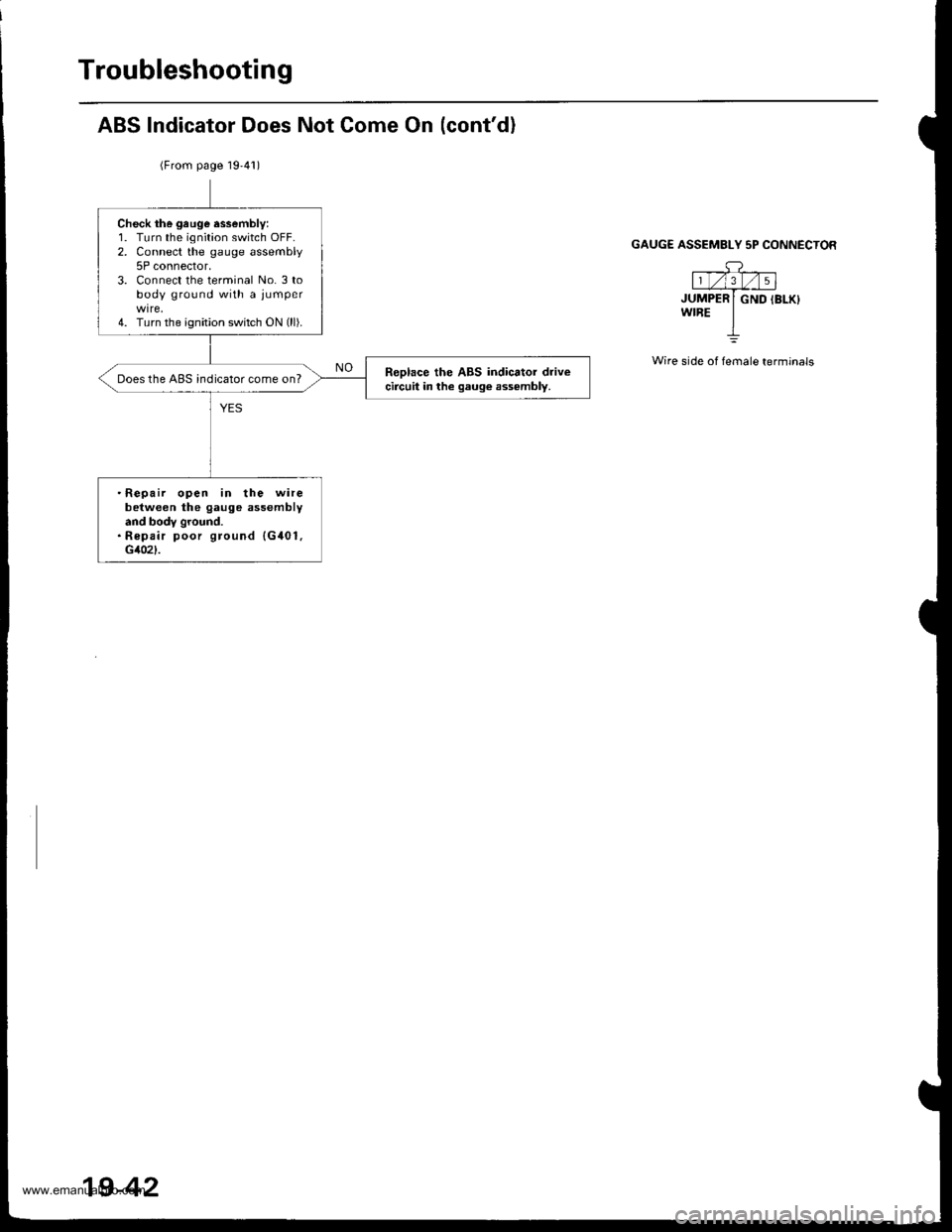
ABS Indicator Does Not Come On (cont'd)
(From page 19'41)
GAUG€ ASSEMBLY 5P CONNECTOR
---g-l1 t/l3_l/ | 5 |JUMPER I GND IBLK}wrBE IL
Wire side of female terminals
Check the gruge essembly:1. Turn the ignition switch OFF.2. Connect the gauge assembly5P connector,3. Connect the terminal No. 3 tobody ground with a jumper
4. Turn the ignition switch ON (ll).
Reolace the ABS indicator drivecircuit in the gaug€ ass€mbly.Does the ABS indicator come on?
.Repair open in the wirebetween the gauge assemblyand body ground.. Repair poor ground {G401,c102l-
19-42
www.emanualpro.com
Page 966 of 1395
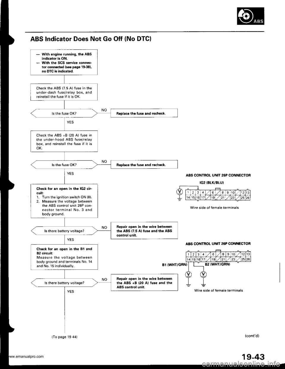
- With engine running, the ABSindicsior is ON.- With the SCS service connec-tor conn€cted (s€€ page 19381,no DTC is indicated.
Check the ABS {7.5 A) fuse in theundeFdash fuse/relay box, andreinstall the fuse if it is OK.
ReDlace lhe tuse and recheck.
Check the ABS +B (20 A) fuse inthe underhood ABS fuse/relaybox, and reinstall the fuse if it isoK.
Replace the fuse and rocheck.
Check for sn open in the lG2 cir-cuit:1. Turn the ignition switch ON {ll).2. Measure the voltage betweenthe ABS control unit 26P con-nector terminal No. 3 andbody ground.
Repair open in tho wire betweenthe ABS {7.5 A} fu3e .nd the ABScontrol unit,
Check for an open in the 81 and82 circuit:Measure the voltage betweenbody ground and terminals No. 14and No. 15 individually.
Ropair open in tho wi.e betweenrhe ABS +B {20 A) fuse and theABS control unit.is there battery voltage?
ABS Indicator Does Not Go Off (No DTGI
A8S CONTROL UNIT 26P CONNECTOR
IG2IBLK/BLU)
Wire side of female terminals
ABS CONTROL U N 26P CONf{ECTOR
{WHT/GRNI
(cont'd)
Wire side of female terminals
(To page 19 44)
19-43
www.emanualpro.com
Page 967 of 1395
Troubleshooting
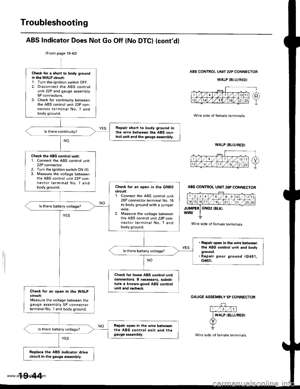
ABS Indicator Does Not Go Off (No DTC) (cont'dl
ABS CONTROL UNIT 22P CONNECTOR
WALP {BLU/REDI
Wire side of female terminals
JUMPCRWIREGND2IBLKI
GAUGE ASSEMBLY 5P CONNECTOF
(From page 19,43)
Check tor a short to body groundin the WALP circuil:1. Turn the ignition switch OFF.2. Disconnect the ABS controlunit 22P and gauge assembly5P connectors.3. Check lor continuity betweenthe ABS control unit 22P con-nector terminal No. 7 andbody ground.
Repair short to body ground inthe wire between the ABS con-t.ol unh and the gauge assembly.
Check the ABS control unit:1. Connect the ABS control unit22P connector.2. Turn the ignition switch ON (ll).3. Measure the voltage betweenthe ABS control unit 22P con-nector terminal No. 7 andbody ground.Check tor an open in the GND2circuit:1. Connect the ABS control unit26P connecto. terminal No. 16to body ground with a jumper
2. Measure the voltage betweenthe ABS control unit 22P con-nector terminal No. 7 andbody ground.
ls there battery voltage?
. Repeir op6n in th6 wire ttetweenthe ABS control unit and bodyground.. Rep.ir poor ground {G401,G4021.
Check lor loose ABS control unhconnectors. lf necesssry, substi-tuie e lnown-good ABS controlunit and recheck.Check tor an open in the WALPcircuit:Measure the voltage between thegauge assembly 5P connectorterminal No. 1 and body ground.
Repair op6n in the wi.e botw€enthe ABS control unit and th€gau9e ass€mbly.
ls there battery voltage?
Replaco the ABS indicator drivecircuit in the gauge assembly.
ABS CONTROL UNIT 26P CONNECTOR
Wire sade of female terminals
WALP IBLU/FEDI
19-44
www.emanualpro.com
Page 968 of 1395
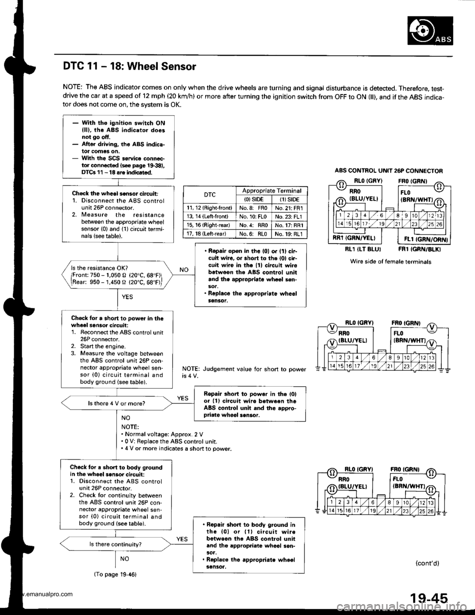
- With ths ignition switch ONllll, the ABS indicatol doesnot go ott.- Atte. driving, the ABS indica-lot comas on.- With the SCS service connec-tor connocted (s€€ page 19.381,DTGr 11 - 18 sre indbated.
Check the whcol sensor circuit:1. Disconnect the ABS controlunit 26P connector.2, Nleasure the resistancebetween the appropriate wheelsensor l0) and 1'l) circuit termi-nals {see table).
. Ropair op€n in th. {01 o. lll cir-cuit wire, oa short to the (01 cir-cuit wire in the lll circuit wirobetweon the ABS control unitand th. appropriate whasl sen-sot.. Roplace the rpp.opriatc whe6lSensor.
ls the resistance OK?
/Fronr:750 - r,050 o (20"C,68"F\
\Rear: 950 -'1,450 O (20"C, 68'F,
Chock lor a short 10 power in thewheel sensoa ciacuil:1. Reconnect the ABS control unit26P connector.2. Start the engine.3. Measure the voltage betlveenthe ABS control unit 26P con-nector appropriate wheel sen-sor (0) circuit terminal andbody ground (see table).
Ropair lhort to pow.r in the l0lot 11) circuit wiro between theABS control unit and the appro-priate whool sen6or.
ls there 4 V or more?
Check for a short to body groundin the whoal s.n3or cilcuit:1. Disconnect the ABS controlunit 26P connector.2. Check lor cont;nuity betweenthe ABS control unit 26P con-nector appropriate wheel sen-sor {0) circuit terminal andbody ground {se6 table).. Ropair short to body g.ound inth6 {01 or {1} circuit wirebotweon th6 ABS cont.ol unitand tho appropriato wheol son-aot.. Roplace tho appropriate wheelsensot.
DTC 11 - 18: Wheel Sensor
NOTE: The ABS indicator comes on only when the drive wheels are turning and signal disturbance is detected, Therefore, test-drive the car at a speed of 12 mph (20 km/h) or more after turning the ignition switch from OFF to ON l), and if the ABS indica-tor does not come on, the svstem is OK.
RLl (LT BLUI FRl IGRN/BLKI
Wire side of female terminals
NOTE: Judgement value for short
NO
NOTE:. Normalvoltage: Approx. 2 V.0 V: Replace the ABS control unit.. 4 V or more indicates a shon to power.
NO(cont'dl
ABS CONTNOL UNIT 26P CONNECTOR
RROIBLU/YEL}
RRT IGRN/YELI
FLO(BRN/WHTI
FLl IGFN/ORN}
DTCAppropriate Terminal
{0}srDE(1)S|DE
11, l2lRight-front)No.8: FnoNo.21: FR1
13, 14 (Left-front)No. 10rFLoNo. 23: FLl
15, 16 (RightreadNo.4: RRoNo.17: RR1
17, l8 (Lsft-rear)No.6: RLoNo.19: RL1
(To page 19-46)
19-45
www.emanualpro.com
Page 970 of 1395
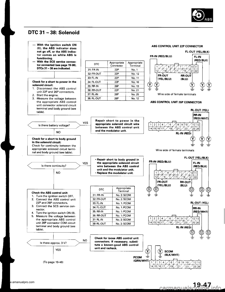
DTC 31 - 38: Solenoid
ABS CONTROL UNIT 22P CONNECTOR
Wire sade of female terminals
Wire side of female terminals
ABS CONTROL UNIT 26P CONNECTOR
FL.OUT IYEL/8LKI
DTCAppropraateConnectorTerminal
31: FR'lN22PNo. 1
32: FR OUT22PNo. 12
33: FL lN22PNo. 11
34: FL OUT22PNo.10
35:RR-lN26PNo.13
36: RR-OUT22PNo.21
37: RLIN26PNo.25
38: RL-OUT26PNo. 12
RL.OUT {YELI
FL.OUT IYEL/BLKI
DTCAppropriateTerminal
31: FR lNNo. 2i SCOM
32: FR-OUTNo. 2: SCOM
33: FLINNo.1:PCOM
34: FL-OUTNo. 1:PCOM
35:RRINNo. 1: PCON4
36: RR-OUTNo. 1: PCON4
37rRL-lNNo. 2: SCOM
3a: RL-OUTNo. 2: SCOM
RL.OUT {YELI
- With the ignition switch ON{lD, tho ABS indicator doesnot go off, or the ABS indic.-lor comes on whil6 ABS istunctioning.- With th€ SCS service connoc-tor connoctcd {sce page 1$381,DTCa 31 - 38 ars indicatsd.
Check for a 3hori to power in th€solenoid ci.cuit:1. Disconnect the ABS controluntr tlr ano zbr connectors_2. Start the engine.3. Measure the voltage betweenthe appropriate ABS controlunit connector solenoid circuitterminal and body ground (see
table).
R€pair short to power in theapprop.iato solenoid circuit wirebetwe€n the ABS control unitand the modulator unh.
ls there baRery voltage?
Chock for a short to body groundin the sol€noid circuit:Check for continuity between theappropriate solenoid circuit termi-naland body ground (see table).
. Ropair short to body ground inthe appropriato solenoid circuitwire betwoon the ABS controlunit and the modulator unit.. Replace the modulator unit.
ls there continuity?
Check the ABS control unit:1. Turn the ignition switch OFF.2. Connect the ABS control unit22P and 26P connectors.3. Connect the SCS service con-nector.4. Turn the ignition switch ON (ll).5, Measure the voltage betweenthe appropriate ABS controlunit 26P connector COM circuitterminal and body ground (seetable).
Check tor loose ABS control unitconnectors. ll nece$ary, substi-tut€ a known-good ABS controlunit and recheck.
ls there approx. 3 V7
PCOM
(To page l9-48){GRN/WHTI
19-47
www.emanualpro.com
Page 971 of 1395
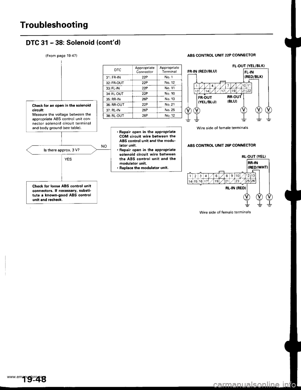
Troubleshooting
DTC 31 - 38: Solenoid (cont'dl
A8S CONTROL UNIT 22P CONNECTOR
Wire side of female terminals
ABS CONTROL UNIT 26P CONNECTOR
Check for an open in the solenoidcircuit:Measure the voltage between theappropriate ABS control unit connector solenoid circuit terminaland body ground {seetable).. Repair open in the appropriateCOM circuit wire botween theABS control unit and th€ modu-lator unit.. Repair open in the appropriatesolenoid circuit wire betw€onlhe ABS control unit and themodulator unit.. Replace ih€ modulator unit.
ls there approx. 3 V?
Check for loos€ ABS control unilconn€ctors. lf nece$ary, substi-tute a known-good ABS controlunit and rechock.
FL.OUT IYEL/BLK}DTCConnector
31: FRIN22PNo. 1
32: FR-OUT22PNo.12
33: FL-IN22PNo.11
34: FL OUT22PNo.10
35:RRIN26PNo.13
36:RR-OUT22PNo.21
37:RLIN26PNo. 25
38:RL-OUTNo. 12
RI-.OUT {YEL)
Wire side of female termanals
19-48
www.emanualpro.com