Circuit HONDA CR-V 1999 RD1-RD3 / 1.G Owners Manual
[x] Cancel search | Manufacturer: HONDA, Model Year: 1999, Model line: CR-V, Model: HONDA CR-V 1999 RD1-RD3 / 1.GPages: 1395, PDF Size: 35.62 MB
Page 621 of 1395
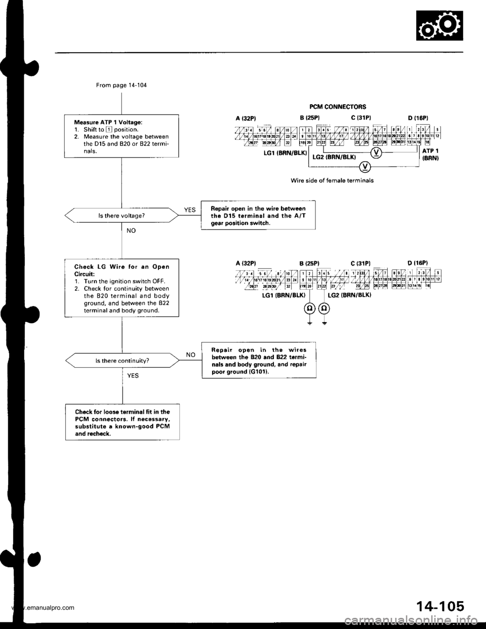
From page 14-104
Measure ATP 1 Voliag€:1. Shift to E position.2, Measure the voltage betweenthe D15 and 820 or B22 termi-nals.
Repair open in the wire betweenthe D15 terminal and the A/Tgear poaition switch.
Check LG Wire tor an OpenCircuit:'1. Turn the ignition switch OFF.2. Check lor continuity betweenthe 820 terminal and bodyground, and between the 822terminal and body ground.
Repair open in th. wiresbetween the B20 and 822 tarmi-nals and body ground. and repairpoor ground {G101).
ls there continuity?
Check tor loose terminaltit in thePCM connectors. lf n6cassary,substitute d known-good PCMand recheck.
B t25Pl
FCM CONNECTORS
c t3lPtD tl6Pl
LGl IBRN/BLKI
LGl (BRN/BLKI
Wire side of female terminals
A (32P1B (2sP)c (31P|
14-105
www.emanualpro.com
Page 623 of 1395
![HONDA CR-V 1999 RD1-RD3 / 1.G Owners Manual
A l32Pl
From page 14-106PCM CONNECTORS
B (25P1 C (31
LGl IERN/BLKILG2 {BRN/BLK)
Wire side of female terminals
LGl IBRN/BLK}LG2 (BRN/BLK}
SHIFT CONTROI SOLENOIDVALVE A/B ASSEMBLY CONNECTOR
IiiE-]
"*ot HONDA CR-V 1999 RD1-RD3 / 1.G Owners Manual
A l32Pl
From page 14-106PCM CONNECTORS
B (25P1 C (31
LGl IERN/BLKILG2 {BRN/BLK)
Wire side of female terminals
LGl IBRN/BLK}LG2 (BRN/BLK}
SHIFT CONTROI SOLENOIDVALVE A/B ASSEMBLY CONNECTOR
IiiE-]
"*ot](/img/13/5778/w960_5778-622.png)
A l32Pl
From page 14-106PCM CONNECTORS
B (25P1 C (31
LGl IERN/BLKILG2 {BRN/BLK)
Wire side of female terminals
LGl IBRN/BLK}LG2 (BRN/BLK}
SHIFT CONTROI SOLENOIDVALVE A/B ASSEMBLY CONNECTOR
IiiE-]
"*otrau/"aalF
I
Termanal side of male terminals
(cont'd)
14-107
c (31P)D {16P)
Check for continuity between the820 terminal and body ground.
and between the 822 terminaland body ground.
Ropair open in the wir.s betweonthe 820 and 822 terminal3 andground (G1011.
Check Shilt Control SolenoidValve A for . Short Circuit:1. Disconnect the 2P connectorfrom the shift control solenoidvalve !y'B assembly.2. Check tor continuity betweenthe D7 and B2O ot 822 tetmi-nals.
Repair short to ground in the wirebe{we€n the D7 terminal and the3hift control solonoid valvo A.ls there continuity?
Measure Shift Control SolenoidValve A Resistance at iheSolenoid Connector:Measure the resistance betweenthe No. I terminal of the shiftcontrol solenoid va lve A/Bassembly connector and bodygrou nd,
Replace the shrft control solenoidvalve A/B assembly.ls the resistance 12 25 Q?
Check for op.n in the wirebetwoon tho D7 terminal and theshift control solenoid valve A.
www.emanualpro.com
Page 626 of 1395
Electrical Troubleshooting ('98 - 00 Models)
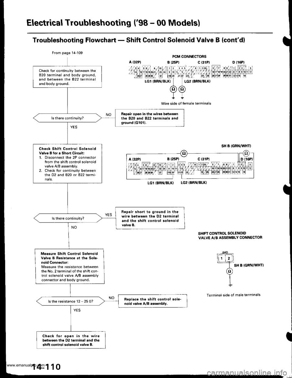
Troubleshooting Flowchart - Shift Control Solenoid Valve B {cont'd)
PCM CONNECTORS
a {25P) C t31
I
Wire side of l6male terminals
LG1 IBRN/BLKILG2IBRN/BLKI
SHIFT CONTROL SOLENOIDVALVE A/B ASSEMBLY CONNECTOR
lF-E]
I SH B IGRN/WHTI
(ol
YII
Terminal side of male terminals
From page 14-109
Check for continuity between the820 terminal and body ground,
and between the 822 terminaland body ground.
Repair open in the wire! b€twoenth6 B20 and 822 terminals andground lG101l.
Check Shilt Control SolenoidValve B for a Sho.t Circuit:1, Disconnect the 2P connectorfrom the shift control solenoidvalve !VB assembly.2. Check tor continuity betweenthe D2 and B2O o( 822 tetmi-nals,
Repair short to ground in thewir€ b€twe6n th€ D2 terminaland the shift control solenoidvalve B.
Measu.e Shift Control SolenoidValve B Rasistance at tha Solo-noid Connector:Measure the resistance betweenthe No. 2 terminal of the shift control solenoid valve NB assemblvconnector and body ground.
ReDlac. the shift control sole-noid valve A/B r$embly.ls the resistance 12 25 O?
Check for oDen in the wireb€twoen ths D2 torminal and theshift control 3olenoid valve 8.
A (32P1c 13lPlD tl6Pl
a t32Ptc {31P1
14-110
www.emanualpro.com
Page 629 of 1395
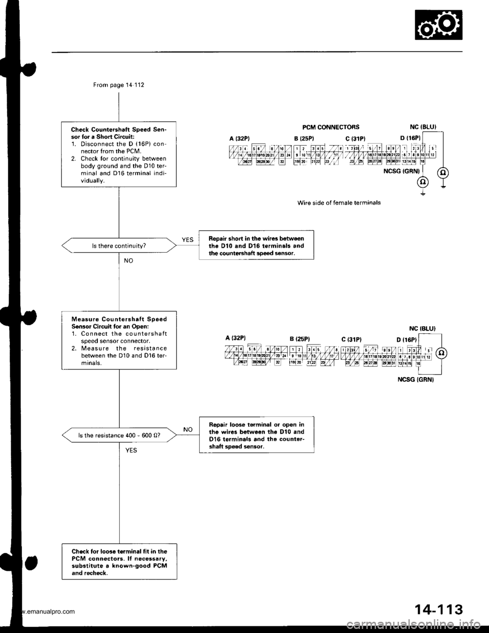
Check Countershaft Speed Sen-sor for a Short Circuit:'1. Disconnect the D (16P) connector from the PCM.2. Check lor continuity betweenbody ground and the D10 ter-minal and Dl6 terminal indi-vidually.
Repair short in the wire3 botweonthe Dl0 and D16 terminals andthe countershaft 3De€d sensor.
Measure Countershatt SpeedS6n3or Circuit to. an Open:1, Co n nect the countershaftspeeo sensor connector,2. Measu re the resistancebetween the D10 and D16 ter-mrnals,
Repair loose terminal or open inthe wiies between the D10 andO16 terminals and th. countet-shaft sD€ed sensor.
ls the resistance 400 - 600 0?
Check tor loos. terminal fit in thePCM conn€ctoas. It necessary,substitute a known-good PCMand recheck.
From page 14'112
A t32PlB (25P1
a l32PlB (25P1
PCM CONNECTORS
Wire side ol female terminals
NC IBLUI
D {16P1
NCSG IGRNI
c l31P)
ial, tu]g
c (31PI
NCSG IGRN}
14-113
www.emanualpro.com
Page 630 of 1395
Electrical Troubleshooting ('98 - 00 Modelsl
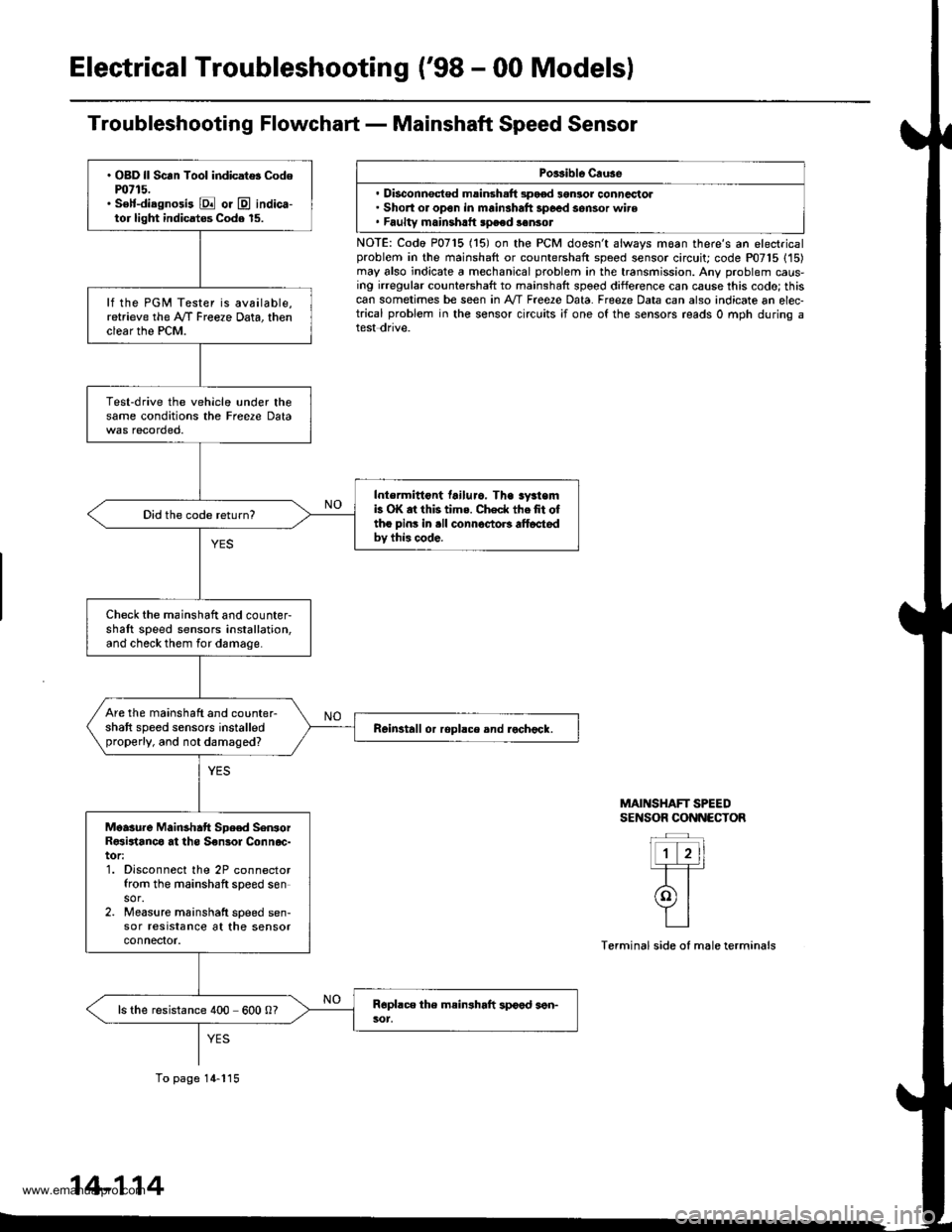
Troubleshooting Flowchart - Mainshaft Speed Sensor
Porsible Cruse
. Disconnsct€d msinsh.ft 3pood 3gnlor conncctol. Short or open in mainshaft 3poed sensor wire. Faultv mainshrtt speed sonsot
NOTE: Codo P0715 (15) on the PCM doesn't always moan there's an electricalproblem in the mainshaft or countershaft speed sensor circuit; code P07'15 (15)may also indicate a mechanical problem in the transmission. Any problem caus-ing irregular countershaft to mainshaft spoed difference can cause this codo; thiscan sometimes be seen in A'/T Free2e Data. Freeze Data can also indicate an elec-trical problem in the sensor circuits ;f one of the sensors reads 0 mph during atest dnve.
MAINSHAFT SPEEDSENSOR CONNECTOR
Terminal side of male terminals
. OBD ll Scan Tool indicat$ Codem715.. S€lf-diagnosi3 E or @ indica-tor light indicatos Code 15.
lf the PGM Tester is available,retrieve the A/f Freeze Data, thenclear the PCM.
Test-drive the vehicle under thesame conditions the Freere Data
Intermittont tailuro. Tha sy3temb OK at this tims. Check thefit oftho pins in .ll connoctoB alt6ctedbv this code.
Did the code return?
Check the mainshaft and counter-shaft speed sensors installation,and check them for damage.
Are the mainshaft and counter-shaft speed sensors installedproperly, and not damaged?Reinstall or ropllce and rochock.
Moasure Mainshatt Spe€d SenrorR€sirtanco at ths S€nsol Connoc-tor:1. Disconnect the 2P connectorfrom the mainshaft speed sensor.2. Measure mainshatt speed sen-sor resrstance at the sensorconnefior.
ls the resistance 400 600 0?
To page 14-115
14-114
www.emanualpro.com
Page 631 of 1395
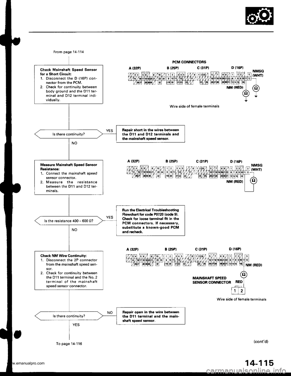
A {32P}
From page 14-114
Check Mainshaft Speed Sensorfor a Short Circuit:1. Disconnect the D (16P) con-nector trom the PCM.2- Ch€ck tor continuity betweenbody ground and the D11 ter-minal and Dl2 terminal individually.
ReDair short in tho wiros botwe€nth€ Dl1 and D12 torminal3.ndtho main3haft 3Doed aonlor.
Moasure Mainshaft Sp6€d SonsorRosi3tancei1. Connect the mainshaft speedsensor conn6ctor.2. Measure the resistancebetween the Dl1 and D12 ter-mrnals,
Run the Eloctric€l TroubldhootingFlowdrrrt for co& F0720 (codo 91.Chock lor loo3o torminrl fit in thePCM connectors. It necos3ary,substitute r known-good PCMand r€ch€ck.
ls the resistance 400 - 600 0?
Chock NM Wire Continuity:1. Disconnect the 2P connectortrom the m6inshaft speed sen-
2. Check for continuity betweenthe D11 terminal and the No. 2terminal of the mainshaftspeeo sensor connector,
Rcpair opon in tho wire betw.enth6 Dll tarminal and the main-shaft lpood sonsor.
To page'14-1'16
PCM CONNECTORS
c t3lPl
wire side ol female terminals
B l25Pt
D t16PtNMSG-'lTZ lit4'l Fl l'1til FTil ,'l unrv v v v v l.t1lLtLt?!/]|,1tut larrlrllllpr=rtavtq tptntat EElt [1!]t! pl
NM (RCD| (O)
(o)Y
Y=
c {31P1--_|--1\‰1,/ s/1 st/v,1zzfififinffiiFrF/l,6t FFF| LrLrEllNM {REDI
MAINSHAFT SPEEOSENSOR CONNECTOR
Wire side of temale terminals
(cont'd)
14-115
www.emanualpro.com
Page 634 of 1395
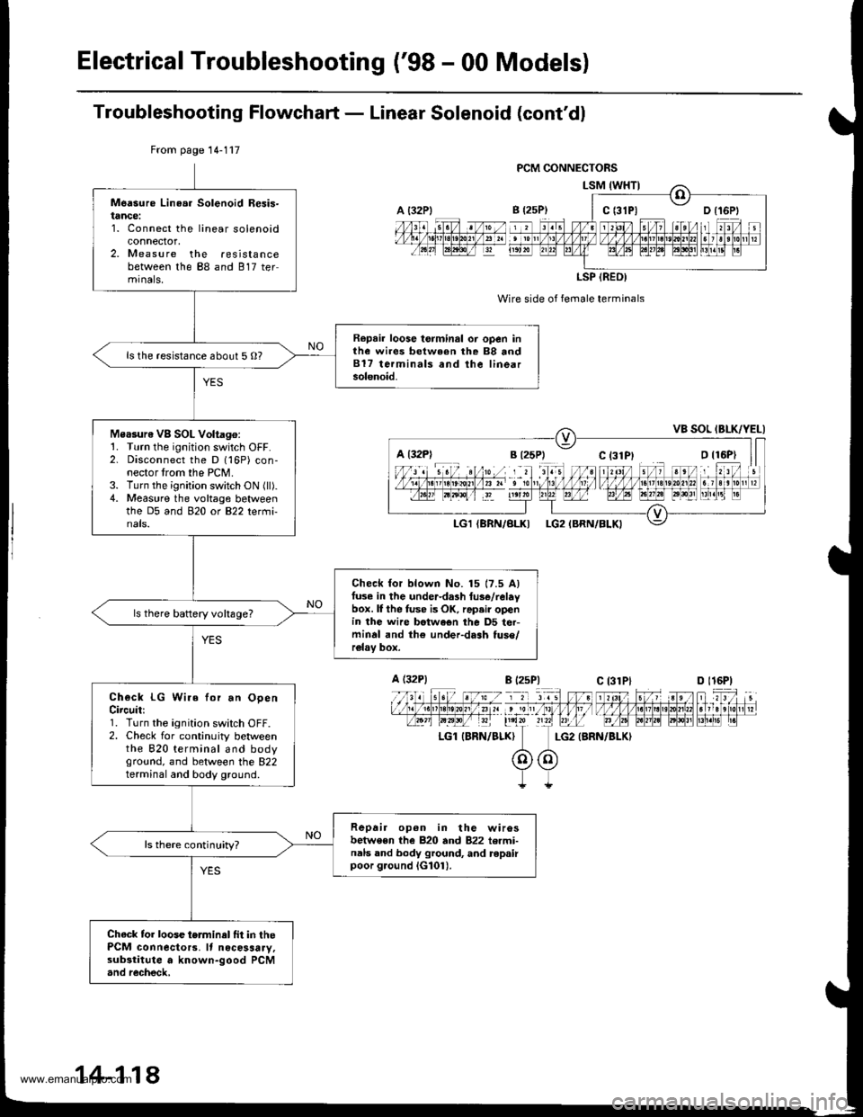
ElectricalTroubleshooting ('98 - 00 Models)
Troubleshooting Flowchaft - Linear Solenoid (cont'dl
Wire side of female terminals
LG2 {BRN/BLKI
From page 14-117
Measure Linea. Solenoid Resis-tance:1. Connect the linear solenoidconnector,2. Measure the resistancebetween the 88 and 817 termrnals,
Repair loose torminal oi open inthe wires between rhe 88 and817 terminals and the linearsolenoid.
ls the resistance about 5 O?
Measure VB SOL Voltago:1. Turn the ignition switch OFF.2. Disconnect the D 116P) con-nector trom the PCM.3. Turn the ignition switch ON (ll).4. Measure the voltage betweenthe D5 and 920 ot B22 tetmi-nals.
Check for blown No. 15 17.5 Alfuse in the under-da3h tus€/relaybox. lI the fuse is OK, rap.ir openin the wire betwe€n the D5 ter-minal and th€ under-dash tuso/relav box.
ls there baftery voltsge?
Check LG Wire for.n OpenCircuit:1. Turn the ignition switch OFF.2. Check for continuity betweenthe 820 terminal and bodyground, and between the 822terminal and body ground.
Repair op6n in the wirosbetwe€n the 820 and 822 termi-nals and body ground, and repairpoor g.ound iG101).
ls there continuity?
Chack tor loose terminel fit in thePCM connecto13. It nocosaary,substitute a known-good PCM.nd recheck,
a t32Plc t3lPl
LSP (REO)
a l32Pl
A (32P1
LGl IBRN/BLK}
B l2sP)c 13lPlD l16P)
14-118
www.emanualpro.com
Page 639 of 1395
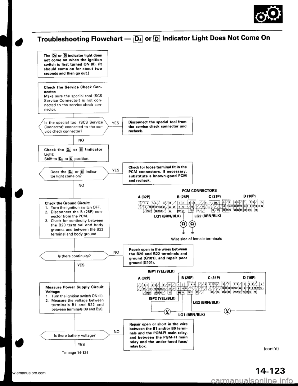
Troubleshooting Flowchart - Df or @ Indicator Light Does Not Come On
PCM CONNECTORS
B t2sPl c (31D (16P)
l*f4tr 8-
f - -- -6 3 rol ,: irr t lrpri$fe?0?r/a)1 e 'oI 13 11/ / l//|rrr I , ltelx ?r2? r,/i-T_LG1 {8RN/BI-KI I LG2 (BRN/BL()I
@@I++
Wire side of lemale terminals
(cont'd)
14-123
The E or El indicator light doe3not cofie on when the ignitaon
switch is first turned ON {ll). {ltshould como on for about two
s.cond3 and ihen go out.l
Check ths Service Check Con-
neclor:Make sure the special tool (SCS
Service Connector) is not connected to the service check connector.
Disconnecl the special lool lromtha service check connoctor andrecheck.
ls the special tool (SCS ServiceConnector) connected to the ser_vice check connector?
check the E or E Indicator
Ught:Shift to E or E position.
Check for loo3e t6lminal tit in thePCM connectors. lf necessary.substitute a known-good PCMand recheck.
Does the E or P indica-tor light come on?
Check the Gtound Circuil:1. Turn the ignition switch OFF.2. Disconnect the B (25P) con-nector from the PCM.3. Check for continuitY betweenthe 820 terminal and bodyground, and between the 822
terminal and body ground.
Repair open in the wires betweenthe 820 and 822 terminals andground {G1011, and r€Pair Poorground (G101).
ls there continuity?
Measure Power Supply CircuitVoltage:1. Turn the ignition switch ON 1ll).2. Measure the voltage betweenterminals B1 and 822 andbetween terminals Bg and 820.
Repair open or short in tho wi.ebetween the 81 and/or Bg tormi-nals and the PGM-FI main r€lay,.nd between tho PGM-FI mainrelay and the under-hood tuse/relay box.
ls there battery voltage?
A l32Plc (31P)
c (31P)
YES
To page 14-124
www.emanualpro.com
Page 640 of 1395
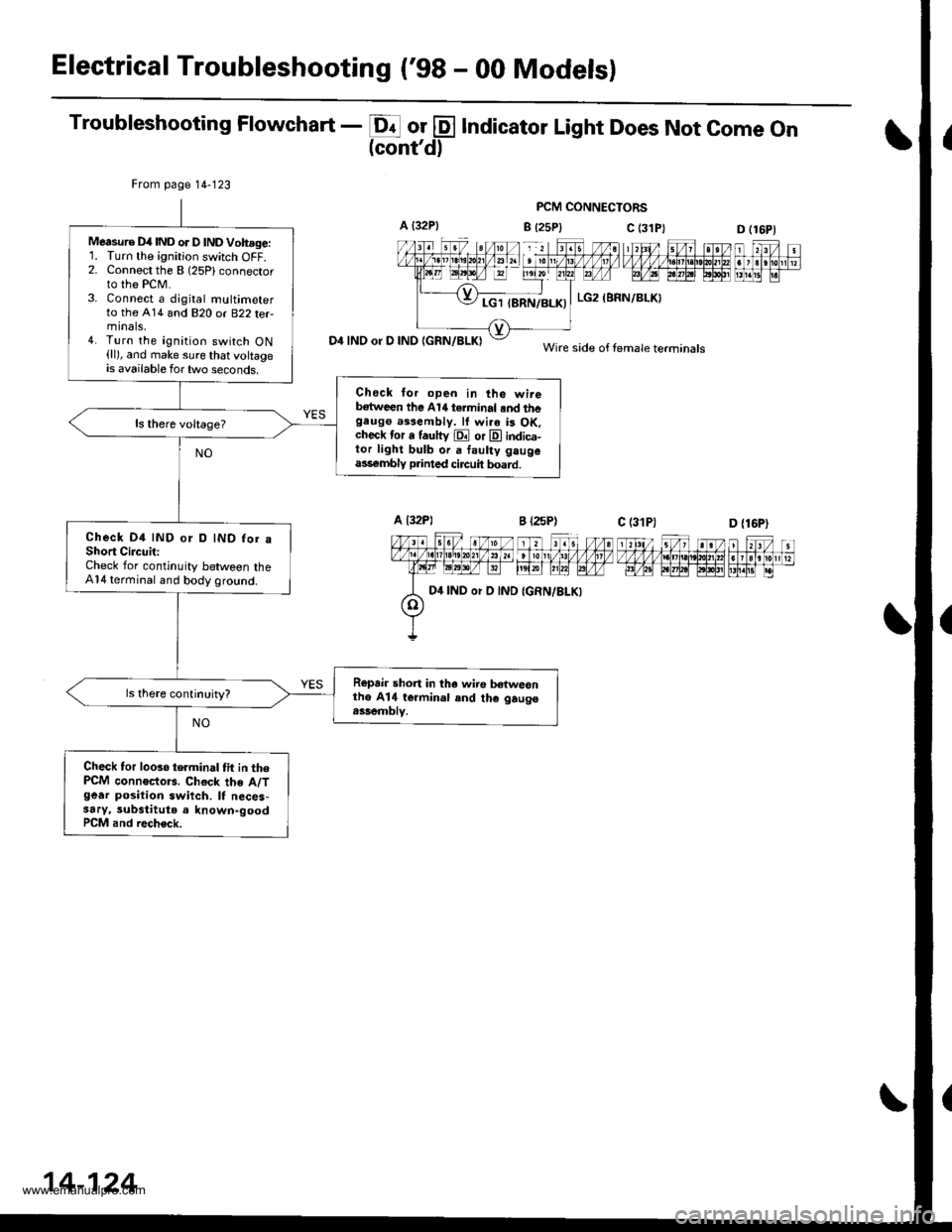
Electrical Troubleshooting ('98 - 00 Modelsl
Troubleshooting Flowchart - E or @ Indicator Light Does Not come on(cont'd)
PCM CONNECTORS
B {25P} C (3D (16P1
n f,-ff nt f,Fjrti.trnnmflnr
D4 INO or D IND IGRN/BLKI
From page 14-123
Measure D4IND or D lNDVoh.ge:'L Turn the ignition switch OFF.2. Connect the B (25Plconnector
to the PCM.3. Connect a djgital multimeterto the A14 and 820 or B22 terminals,4. Turn the ignition switch ON(ll), and make sure that voltageis available for two seconds.
Check lor open in the wireb€tween the Al/t terminal .nd thegeugo a$eftbly. lf wi.a is OK.check tor a fautty E or E indica-tor light bulb or a faulty gaugeass€mbly p.inted circuit board.
Check D4 IND or D IND for aShort CircuitiCheck for continuity between theA14 terminal and body ground.
Ropair short in tha wiro b€twesnthe A14 termin.l and th€ gaugo.ssemblv.
Check tor looso telminal tit in thePCM connoctors. Chock the A/Tgear position swiich. It neces-3ary, substitute a known-goodPCM and rech€ck.
c (31P)
LG2 (BRN/BLKI
Wire side of female terminals
D {16P)
D4 IND or D IND
14-124
www.emanualpro.com
Page 642 of 1395
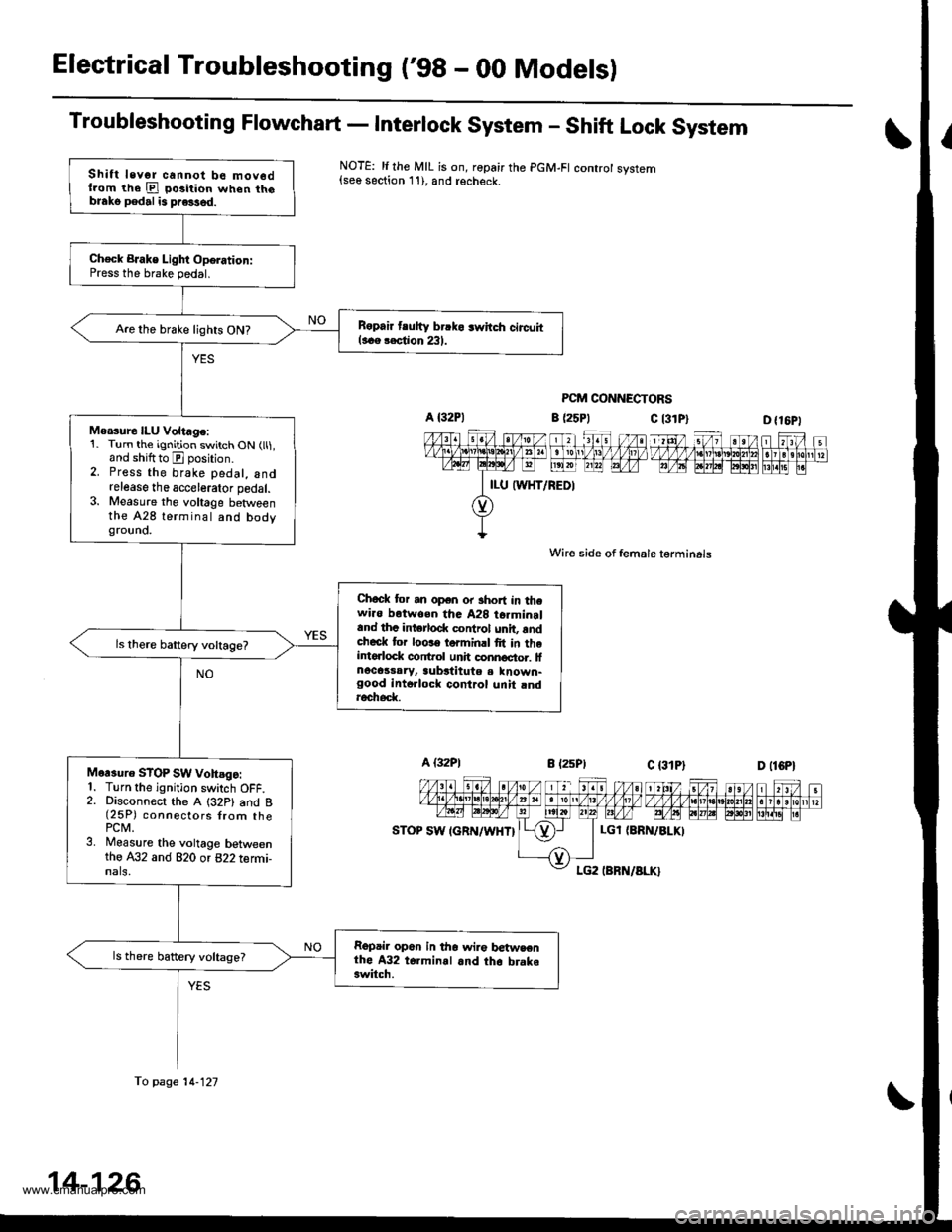
Electrical Troubleshooting ('98 - 00 Modelsl
Troubleshooting Flowchart - Interlock System - Shift Lock System
NOTE: li the MIL is on, ropair the PGM-FI controt system{see section 11), and recheck.
PCM CONNECTORS
c l3lPl
Wire side of female lerminals
c t3lPt
D {16P1
1 tttt/ 5t/ 1 a t /tlt 1 t\/t ,/ VVV tl t ttj,r\1e\10l211n . I 3 rholr1 t?m@-@Effilil"
D (lCPl
| 2ttt/ ;t /n) ).tt)/ 1 21:/ tvvvvv nnvl.lnl2
I r r ero
12wE gp]P] polr EI!l!!i r.
a (25P1
LGl {8RN/ALKI
Shift levor cannot be mov6dllom the E po3ition when th6blako pedal is pre3sed.
Ch€ck BJake Light Oporation:Press the brake pedal.
B6pair tlutty brrko 3whch circuitl..e rection 231.Are the brake lights ON?
Me.sure ILU Voltage:1. Turn the ignition switch ON (ll1,and shiftto E position.2. Press the brake pedal, andrelease the accelerator pedal.3. Measure the voltage betweenthe A28 terminal and bodygrouno.
Chock tor an open or short in thewi.o botwoen tha A28 t6rminrland thc intorlod( control unit, rndcheck tor loose torminrl fit in theintorlock conftol unh connoctor. lfnocassaryr aubstitute a known-good intollock control unit rndroch6d(
Mor3uro STOP SW vohsgo:1. Turn the ignition switch OFF.2. Disconnect the A (32P1 and B(25P) connectors {rom thePCM.3. Measure the voltage betweenthe A32 and 820 or 822 termi-nals,
Repair op6n in tho wir€ betwsenthe A32 t6.minal and th6 brake3witch.
ls there battery voltage?
fo page 14-121
14-126
www.emanualpro.com