trans HONDA CR-V 1999 RD1-RD3 / 1.G Workshop Manual
[x] Cancel search | Manufacturer: HONDA, Model Year: 1999, Model line: CR-V, Model: HONDA CR-V 1999 RD1-RD3 / 1.GPages: 1395, PDF Size: 35.62 MB
Page 699 of 1395
oatl,6
@!.,
ao6l
@o@@@@@o@@@)@@@@@@@@@@)
@@@@)@@@@@@@
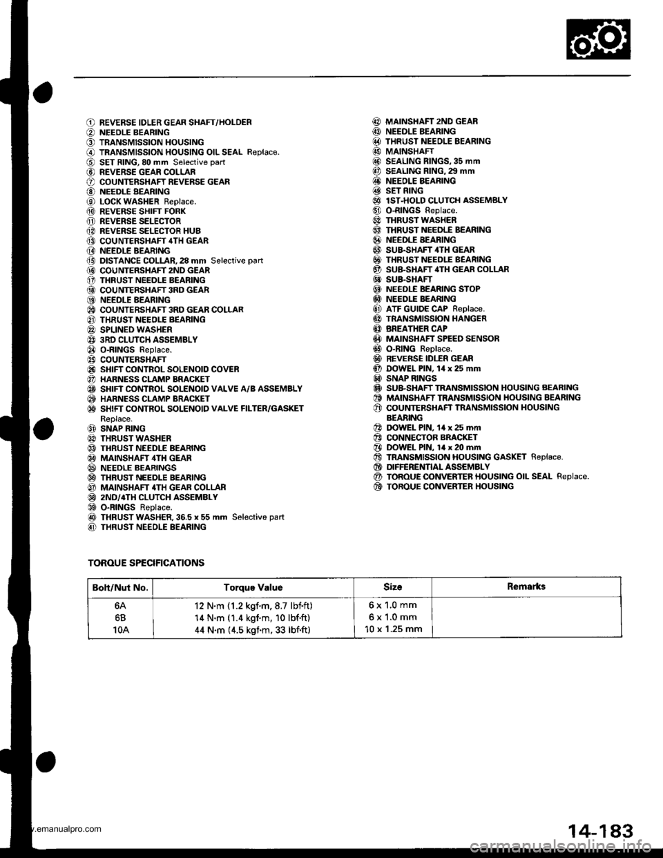
REVERSE IDLER GEAR SHAFT,/HOLDERNEEOLE BEARINGTRANSMISSION HOUSINGTRANSMISSION HOUSING OIL SEAL R€place.SET RING,80 mm Selective part
REVERSE GEAR COLLARCOUNTERSHAFT REVERSE GEARNEEDLE BEARINGLOCK WASHER Replace.REVERSE SHIFT FORKREVERSE SELECTORREVERSE SELECTOR HUBCOUNTERSHAFT 4TH GEARNEEDLE BEARINGDISTANCE COLLAR,28 mm Selective pan
COUNTERSIIAFT 2ND GEARTHRUST NEEDLE BEARINGCOUNTERSHAFT 3RD GEARNEEDLE AEARINGCOUNTERSHAFT 3RD GEAR COLLARTHRUST NEEOLE BEARINGSPLINEO WASHER3RD CLUTCH ASSEMBLYO-RINGS Replace.COUNTERSHAFTSHIFT CONTROL SOLENOID COVERHARNESS CLAMP BRACKETSHIFT CONTROL SOLENOID VALVE A/B ASSEMBLYHARNESS CLAMP BRACKETSHIFT CONTROL SOLENOID VALVE FILTER/GASKETReplace.SNAP RINGTHRUST WASHERTHRUST NEEDLE BEARINGMAINSHAF ,ITH GEARNEEDLE BEARINGSTHRUST NEEDLE BEARINGMAINSHAFT 4TH GEAR COLLAR2ND/4TH CLUTCH ASSEMBLYO-RINGS ReDlace.THRUST WASHER,36.5 x 55 mm Selective part
THRUST NEEDLE BEARING
MAINSHAFT 2ND GEARNEEDLE BEARINGTHRUST NEEOLE BEARINGMAINSHAFTSEALING RINGS,35 mmSEALING RING. 29 mmNEEDLE BEARINGSET RINGlST-HOLD CLUTCH ASSEMSLYO-RINGS Replace.THRUST WASHERTHRUST NEEDLE BEARINGNEEDLE BEARINGSUB.SHAFT 4TH GEARTHRUST NEEDLE BEARINGSU&SHAFT,ITH GEAR COLLARSUB.SHAFTNEEDLE BEARING STOPNEEDLE BEARINGATF GUIDE CAP Replace.TRANSMISSION HANGERBREATHER CAPMAINSHAFT SPEED SENSORO-RING Reolace.REVERSE IDI.fR GEARDOWEL PlN, lil x 25 mmSNAP RINGSSU&SHAFT TRANSMISSION HOUSING AEARINGMAINSHAFT TRANSMISSION HOUSING BEARINGCOUNTERSHAFT TNANSMISSION HOUSINGBEABINGDOWEL PlN, 14 x 25 mrnCONNECTOR BRACKETDOWEL PlN, 14 x 20 mmTRANSMISSION HOUSING GASKET Replace.DIFFERENTIAL ASSEMBLYTOROUE OONVERTER HOUSING OIL SEAL Replace.TOROUE CONVERTER HOUSING
@@@@@@@@@@@@@@@@@@@@@@@)@@@@@@@
@@@@@@@
TOROUE SPECIFICATIONS
Boli/Nut No.Torque ValueSizeRemarks
6B
10A
12 N.m (1.2 kgf.m,8.7 lbf.ft)'14 N.m (1.4 kgim, 10 lbf'ft)
44 N.m (4.5 kgim, 33 lbf.ft)
6x 1.0 mm
6x1.0mm
10 x '1.25 mm
14-1A3
www.emanualpro.com
Page 702 of 1395
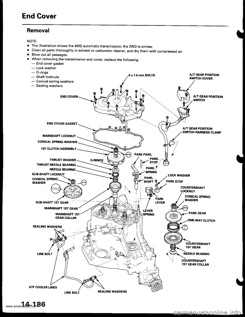
End Cover
Removal
NOTE:
o The illustration shows the 4WD automatic transmission; the 2WD is similar.. cleanall parts thoroughly in solvent or carburetor cleaner, and drythem with compressed air.. Blow out all passages.
. When removing the transmission end cover, replace the following:- End cover gasket- Lock washer- O-rings- Shaft locknuts- Conical spring washers- Sealing washers
END COVER GASKET
MAINSHAFT LOCKNUT
CONICAL SPRING WASHER
6 x 1 .0 rhm EOLTS
PARK PAWL
A/T GEAR POSMONSwlTCH COVER
NEEDI.T BEARING
SUB.SHAFT LOCKNUT
CONICAL SPRINGWASHER
LINE AOLT
ATF COOI.f B LINES
14-186
PAwL 7// Locx wASHER
'sHAFr 9/ ?ARK srop
o-- Ay' couNTERsHAFr
G-€ LocKNUr!€ / ..t,"o, "oo
A/T GEAR POSMONSW|TCH HARNESS CLAMP
CONICAL SPRINGWASHCR
A/T GEAR POSITION
PARK GEAR
Y CLUTCH
lST GEAR
NEEDLE BEARING
1ST CLUTCH ASSEMBLY
THRUST WASHER
THRUST NEEDLE AEARING
O.RINGS
\\
SUB.SHAFT 1ST GEAR
MAINSHAF? 'ST GEAR
MAINSHAFT 1STGEAR COLLAR
SEALING WASHERS
!€'-l
I"EVERSPRING
COUNTERSHAFTlST GEAR COLLAR
PAWL
lt1/ sroe
Y plwl f
L/'SPRING
LOCKNUT
LINE BOLTSEALING WASHERS
www.emanualpro.com
Page 703 of 1395
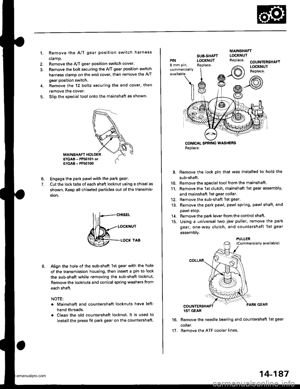
1. Remove the A/T gear position switch harness
cramp.
Remove the y'VT gear position switch cover.
Remove the bolt securing the ly'T gear position switch
harness clamp on the end cover, then remove the A/T
gear position switch.
Remove the 12 bolts securing the end cover. then
remove the cover.
Slip the special tool onto the mainshaft as shown.
6. Engage the park pawl with the park gear.
7. Cut the locktabs of each shaft locknut using a chisel as
shown. Keep all chiseled particles out of the transmis-
ston.
M=tt"
Align the hole of the sub-shaft 1st gear with the hole
of the transmission housing. then insert a pin to lock
the sub-shaft while removing the sub-shaft locknut.
Remove the locknuts and conical spring washers from
each shaft.
NOTE:
Mainshaft and countershaft locknuts have left-
hand threads.
Clean the old countershaft locknut. lt is used to
install the press fit park gear on the countershaft.
MAINSHAFT
PIN8 mm pin,
commercially
SUB-SHAFTLOCKNUTReplace.COUNTERSHAFTLOCKNUTReplace.
CONICAL SPNING WASHERSReplace.
9. Remove the lock pin that was installed to hold the
sub-shaft.
10. Remove the special tool from the mainshaft.
11. Remove the 1st clutch, mainshaft 1st gear assembly,
and mainshaft 1st gear collar.'12. Remove the sub-shaft 1st gear.
13. Remove the park pawl, pawl spring, pawl shaft. and
pawl stoP.
14. Remove the park lever from the control shaft.
15. Using a universal two jaw puller, remove the park
gear, one-way clutch, and countershaft 1st geal
assemblv.
{Commercially available)
1SY GEAR
Remove the needle bearing and countershaft 1st gear
co ar.
Remove the ATF cooler lines,
LOCKNUTReplace.
2\
Irot)
PULLER
11.
14-187
www.emanualpro.com
Page 704 of 1395
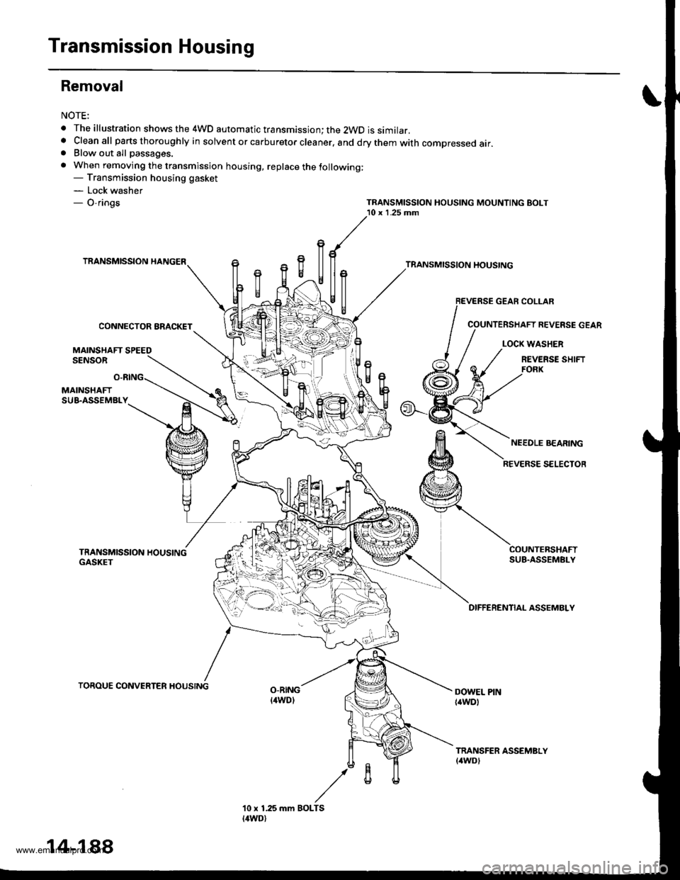
Transmission Housing
Removal
NOTE:
. The illustration shows the 4WD automatic transmission; the 2WD is similar,. Cleanall parts thoroughly in solvent or carburetor cleaner. and drythemwith compressed air.. Blow out all passages.
. When removing the transmission housing, replace the lollowing:- Transmission housing gasket- Lock washer- O-rings
TRANSMISSION HANGERTRANSMISSION HOUSING
REVERSE GEAN COLLAR
TRANSMISSION HOUSING MOUNTING EOLT
CONNECTOR BRACKET
MAINSHAFT SPEEDSENSOR
REVERSE GEAR
LOCK WASHER
REVERSE SHIFT
MAINSHAFTSUB.ASSEMBLY
TRANSMISSION HOUSINGGASKET
DIFFERENTIAL ASSEMBLY
TOROUE CONVERTER HOUSINGO-RINGt4wDl
TRANSFER ASSEMBLYt4wDt
10 x 1.25 mm
l4wo)
14-1 88
BOLTS
www.emanualpro.com
Page 705 of 1395
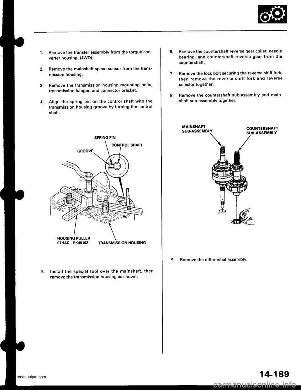
1.Remove the transfer assembly from the torque con-
verter housing. (4WD)
Remove the mainshaft speed sensor from the trans-
mission housing.
Remove the transmission housing mounting bolts,
transmission hanger, and connector bracket.
Align the spring pin on the control shaft with the
transmission housing groove by turning the control
shaft.
Install the special tool over the mainshaft. then
remove the transmission housing as shown.
4.
SPRING PIN
7.
Remove the countershaft reverse gear collar, needle
bearing, and countershaft revsrse gear from the
countershaft,
Remove the lock bolt securing tho reverse shift fork,
then remove the reverse shift fork and reverse
selector together.
Remove the countershaft sub-assemblv and main-
shaft sub-assembly together,
9. Remove the differential assembly.
8.
14-189
www.emanualpro.com
Page 706 of 1395
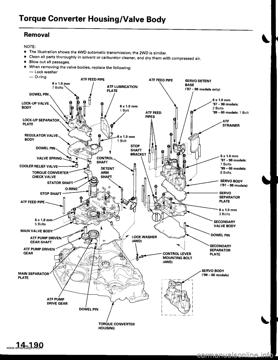
Torque Converter Housing/Valve Body
Removal
NOTE:
. The illustration shows the 4WD automatic transmission; the 2WD is similar.' cleanall parts thoroughry in sorvent or carburetor creaner, and drythem with compressed air.. Blow out all passages.
. When removing the valve bodies, replace the following:- Lock washer- O-ringATF FEED PIPESERVO DETENTBASE137 - 98 models only)
DOWEL PIN
LOCK.UP VALVEBOOY
6x1.0mm'97 - 98 models:2 Bolts'99 - 00 modeb: 1 Bolt
LOCK.UP SEPARAPLATE
REGULAIOR VALVEBOOY
ATFSTRAINER
DOWEL PIN
COOLER RELIEF VALVE
6x1.0mm37 - 98 models:7 Bolts'gg - 0O models:8 Bolts
SERVO BODY137 - 98 modelsl
SERVOSEPARATORPLATE
TOROUE CONVERTERCHECK VALVE
STATOR SHAFT
O.RING
5x1.0mfi3 Bolts
SECONDARYVALVE BODY
MAIN VALVE BODY
6x 1.05 Bolts
ATF PUMP ORIVENGEAR SHAFT
DOWEL PIN
ATF PUMP DRIVENGEAR
\
CONTROL LEVERMOUNTING BOLT{awD)
SECONDARYSEPARATORPLATE
14-190
www.emanualpro.com
Page 719 of 1395
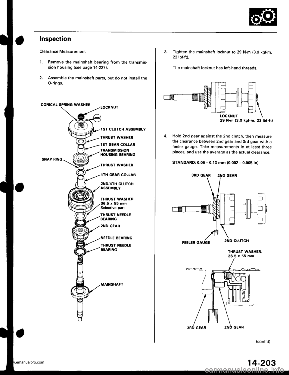
Inspection
Clearance Measurement
1. Remove the mainshaft bearing from the transmis-
sion housing lsee page 14-227l..
2. Assemble the mainshaft parts, but do not install the
O-rings,
CONICAL SPRING WASHER
SNAP RII{G
lST CLUTCH ASSEMELY
THRUST WASHER
1ST GEAB COLLAR
TRAI{SMISSIONHOUSIf{G BEARING
THRUST WASI{ER
2[{D/4TH CLUTCHASSEMALY
GEAR COLLAR
THRUST WASHER.5r55mmSelective part
THBUST IIEEDLEEEARII{G
2ND G€AR
EEARIt{G
TI{RUST NEEOLEBEARII{G
MAII{SHAFT
3. Tighten the mainshaft locknut to 29 N.m (3.0 kgf.m,
22 tbf.ft).
The mainshaft locknut has left-hand threads.
29 N.m (3.O kst.m, 22 lbt.frl
Hold 2nd gear against the 2nd clutch, then measure
the clearance between 2nd gear and 3rd gear with a
feeler gauge. Take measurements in at least threeplaces, and use the average as the actual clearance.
STANDARD: 0.05 - 0.13 mm (0.002 - 0.005 in)
FEELER GAUGC
THRUST WASHER.36.5 x 55 mm
(cont'd)
3RD GEAR 2'{D GEAR
14-203
www.emanualpro.com
Page 721 of 1395
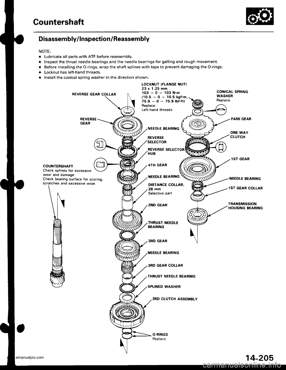
Countershaft
Disassembly/lnspection/Reassembly
NOTE:
. Lubricate all pans with ATF before reassembly.
.Inspectthethrustneedlebearingsandtheneedlebearingsforgallingandroughmov\
ement.
. Before installing the O-rings, wrap the shaft spllnes with tape to prevent damaging the O-rings.
. Locknut has left-hand threads.
. Install the conical spring washer in the direction shown.
R€VERSE GEAR
LOCKNUT IFLANGE NUTI23 x 1.25 mm103-0-103N.mCONICAL SPRINGWASHERReplace.t10.5 - 0 -
75.9 - 0 -
Replace.
10.5 kgl.m,75.9 lbt.lr)
Lelt.hand threads
COUNTERSHAFTCheck splines for excessivewear and damage.
REVERSE SELECTORHUB
4TH GEAR
NEEDLE EEARING
NEEOLE BEARING
REVERSESELECTOR
OISTANCE COLLAR.28 mmSelective part
2NO GEAR
lST GEAR
I{EEDLE BEARINGCheck bearing surface for scoring,scratches and excessive wear.lST GEAR COLLAR
TRANSn SSTONHOUSI G BEARING
3RD GEAR
NEEDLE BEARING
3RD GEAR COLLAR
THRUST NEEOLE BEARING
SPLINED WASHER
3RO CLUTCH ASS€MBLY
14-205
www.emanualpro.com
Page 723 of 1395
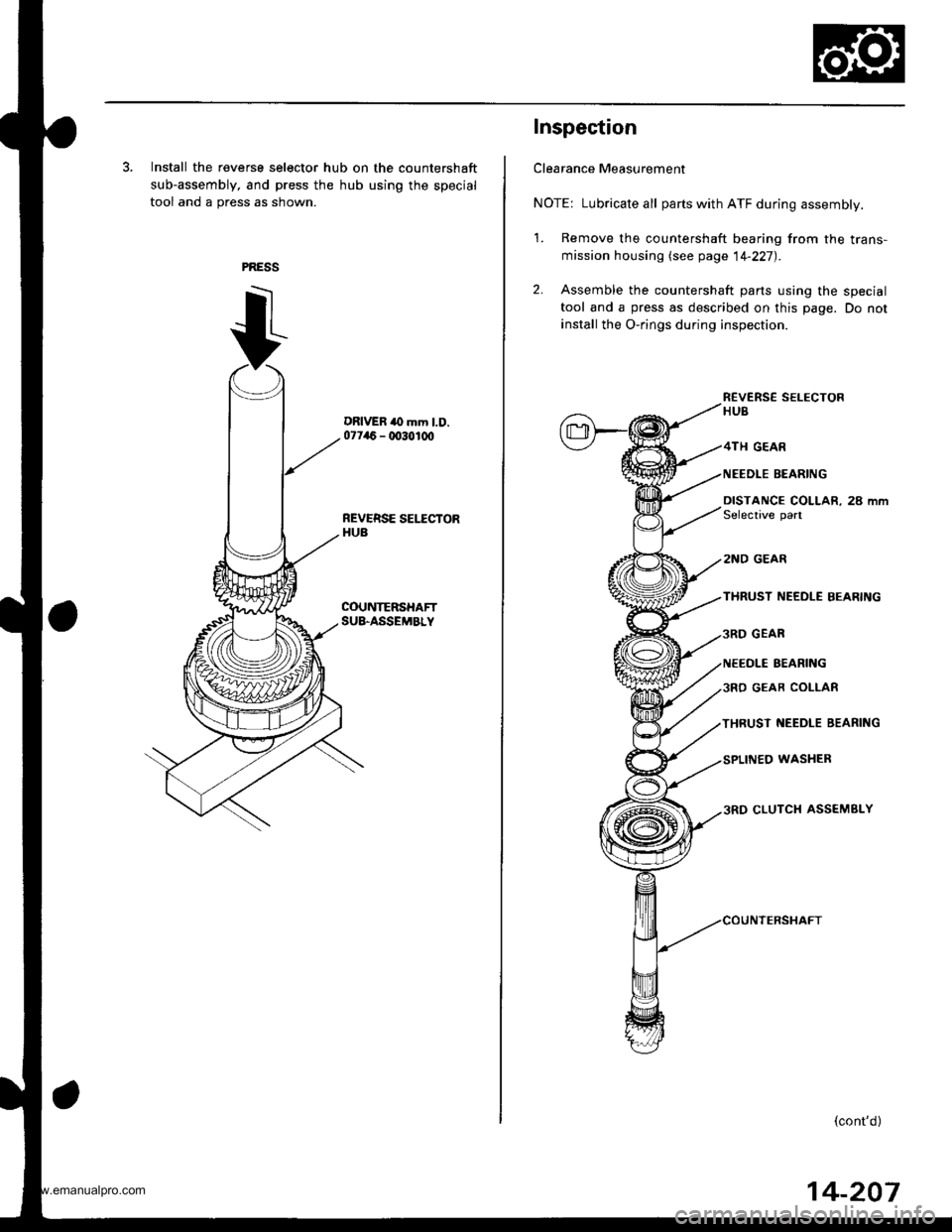
3. Install the reverse selector hub on the countershaft
sub-assembly, and press the hub using the special
tool and a press as shown.
DRIVER to mm l.D.07746 - 0030100
REVERSE SEI.ICTORHUB
COUNTERSHAFTSU&ASSEMBLY
Inspection
Clearance Measurement
NOTE: Lubricate all parts with ATF during assembly.
1. Remove the countershaft bearing from the trans-
mission housing lsee page 14-227).
2. Assemble the countershaft parts using the special
tool and a press as described on this page. Do not
install the O-rings during inspection.
R€VERS€ SELECTORHUB
GEAR
NEEDLE BEARING
DISTANCE COLLAR, 28 mmSelective part
2NO GEAR
THRUST NEEDLE BEARING
GEAR
NEEOLE BEARING
GEAR COLIAR
THRUST NEEDLE BEARING
WASHER
CLUTCH ASSEMBLY
(cont'd)
14-207
www.emanualpro.com
Page 724 of 1395
Countershaft
Inspection (cont'd)
3.
4.
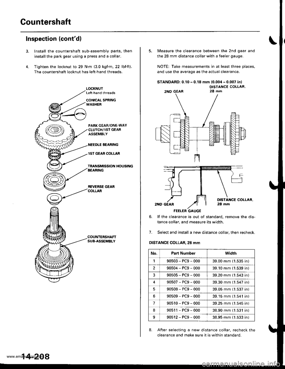
Install the countershaft sub-assembly parts, then
installthe park gear using a press and a collar.
Tighten the locknut to 29 N.m (3.0 kgf.m, 22 lbf.ft).
The countershaft locknut has left-hand threads.
LOCKNUTLe{t-hand threads
CONICAL SPRINGWASHER
PABK GEAR/ONE.WAYCLUTCH/1ST GEARASSEMBLY
NEEDLE BEANING
lST GEAR COLLAR
TRANSMISSION HOUSINGAEARING
REVERSE GEARCOLLAR
COUNTERSHAFTSUB.ASSEMBLY
14-208
5. Measure the clearance between the 2nd gear and
the 28 mm distance collar with a feeler gauge.
NOTE: Take measurements in at least three places,
and use the average as the actual clearance.
STANDARD: 0.10 - 0.18 mm (0.004 - 0.007 in)
OISTANCE COLLAR,28 mm
FEELER GAUGE
6. lf the clearance is out ot standard, remove the dis-
tance collar, and measure its width.
7. Select and install a new distance collar, then recheck.
DISTANCE COLLAR,28 mm
8. After selecting a new distance collar. recheck the
clearance and make sure it is within standard.
2NO GEAR
No.Part Numberwidrh
190503-PCg-00039.00 mm ('1.535 in)
290504-PCg-00039.'10 mm (1.539 in)
?90505-PCg-00039.20 mm {1.543 in)
90507-PCg-00039.30 mm (l.547 in)
90508*PCg-00039.05 mm (l.537 in)
90509-PCg-00039.15 mm (l.541 in)
790510-PCg-00039.25 mm {1.545 in)
890511-PCg-00038.90 mm { L531 in)
990512-PCg-00038.95 mm ( 1.533 in)
www.emanualpro.com