Overhaul HONDA CR-V 1999 RD1-RD3 / 1.G User Guide
[x] Cancel search | Manufacturer: HONDA, Model Year: 1999, Model line: CR-V, Model: HONDA CR-V 1999 RD1-RD3 / 1.GPages: 1395, PDF Size: 35.62 MB
Page 72 of 1395
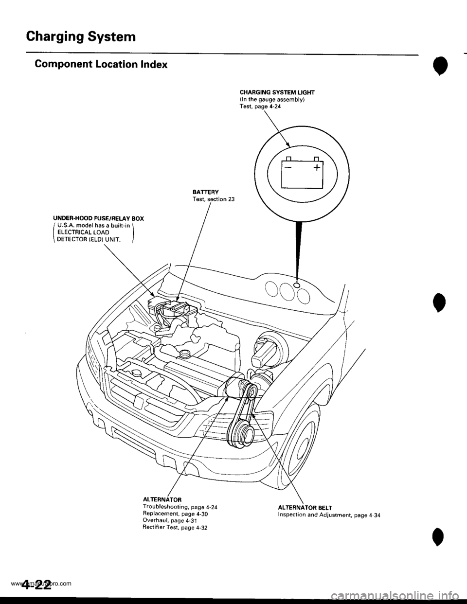
Charging System
Component Location Index
ALTERNATOR
CHARGING SYSTEM LIGHT(ln the gauge assembly)Test, page 4-24
BATTERYTest,
Troubleshooting, page 4-24Replacement, page 4-30Overhaul, page 4-31Rectifjer Test, page 4,32
ALTERNATOR BELTInspection and Adjustment, page 4 34
4-22
www.emanualpro.com
Page 81 of 1395
,T
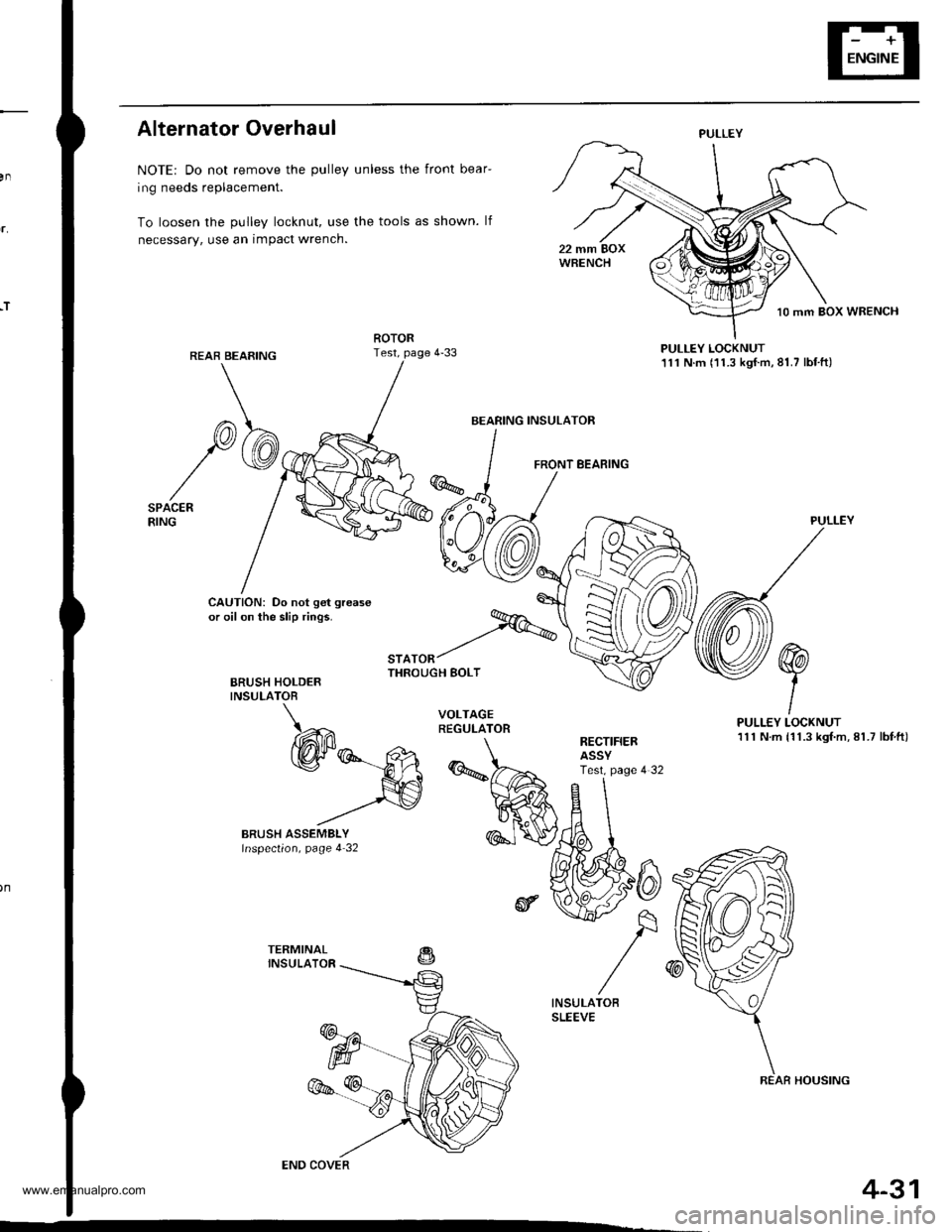
Alternator Overhaul
NOTE: Do not remove the pulley unless the front bear-
ing needs replacement.
To loosen the pulley locknut, use the tools as shown. lf
necessary, use an impact wrench.
PULLEY LOCKNUT111 N.m (11.3 kgf.m,81.7 lbf.ft)
FRONT BEARING
CAUTION: Do not get grease
or oil on the slip rings.
BRUSH HOLDERINSULATOB
"'^.^t%THROUGH BOLT
PULLEY
PULLEY LOCKNUT111 N.m {11.3 kgf.m, 81.7 lbf,ft)RECTIFIERASSYTest. page 4 32
PULLEY
BEARING INSULATOR
COVER
REAR HOUSING
4-31
www.emanualpro.com
Page 149 of 1395
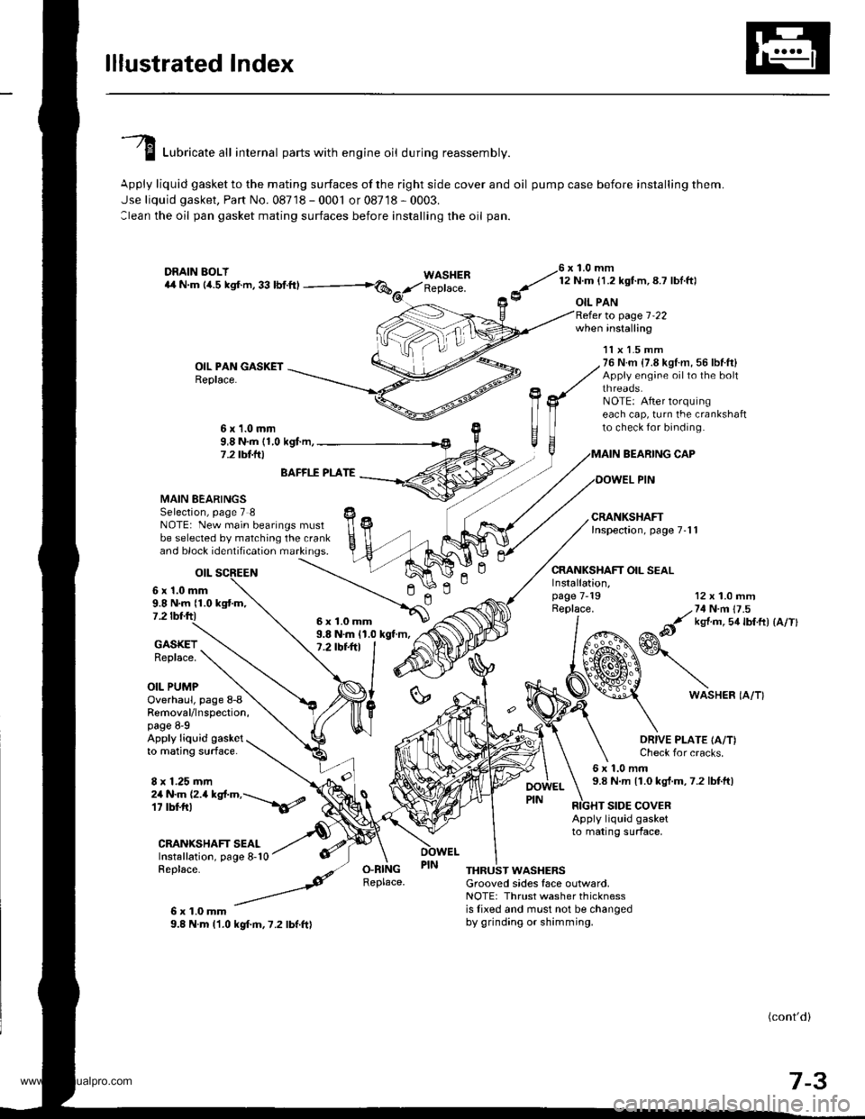
lllustrated lndex
I Luori""t" "tl internal parts with engine oil during reassembly.
Apply liquid gasket to the mating surfaces of the right side cover and oil pump case before installing them.
Jse liquid gasket, Part No. 08718 - 0001 or 08718 - 0003.
:lean the oil pan gasket mating surfaces before installing the oil pan.
WASHERReplace.
76 x 1.0 mm
y' t:n- l.zxstm, 8.7 lbl ftl
9 oIL PAN
OIL PAN GASKETReplace.
to page 1-22when installing
BEARING CAP
OOWEL PIN
CRANKSHAFT OIL SEAL
11x 1.5 mm76 N.m {7.8 kgl.m, 56 lbf.ft}Appiy engine oilto the boltthreaos.NOTE: After lorquingeach cap, turn the crankshaftto check for binding.6x1.0mm9,8 N.m (1,0 kgf.m,7 .2 tbt.lrl
n
MAIN BEARINGSSelection, page 7 8NOTE: New main bearings mustbe selected by matching the crankand block identification markings.
otL
6 x'1.0 mm9.8 N.m {1.0 kgtm,7.2 tbf.ftl
BAFFI.f PLATE
9.8 N.m 11.0 kgt m,7.2 tbt+tl
12 x 1.0 mm
/,71N n 17 .5
&it ks{ m 5a lbtft) {a/Tl
GASKETReplace.
OIL PUMP
Installation,page 7-19Replace.
ln
6WASHER IA/T}Overhaul, page 8-8Removal/lnspection,page 8-9Apply liquid gasketto mating surface.
8 x 1.25 mm
ORIVE PLATE IA/T)Check for cracks.
6x1.0mm9.8 N.m 11.0 kgt.m,7.2 lbtft)2a N.m (2.a kgt.m,---\6/
CRANIGHAFT SEALInstallation, page 8-10Replace-
6x1.0mm9.8 N.m l'1.0 kgf.m,7.2 lbf.ft)
RIGHT SIDE COVERApply liquid gasketto mating surface,
O.RINGReplace.THRUST WASHERSGrooved sides face outlvard,NOTE: Thrust washer thicknessis lixed and must not be changedby grinding or shimming.
(cont'd)
7-3
6x1.0mm
www.emanualpro.com
Page 171 of 1395
Engine Lubrication
Speciaf Tools .......... ...".""'8-2
lllustrated Index ........... .'...8-3
Engine Oil
Inspection ............'..'...'..' 8-4
Replacement ............................'........... 8-4
OilFilter
Rep1acement........................................ 8-5
Oil Pressure Switch
Testing ".....8-7
Oil Pressure
Testing ....'.' 8-7
OilPump
Overhaul..... ...........,......... 8-8
Removal/lnspection/lnstallation ....'.' 8-9
www.emanualpro.com
Page 173 of 1395
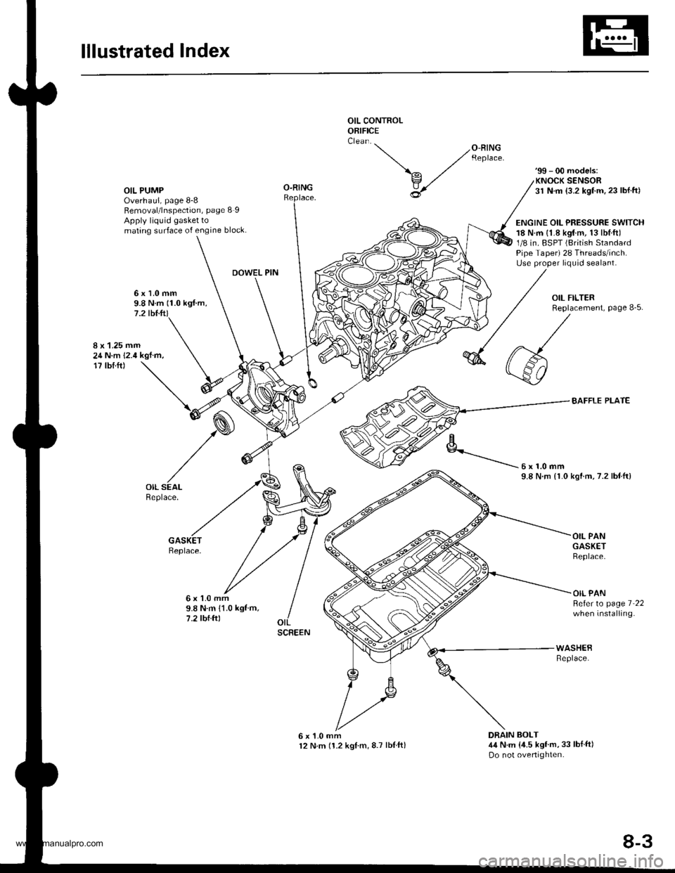
lllustrated Index
OIL CONTROLORIFICE
OIL PUMPOverhaul, page 8-8Removal/lnspection, page 8 IApply liquid gasket tomating surface of engine block.
'99 - 00 models:KNOCK SENSOR31 N.m {3.2 kgf.m.23 lbl.ft)
ENGINE OIL PRESSURE SWITCH18 N.m {1.8 kgtm, 13lbl.ft)1/8 in. BSPT (British StandardPipe Taper) 28 Threads/inch.Use proper liquid sealant.
O-RING
DOWEL PIN
6x1.0mm9.8 N.m (1.0 kgf.m,7.2 tbl.ft)
8 x 1.25 mm24 N.m 12.4 kgf.m,17 tbf.ft)
BAFFLE PLATE
kgtm,7.2 lbtftl
Replace.
6x1.0mm9.8 N.m 11.0 kgf m,7.2 tbf.ftl
OIL PANGASKETReplace.
OIL PANBeferto page 7 22when installing.
6x1.0mm12 N.m 11.2 kglm,8.7 lblftl
WASHEBReplace.
DRAIN BOLT4,1N.m {,1.5 kgf'm,33 lbf ft)Do not overtighten.
'-- /o-RrNG ,/ Reptace.
\^ ./
v,/
U
6x1.0mm9.8 N.rn {1.0
SCREEN
8-3
www.emanualpro.com
Page 174 of 1395
Engine Oil
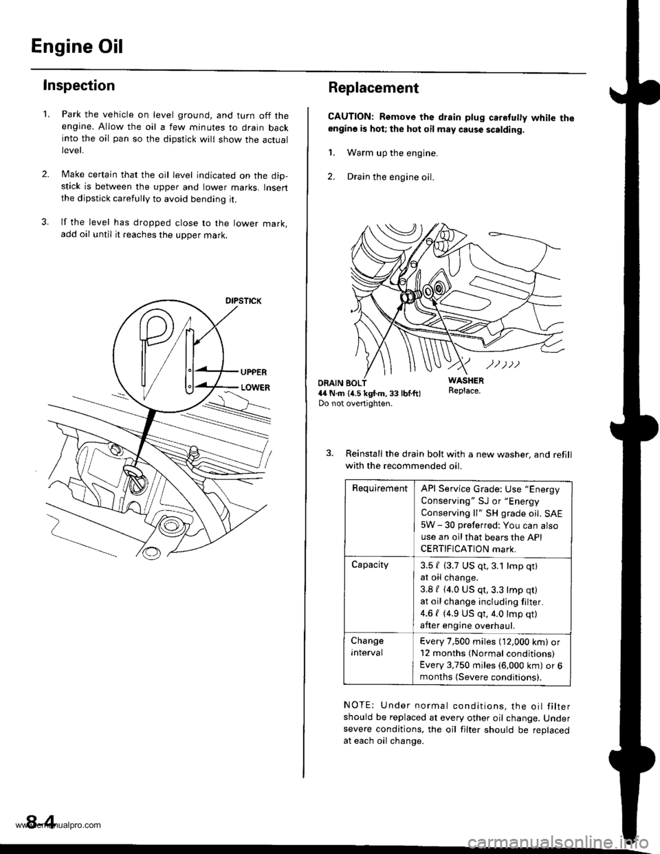
Inspection
2.
1.Park the vehicle on level ground, and turn off theengine. Allow the oil a few minutes to drain backinto the oil pan so the dipstick will show the actuallevet,
Make certain that the oil level indicated on the dip-stick is between the upper and lower marks. Insertthe dipstick carefully to avoid bending it.
lf the level has dropped close to the lower mark,add oil until it reaches the upper mark.
8-4
Replacement
CAUTION: Remove the drain plug caretuly white theengino is hot; the hot oil may cause scalding.
1. Warm up the engine.
2. Drain the engine oil.
WASHERR€place.ORAIN BOL4il N.m {4.5 kgtm,33 lbf.ft)Do not overtighten.
3. Reinstall the drain bolt with a new washer, and refill
with the recommended oil.
RequirementAPI Service Grade: Use "Energy
Conserving " SJ or "Energy
Conserving ll" SH grade oil. SAE
5W - 30 preferred: You can also
use an oil that bears the API
CERTIFICATION mark.
Capacity3.5 { (3.7 US qt,3.1 lmp qt)
at oil change.
3.8 / (4.0 US qt,3.3 lmp qr)
at oil change including filter.
4.6 { (4.9 US qt, 4.0 lmp qt)
after engine overhaul.
Change
Inlerval
Every 7,500 miles (12,000 km) or12 months (Normal conditions)
Every 3,750 miles (6,000 km) or 6months (Severe conditions).
NOTE: Under normal conditions, the oil filtershould be replaced at every other oil change. Undersevere conditions, the oil filter should be replacedat each oil change.
www.emanualpro.com
Page 178 of 1395
Oil Pump
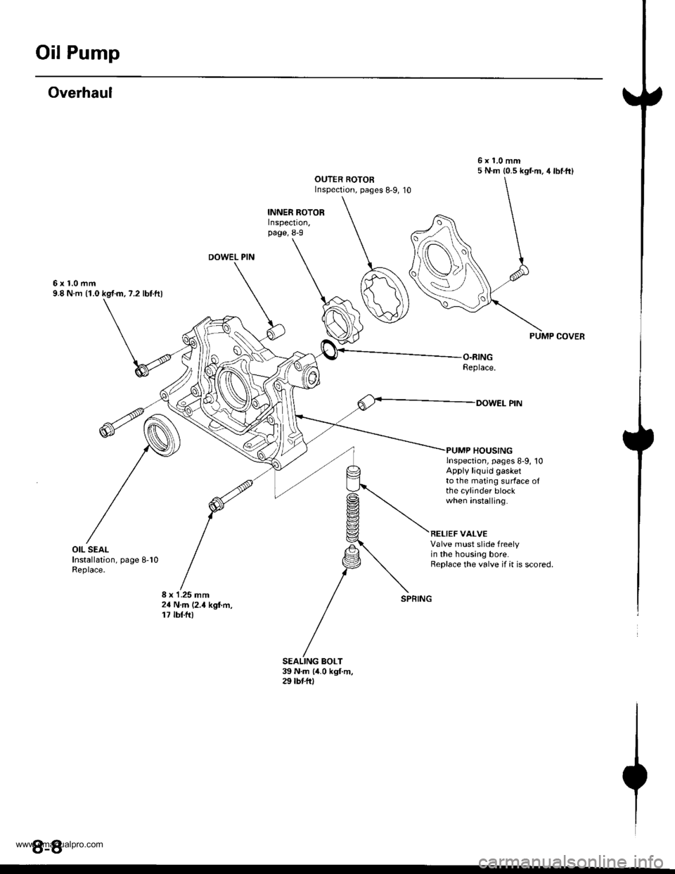
Overhaul
6xl.0mm9.8 N m (1.0 kg,t m, 7.2 lbf ftl
6x1.0mm5 N.m {0.5 kgt m. 4lbtft}OUTER ROTORInspection, pages 8-9, 1O
PUMP COVER
lnspection, pages 8-9, 10Apply liquid gasketto the mating surface ofthe cylinder blockwhen anstalling.
REI-IEF VALVEValve must slide freelyin the housing bore.Replace the valve if it is scored.
8 x 1.25 mm2{ N.m (2.4 kgf m,17 tbf.fi)
DOWEL PIN
8-8
www.emanualpro.com
Page 440 of 1395
Manual Transmission
Diff€rential
lndex ...................... ......... 13-38
Backlash Inspestion ..,....,.,.....................,......, 13-38
Final Driven Gear Replacement .................... 13-39
Tapered Roller BearingReplacement ............. 13-39
Bearing Outer Race Replacement ......,.,........ 13-i10
Tapered Roller Bearing PreloadAdiustment ............... 13-il1
Oil Seal Reolacement .................................... 13-/l:}
Transfer Assembly
lllustrated Index ............. 13-il4
Inspection ..,....,.,......,...... 13-46
Disassembly ................... 13-47
Transfer Drive Gear BearingReplacement ...,..................,....................... 13-ilg
Transfer Driven Gear Shaft BearingReplacement .............................................. 13-ilg
Transfer Shaft Disassembly/Reassembly .............. 13-50
Transler Cover A Bearing Outer RaceRep1acement.........,.,.,..........,....,...,.........,., 13-50
Transter Housing Bearing Outer RaceReD1acement.............................................. 13-51
Reassembly ..-............,... 13-52
Mainshaft Bearing/Oil Seal
Beplacement .................. 13-62
Countershaft Bearing
Replacement .,,.,.,., ..,...... 13-63
Mainshaft Thrust Clearance
Adiustment .................... 13-6,1
Transmission Assembly
Reassembly .,.,.,.,..,.,....,., 13-67
fnstaffation .,.,.............,... 13-72
Gearshift Mechanism
Overhaul ................ .........13-17
www.emanualpro.com
Page 442 of 1395
MaintenanceBack-up Light Switch
Transmission Fluid
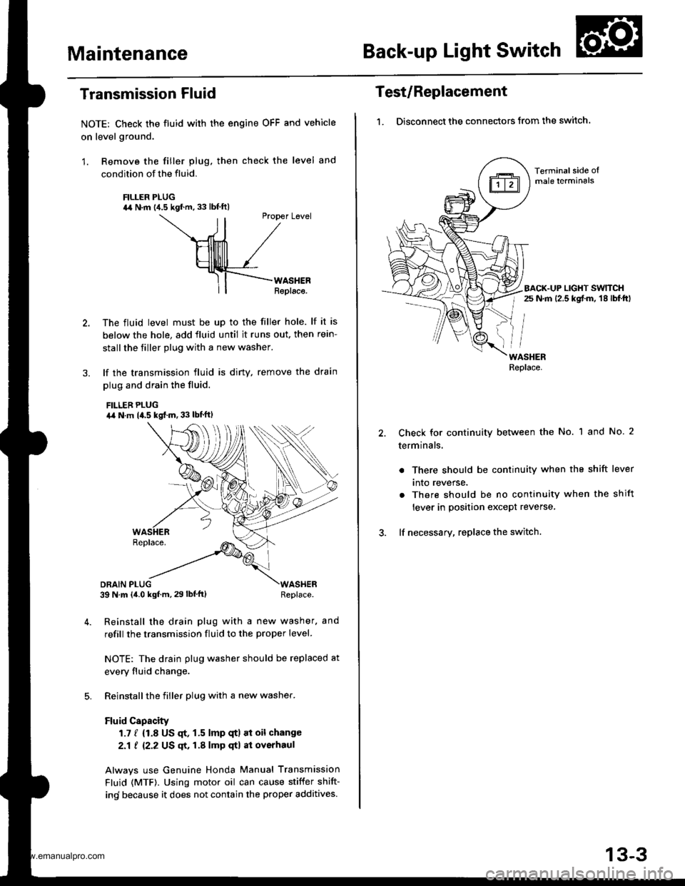
NOTE: Check the fluid with the engine OFF and vehicle
on level ground.
1. Remove the filler plug. then check the level and
condition of the fluid.
FILLER PLUG44 N.m {4.5 kgf.m. 33 lbf ftl
ll
Ptopet Level
\--ril /
HllllllTl /
Hllllrlll /_rf-F{--rno."."
ll| | Replaco.
The fluid level must be up to the filler hole. lf it is
below the hole, add fluid until it runs out. then rein-
stall the tiller plug with a new washer.
lf the transmission fluid is diny, remove the drain
plug and drain the fluid.
FILLEB PLUGa,a N.m 14.5 kgf..n. 33 lbt'ftl
DRAIN PLUG39 N m (4.0 kgf.m, 29 lbf'ft)WASHERReplace.
Reinstall the drain plug with a new washer. and
refill the transmission fluid to the proper level.
NOTE: The drain plug washer should be replaced at
every fluid change.
Reinstall the filler plug with a new washer.
Fluid Capacity
1.7 / {1.8 US qt, 1.5 lmp qtl at oil change
2.1 ! 12.2 US qt, 1.A lmp qtl at overhaul
Alwavs use Genuine Honda Manual Transmission
Fluid (MTF). Using motor oil can cause stiffer shift-
ind because it does not contain the proper additives.
Test/Replacement
1. Disconnect the connectors from the switch.
Terminal side oImale lerminals
BACK.UP LIGHT SWTTCHr 25 N.m 12.5 kgt m, 18 lbf.ftl
WASHERReplace.
Check for continuity between the No. 1 and No. 2
terminals.
. There should be continuity when the shift lever
tnto reverse.
. There should be no continuity when the shift
lever in position except reverse,
lf necessary, replace the switch.
13-3
www.emanualpro.com
Page 516 of 1395
Gearshift Mechanism
Overhaul
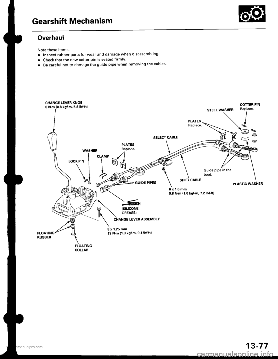
Note these itemsl
. InsDect rubber parts for wear and damage when disassembling'
. Check that the new cotter pin is seated firmly.
. Be carelul not to damage the guide pipe when removing the cables'
CHANGE LEVER KNOS8 N.m (0.8 kgl.m, 5.8 lbf.ft)
SELECT CABLE
PLATESReplace.WASHEB
I curur(PlN I I
\II
\"1 a,?-@ -.4'
-(
I
\
6x9.8
Guide pipe in theDOOI,
COTTEF PIN
PLASTIC WASHERGUIDE PIPESSHIFT CABLE
'l.0 mmN.m {1.0 kgf.m, 7.2 lbf.ftl
(stLlcoNE
GREASEI
LEVER ASSEMBLY
8 x 1.25 mm13 N.m 11.3 kgt'm,9.4lbf ft)
FLOATINGCOLLAR
13-77
www.emanualpro.com