Piston rings HONDA CR-V 1999 RD1-RD3 / 1.G User Guide
[x] Cancel search | Manufacturer: HONDA, Model Year: 1999, Model line: CR-V, Model: HONDA CR-V 1999 RD1-RD3 / 1.GPages: 1395, PDF Size: 35.62 MB
Page 716 of 1395
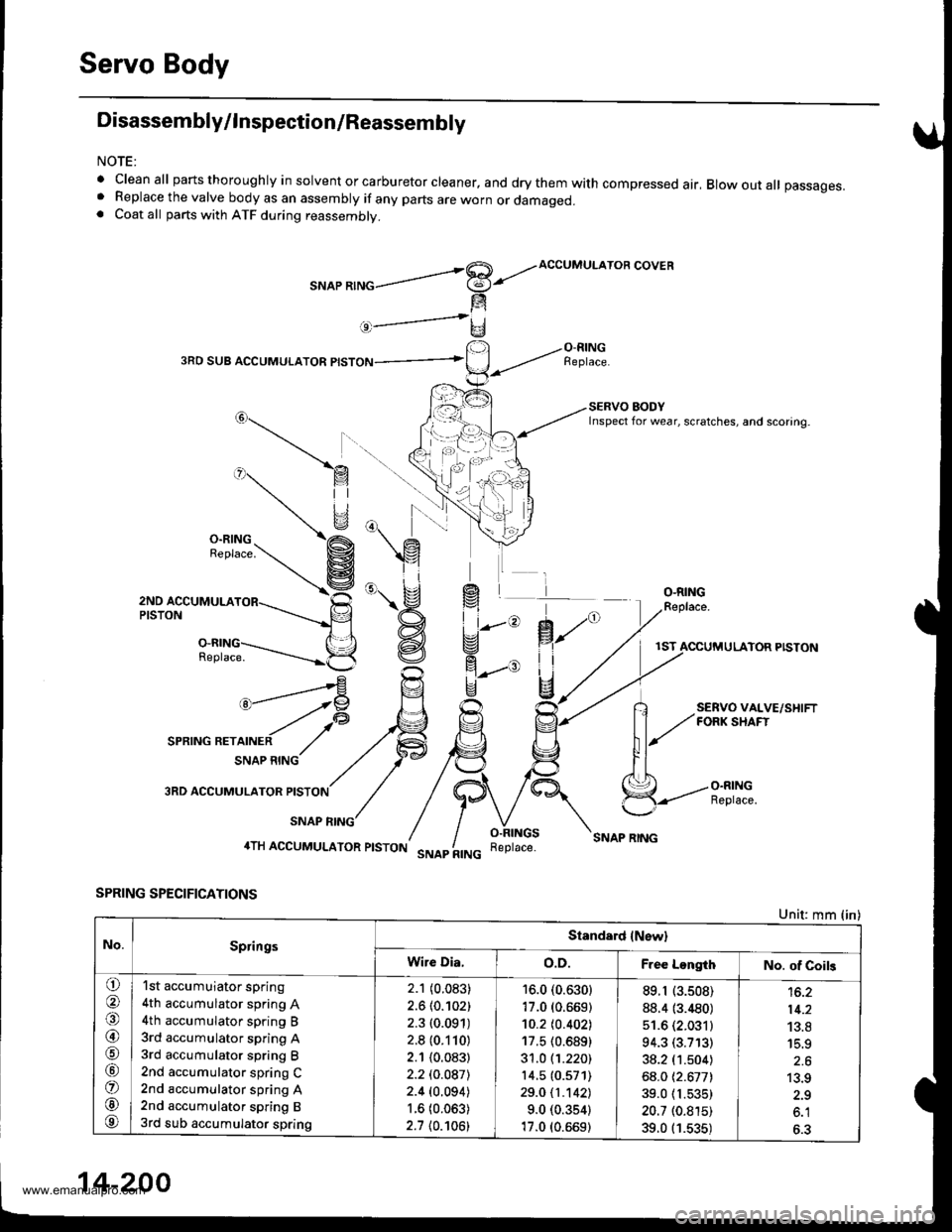
Servo Body
Disassembly/lnspection/Reassembly
NOTE:
' cleanall parts thoro ugh ly in solvent or ca rbu retor clea ner, a nd dry them with compressed air, Blow out all passages.. Replace the valve body as an assembly if any parts are worn or damaged.. Coat all parts with ATF during reassembly.
ACCUMULATOR COVER
3RO SUB ACCUMULATOR
O-RINGFeplace.
SERVOFORK S
fi,
il
g
1ST ACCUMULATOR PISTON
Replace.
RVO VAL\IRK SHAFT
O.RING
VE/SHIFT
3RD ACCUMULATOR
SPRING SPECIFICATIONS
\_)
SNAP RING
SNAP RING
Unit: mm {in)
@"- -tP
-.t l@SPR|NG RETATNER ,/
No.SpringsStandard lNewl
Wire Dia,o.D.Free LongthNo. of Coil3
o
@J6
@.A
\o,
o
@
@
1st accumuiator spring
4th accumulator spring A
4th accumulator spring B
3rd accumulator spring A
3rd accumulator spring B
2nd accumulator spring C2nd accumulator spring A2nd accumulator spring B
3rd sub accumulator spring
2.1 (0.083)
2.6 {0.102)
2.3 (0.091)
2.8 (0.110)
2.1 (0.083)
2.2 (0.087l-
2.4 (0.094)
r.6 (0.063)
2.7 {0.106)
16.0 (0.6301
17.0 (0.669)'t0.2 t0.402]�
17.5 (0.689)
31.0 (1.220)
14.5 {0.571)
29.0 11.1421
9.0 (0.354)
17.0 (0.669)
89.r (3.508)
88.4 (3.480)
51.6 (2.031)
94.3 (3.713)
38.2 (1.504)
68.0 {2.677)
39.0 fi.535)
20.7 (0.815)
39.0 (1.535)
14.2
13.8
15.9
2.6
13.9
2.9
o.l
6.3
14-200
www.emanualpro.com
Page 731 of 1395
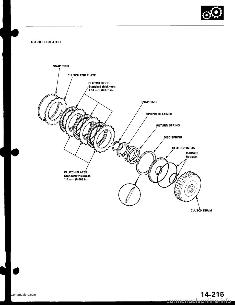
lST-HOLD CLUTCH
thickness:
RETURN SPRING
c
/
LUTCH PISTON
O.RINGS
14-215
www.emanualpro.com
Page 734 of 1395
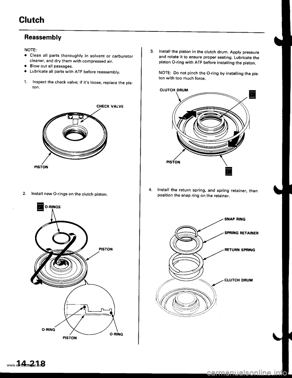
Glutch
Reassembly
NOTE:
. Clean all parts thoroughly in solvent or carburetorcleaner, and dry them with compressed air.. Blow out all passages.
o Lubricate all parts with ATF before reassembly.
1. Inspect the check valve; if it's loose, replace the pis_ton.
CHECK VALVE
2. Install new O-rings on the clutch piston.
PtsTot{
14-218
3. Install th€ piston in the clutch drum. Apply pressure
and rotate it to ensure proper seating, Lubricate thepiston O-ring with ATF betore insta ing the piston.
NOTE: Oo not pinch the O-ring by installing the pis_ton with too much force.
CLUTCH DRUM
Install the return spring, and spring retainer, thenposition the snap ring on the retainer.
4.
SI{AP RING
SPAI'{G RETAIIIER
REIURN SPRING
CLUTCH DRUM
www.emanualpro.com
Page 798 of 1395
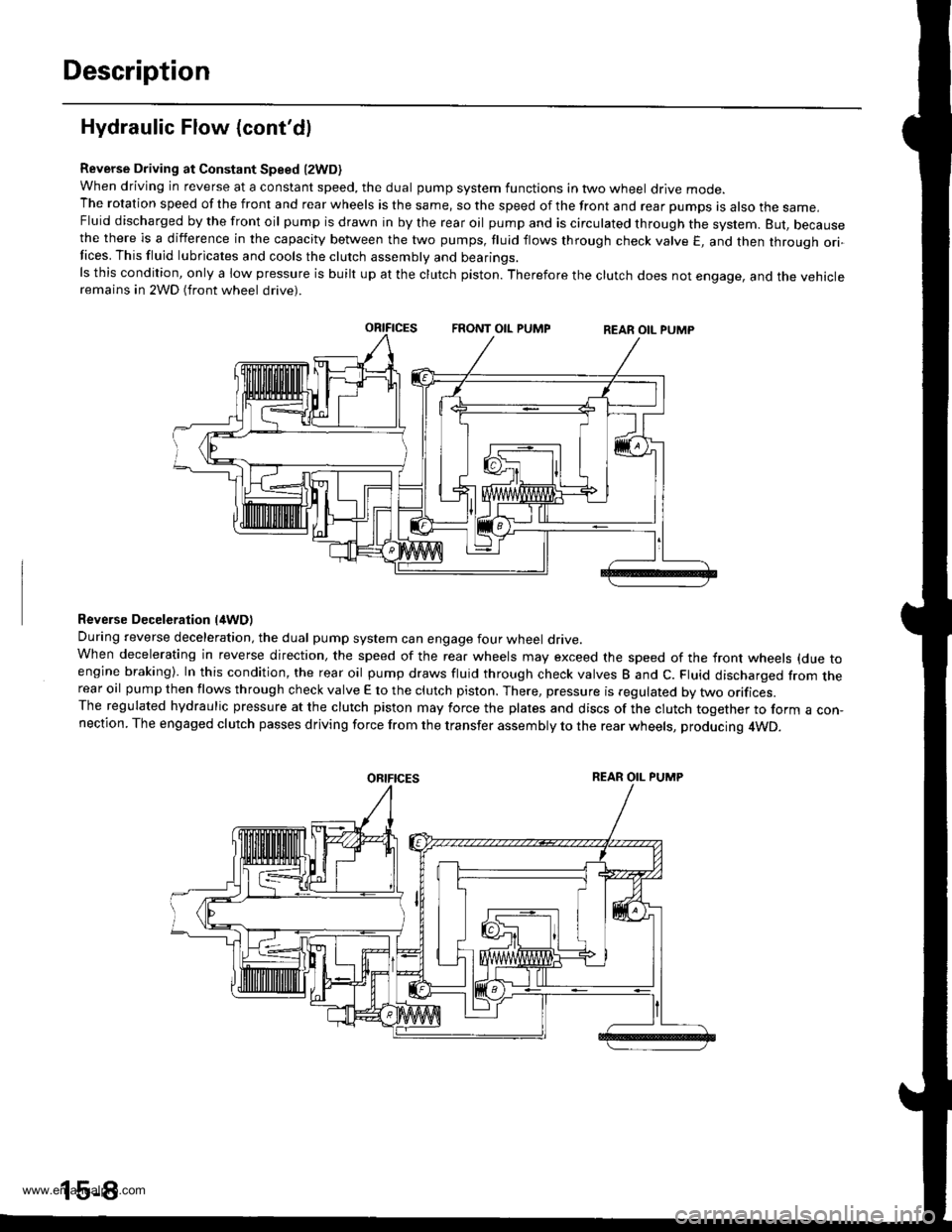
Description
Hydraulic Flow (cont'dl
Reverse Driving at Constant Speed l2WD)when driving in reverse at a constant speed, the dual pump system functions in two wheel drive mode.The rotation speed of the front and rear wheels is the same, so the speed of the front and rear pumps is also the same,Fluid discharged by the front oil pump is drawn in by the rear oil pump and is circulated through the system. But, becausethe there is a difference in the capacity between the two pumps, fluid flows through check valve E, and then through ori-Iices. This fluid lubricates and cools the clutch assembly and bearings.ls this condition, only a low pressure is built up at the clutch piston. Therefore the clutch does not engage, and the vehicleremains in 2WD (front wheel drive).
Reverse Deceleration l/tWDl
During reverse deceleration, the dual pump system can engage four wheel drive.When decelerating in reverse direction, the speed of the rear wheels may exceed the speed of the front wheels (due toengine braking). In this condition, the rear oil pump draws fluid through check valves B and C. Fluid discharged from therear oil pump then flows through check valve E to the clutch piston. There, pressure is regulated by two orifices.The regulated hydraulic pressure at the clutch piston may force the plates and discs of the clutch together to form a con,nection. The engaged clutch passes driving force from the transfer assembly to the rear wheels, producing 4WD.
oRtFtcEsREAR OIL PUMP
www.emanualpro.com
Page 885 of 1395
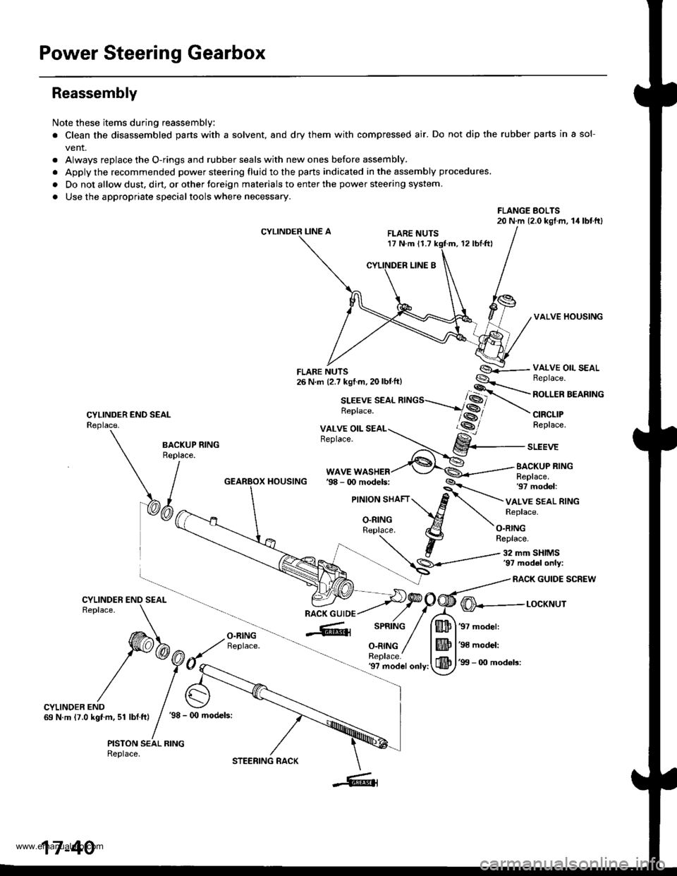
Power Steering Gearbox
Reassembly
Note these items during reassembly
. Clean the disassembled parts with a solvent, and dry them with compressed air. Do not dip the rubber parts in a sol-
vent.
. Always replace the O-rings and rubber seals with new ones before assembly.
. Apply the recommended power steering fluid to the parts indicated in the assembly procedures.
. Do not allow dust. dirt, or other toreign materials to enter the power steering system.
. Use the appropriate specialtools where necessary.
FLANGE BOLTS20 N.m (2.0 kgl.m, 14lbtftl
CYLINDER LINE AFLARE NUTS17 N.m 11.712 rbl.ftl
VALVE HOUSING
CYLINDER END SEALReplace.
VALVE OIL SEALBeplace.
ROLLER BEARING
CIRCLIPReplace.
BA.KUP RING
\/^"
WAVE WASHERBACKUP RINGReplace.97 model:HOUSING
VALVE SEAL RINGReplace.
O.RINGReplace.
32 mm SHIMS'97 mod6l only:
RACK GUIDE SCREW
O-RINGReplace.
@---r-ocxr'rur
'97 model:
'98 model:
'99 - 0O mod6ls:'9? model only:
CYLINDER END69 N.m (7.0 kgf.m, 51 lbf.ft)'98 - (x) models:
PISTON SEAL RINGReplace.
17-40
STEERING RACK
www.emanualpro.com
Page 889 of 1395
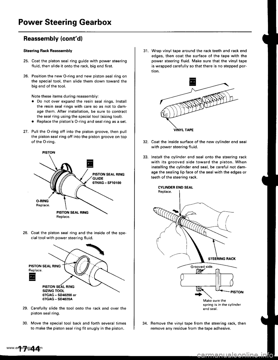
Power Steering Gearbox
Reassembly (cont'dl
Stecring Rack R8assembly
25. Coat the piston seal ring guide with power steering
fluid, then slide it onto the rack, big end first.
26. Position the new O-ring and new piston seal ring on
the sDecial tool, then slide them down toward the
big end of the tool.
Note these items during reassembly:
a Do not over expand the resin seal rings. Install
the resin seal rings with care so as not to dam-
age them. After installation, be sure to contract
the seal ring using the special tool (sizing tool).
a Replace the piston's O-ring and seal ring as a set.
27. Pull rhe O-ring off into the piston groove, then pull
the piston seal ring off into the piston groove on top
of the O-ring.
Coat the piston seal ring and the inside of the spe-
cial tool with power steering fluid.
07GAG - SO4O200 orOTGAG - SD'()2OA
Carefully slide the tool onto the rack and over thepiston seal ring.
Move the special tool back and fonh several times
to make the piston seal ring fit snugly in the piston.
24.
PISTONReplace
E
30.
PISTON
17-44
31. Wrap vinyl tape around the rack teeth and rack end
edges, then coat the surface of the tape with the
power steering fluid. Make sure that the vinyl tape
is wrapped carefully so that there is no stepped por-
tion.
Coat the inside surface of the new cvlinder end
with power steering fluid.
Install the cylinder end seal onto the steering rack
with its grooved side toward the piston. When
installing the cylinder end seal, be careful not dam-
age the sealing lip face of the seal with the edges or
teeth of the steering rack.
CYLINDER END SEAL
Make sure thespring is in lhe cylindereno seal
Remove the vinyl tape from the steering rack, then
remove any residue from the tape adhesive.
www.emanualpro.com