Valve HONDA CR-V 1999 RD1-RD3 / 1.G Workshop Manual
[x] Cancel search | Manufacturer: HONDA, Model Year: 1999, Model line: CR-V, Model: HONDA CR-V 1999 RD1-RD3 / 1.GPages: 1395, PDF Size: 35.62 MB
Page 767 of 1395
1.Install the suction pipe collar and the ATF magnet
{2WD) in the torque converter housing, if necessary.
lnstall the main seDarator Dlate and the two dowel
pins on the torque converter housing,
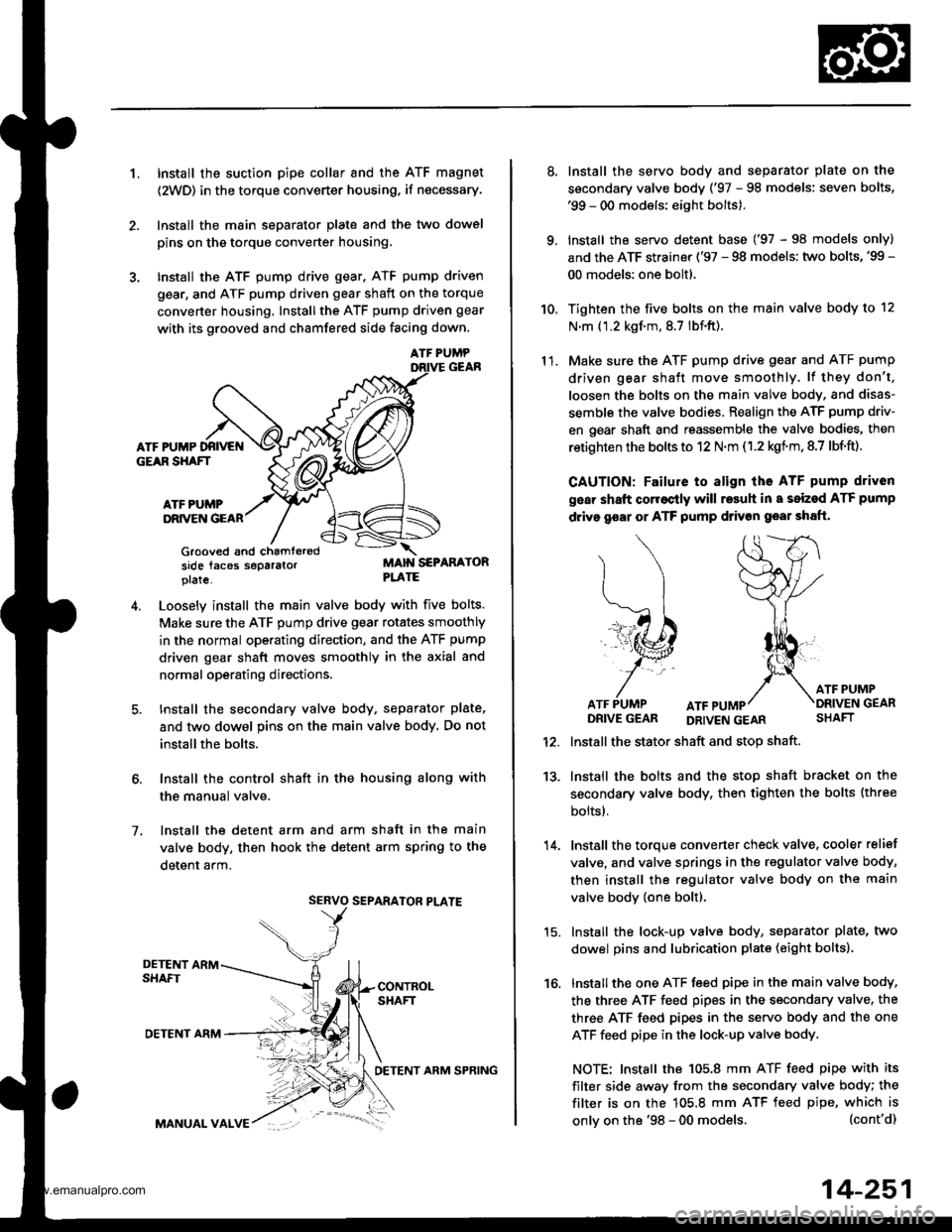
Install the ATF pump drive gear. ATF pump driven
gear, and ATF pump driven gear shaft on the torque
converter housing. Installthe ATF pump driven gear
with its grooved and chamfered side facing down.
ATF PUMPGEAR
ATF PUMP D{IVEf{GEAR SHAFT
ATF PUi'PORIVEN GEAR
Grooved and chamteredside faces separatorplate.
MAIN S€PAR/ATORPLATE
5.
o.
Loosely install the main valve body with five bolts.
Make sure the ATF pump drive gear rotates smoothly
in the normal operating direction, and the ATF pump
driven gear shaft moves smoothly in the axial and
normal operating directions.
Install the secondary valve body, separator plate,
and two dowel pins on the main valve body. Do not
installthe bolts.
Install the control shaft in the housing along with
the manual valve.
lnstall the detent arm and arm shaft in the main
valve body, then hook the detent arm spring to the
detent arm.
SEBVO SEPARATOR PLATE
7.
DETENT ARMSHAFT
OETENT ARM
CONTROLSHAFT
MANUAL VAIVE
OETENT ARM SPRING
onlv on the '98 - 00 models,
14-251
1l.
9.
8.
10.
Install the servo body and separator plate on the
secondary valve body ('97 - 98 models: seven bolts,'99 - 00 models: eight bolts).
lnstall the servo detent base ('97 - 98 models only)
and the ATF strainer ('97 - 98 models: two bolts,'99 -
00 models: one boltl.
Tighten the five bolts on the main valve body to 12
N'm (1.2 kgf.m, 8.7 lbf.ft).
Make sure the ATF pump drive gear and ATF pump
driven gear shaft move smoothly. lf they don't,
loosen the bolts on the main valve body, and disas-
semble the valve bodies. Realign the ATF pump driv-
en gear shaft and reassemble the valve bodies, then
retighten the bolts to 12 N.m (1.2 kgim, 8.7 lbf.ft).
CAUTION: Failure to align the ATF pump driven
gear shaft corroctly will rosult in a seizsd ATF pump
drive gear or ATF pump drivon gear shaft.
ATF PUMP ATFGEARDRIVE GEAR DBIVEN GEARSHAFT
Install the stator shaft and stop shaft
Install the bolts and the stop shaft bracket on the
secondary valve body, then tighten the bolts (three
bolts).
Install the torque converter check valve, cooler relief
valve, and valve springs in the regulator valve body,
then install the regulator valve body on the main
valve body {one boltl.
Install the lock-up valve body, separator plate, two
dowel pins and lubrication plate (eight bolts).
Installthe one ATF feed pipe in the main valve body,
the three ATF feed pipes in the secondary valve, the
three ATF feed pipes in the servo body and the one
ATF feed pipe in the lock-up valve body.
NOTE: lnstall the 105.8 mm ATF feed pipe with its
filter side away from the secondary valve body; the
filter is on the 105.8 mm ATF feed pipe, which is(cont'd)
13.
14.
15.
16.
www.emanualpro.com
Page 778 of 1395
Transmission
Installation (cont'dl
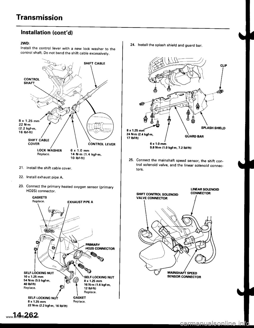
2WD:
Install the control lever with a new lock washer to thecontrol shaft. Do not bend the shift cable excessivelv.
8 r 1.25 mm22 N.m|'2.2 kgt.m,16 rbf.ft)
SI{IFT CAELECOVER
LOCK WASHER 6 x 1.0 mmReplace. 14 N.m 11.4 kgt.m,10 tbr.frl
lnstallthe shift cable cover.
Install exhaust pipe A.
Connect the primary heated orygen sensor (primary
HO2S) connector.
GASKETSReplace.
22.
23.
10 x 1.25 m.n5r N.m {5.5 kgf.m,40 tbtftlReplace.
SELF.LOCKING
SELF-LOCKING NUT8 ! 1.25 mm16 N.m {1.6 kgf.m,12 lbf.fttReplace.
8 x 1.25 mm22 N.m {2,2 kgt.m, l5 lbt.ftl
SHIFT CABLE
14-262
24. Installthe splash shield and guard bar,
8 x 1.2524 N.m {2.a kgl.m,17 tbt.ftl
SPLASH SHIELD
GUARO BAR
25.
6r1.0|r|m9.8 N.m l1.0lgf.m, 7.2 tbtftl
Connect the mainshaft speed sensor, the shift con-trol solenoid valve, and the linear solenoid connec_tors,
SHIFT CONTROL SOLENOIDVALVE CONNECTOR
www.emanualpro.com
Page 779 of 1395

26. Connect the vehicle speed sensor (VSS). the coun-
tershaft speed sensor. and the A,/T gear position
switch connectors,
VEHICLE SPEEO
SPEED SENSOACO'{NECTOR
Connect the lock-up control solenoid valve connec-
tor, then install the harness clamp on the clamp
bracket.
HARNESS CI-AMP
27.
RADIATOR HOSECLAMP
TRANSMISSIONGROUND CAB1ITERMINAL
LOCK-UP OONTROLSOLENOID VALVECONNECTOR
6x1.0mm12 N'm (1.2 kgi.m,8.? tbtftl
28.
29.
Instail the transmission ground cable terminal on
the transmission hanger, and install the radiator
hose clamp on the transmission hanger,
Connect the starter cables to the starter, and install
the harness clamD on the clamD bracket. Make sure
the crimped side of the starter cable ring terminal is
facing out.
STARTEBCABLE
STARTER CAAtf,
Install the air cleaner housing assembly and the
intake air duct.
Refill the transmission with ATF (see page 14-161).
Connect the battery positive terminal and negative
terminal.
Set the parking brake, Start the engine, and shift the
transmission through all gears three times.
Check the shift cable adjustment (see page 14-271]-.
Check the tront wheel alignment and adjust it if
needed (see section 18).
Let the engine reach normal operating temperature
(the radiator fan comes on) with the transmission in
E or N position, then turn it off and check the ATF
level {see page 14-160).
Perform a road test (see page 14-157 and 14-158).
30.
31.
34.
CLAMP BRACKET
37.
14-263
www.emanualpro.com
Page 780 of 1395
Transmission
Cooler Flushing
@@ To prevent in;ury to face and eyos, atwayswear safety glasses ot a face shield when using thetlansmission flusher.
This procedure should be performed before reinstallingthe transmission.
2.
LCheck equipment for wear and cracks before using.Replace any worn or cracked components.
Using the measuring cup. fill the tank with 21 ounces{approximately 213 lull) ol biodegradable flushingfluid (J35944 - 20). Do not substitute with any otherfluid. Follow the handling procedure on the fluidcontaaner.
Secure the flusher filler cap, and pressurize theflusher with compressed air to 550 - 829 kpa (5.6 _
8.45 kgf/cm,, 80 - 120psi). The air line should beequipped with a water trap to ensure a dry air sys-tem.
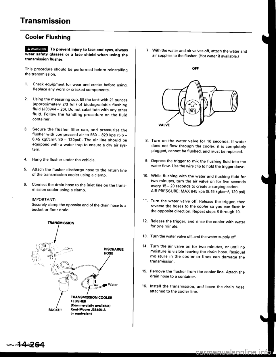
Hang the flusher under the vehicle.
Attach the flusher discharge hose to the return lineof the transmission cooler using a clamp.
Connect the drain hose to the inlet line on the trans-mission cooler using a clamp.
IMPORTANT:
Securely clamp the opposite end ofthe drain hose to abucket or floor drain.
DISCHARGEHOSE
tAirlp Water
TnAI{SrfiSStoN coot"€RFLUSHER{Comm.rcidly.v.il.bt.lK.r -Moor. J38,t{15.Aor aquival.nt
5.
14-264
7. With the water and air valves off, attach the water andair supplies to the flusher. (Hot water if available.)
10.
8.
1'�I.
Turn on the water valve for 1O seconds. lf waterdoes not flow through the cooler, it is completelyplugged, cannot be flushed, and must be replaced.
Depress the trigger to mix the flushing fluid into thewater flow. Use the wire clip to hold the trigger down.
While flushing with the water and flushing fluid fortwo minutes, turn the air valve on for five secondsevery 15 - 20 seconds to create a surging action.AIR PRESSURE: MAX 845 kpa (8.45 kgf/cmr, t20 psi)
Turn the water valve off. Release the trigger, thenreverse the hoses to the cooler so you can flush inthe opposite direction. Repeat steps 8 through 10.
Release the trigger, and rinse the cooler with wate.for one minute.
Turn the water valve off, and the water supply off.
Turn the air valve on for two minutes, or until nomoisture is visible leaving the drain hose. Residualmoisture in the cooler or lines can damage thetransmission.
Remove the flusher from the cooler line. Attach thedrain hose to a container.
Install the transmission, and leave the drain hoseattached to the cooler line.
12.
13.
14.
to.
www.emanualpro.com
Page 795 of 1395
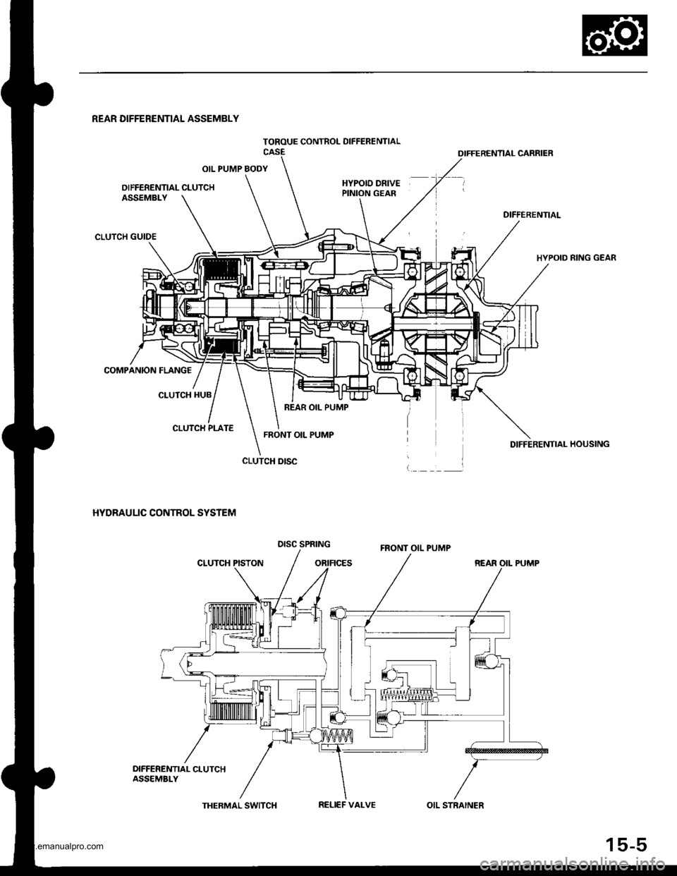
TOROUE CONTROL OIFFERENTIAL
REAR DIFFERENTIAL ASSEMBLY
OIL PUMP BODY
OIFFERENTIAL CLUTCHHYPOID DRIVEPINION GEAR
OIFFERENTIAL CARRIER
DIFFERENTIAL
HYPOID RING GEAR
DIFFERENTIAI- HOUSING
REAR OII- PUMP
ASSEMBLY
CLUTCH GUIDE
COMPANION FLANG€
CLUTCH HUB
CLUTCH PLATE
HYDRAULIC CONTROL SYSTEM
CLUTCH PISTON
CLUTCH DISC
REAR OIL PUMP
FRONT OIL PUMP
DISC SPRINGFRONT OIL PUMP
DIFFEREMT|AL CLUTCHASSEMBI-Y
THERMAL SWITCHRELIEF VALVEOIL STRAINER
15-5
www.emanualpro.com
Page 796 of 1395
Description
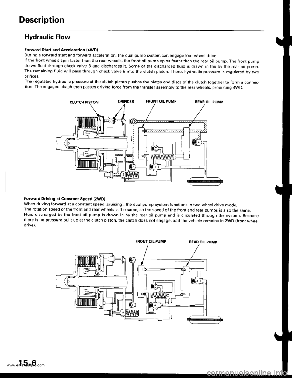
Hydraulic Flow
Forward Start and Acceleration l4WD)During a forward start and forward acceleration, the dual pump system can engage four wheel drive.lf the front wheels spin faster than the rear wheels, the front oil pump spins faster than the rear oil pump. The front pump
draws fluid through check valve B and discharges it. Some of the discharged fluid is drawn in the by the rear oil pump.The remaining fluid will pass through check valve E into the clutch piston. There, hydraulic pressure is regulated by twoorifices.
The regulated hydraulic pressure at the clutch piston pushes the plates and discs of the clutch together to form a connec-tion. The engaged clutch then passes driving force from the transfer assembly to the rear wheels, producing 4WD.
oRrFtcEsFRONT OIL PUMPREAR OIL PUMP
Forward Driving at Constant Speed lzWD)When driving forward at a constant speed (cruising), the dual pump system functions in two wheel drive mode.The rotation speed of the front and rear wheels is the same, so the speed of the front and rear pumps is also the same.Fluid discharged by the front oil pump is drawn in by the rear oil pump and is circulated through the system. Becausethere is no pressure built up at the clutch piston, the clutch does not engage, and the vehicle remains in 2WD (front wheeldrive).
FRONT OIL PUMP
15-6
www.emanualpro.com
Page 797 of 1395
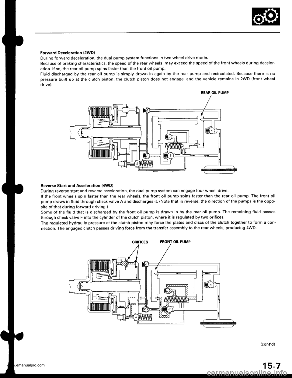
Forward Deceleration l2WDl
During forward deceleration, the dual pump system functions in two wheel drive mode.
Because of braking characteristics, the speed of the rear wheels may exceed the speed ol the front wheels during deceler-
ation. lf so, the rear oil pump spins faster than the front oil pump.
Fluid discharged by the rear oil pump is simply drawn in again by the rear pump and recirculated. Because there is no
pressure built up at the clutch piston. the clutch piston does not engage, and the vehicle remains in 2WD (front wheel
drive).
Reverse Start and Acceleration (4WD)
During reverse start and reverse acceleration, the dual pump system can engage four wheel drive.
lf the front wheels spin faster than the rear wheels, the front oil pump spins faster than the rear oil pump. The front oil
pump draws in fluid through check valve A and discharges it. {Note that in reverse, the direction of the pumps is the oppo-
site of that during forward driving.)
Some of the fluid that is discharged by the front oil pump is drawn in by the rear oil pump. The remaining fluid passes
through check valve F into the cylinder of the clutch piston, where it is regulated by two orifices.
The regulated hydraulic pressure at the clutch piston may force the plates and discs of the clutch together to form a con-
nectlon. The engaged clutch passes driving force from the transfer assembly to the rear wheels, producing 4WD.
oRtFtcEsFRONT OIL PUMP
{cont'd)
15-7
REAR OIL PUMP
www.emanualpro.com
Page 798 of 1395
Description
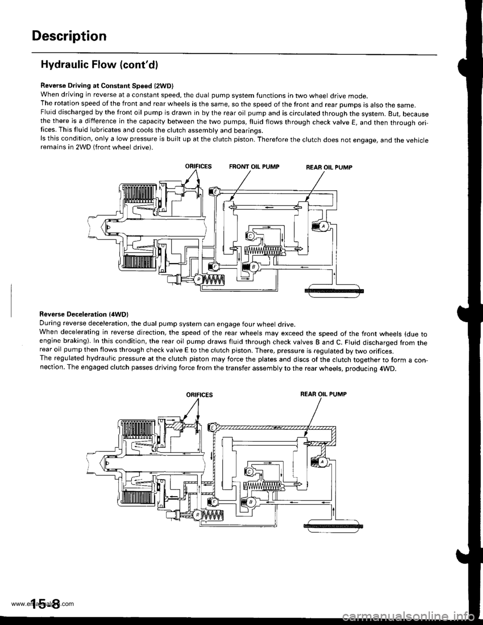
Hydraulic Flow (cont'dl
Reverse Driving at Constant Speed l2WD)when driving in reverse at a constant speed, the dual pump system functions in two wheel drive mode.The rotation speed of the front and rear wheels is the same, so the speed of the front and rear pumps is also the same,Fluid discharged by the front oil pump is drawn in by the rear oil pump and is circulated through the system. But, becausethe there is a difference in the capacity between the two pumps, fluid flows through check valve E, and then through ori-Iices. This fluid lubricates and cools the clutch assembly and bearings.ls this condition, only a low pressure is built up at the clutch piston. Therefore the clutch does not engage, and the vehicleremains in 2WD (front wheel drive).
Reverse Deceleration l/tWDl
During reverse deceleration, the dual pump system can engage four wheel drive.When decelerating in reverse direction, the speed of the rear wheels may exceed the speed of the front wheels (due toengine braking). In this condition, the rear oil pump draws fluid through check valves B and C. Fluid discharged from therear oil pump then flows through check valve E to the clutch piston. There, pressure is regulated by two orifices.The regulated hydraulic pressure at the clutch piston may force the plates and discs of the clutch together to form a con,nection. The engaged clutch passes driving force from the transfer assembly to the rear wheels, producing 4WD.
oRtFtcEsREAR OIL PUMP
www.emanualpro.com
Page 799 of 1395
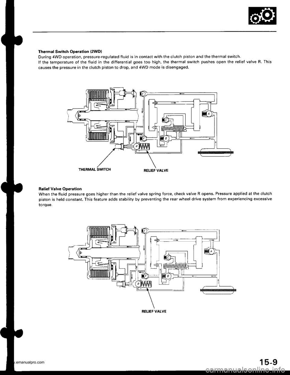
Thermal Switch Operation l2WD)
During 4WD operation, pressure-regulated fluid is in contact with the clutch piston and the thermal switch.
lf the temperature of the fluid in the differential goes too high, the thermal switch pushes open the relief valve R. This
causes the pressure in the clutch piston to drop, and 4WD mode is disengaged.
THERMAL SWITCHRELIEF VALVE
Reliet Valve Operation
When the fluid pressure goes higher than the relief valve spring force, check valve R opens. Pressure applied at the clutch
piston is held constant. This feature adds stability by preventing the rear wheel drive system from experiencing excessive
to rque.
RELIEF VALVE
15-9
www.emanualpro.com
Page 847 of 1395
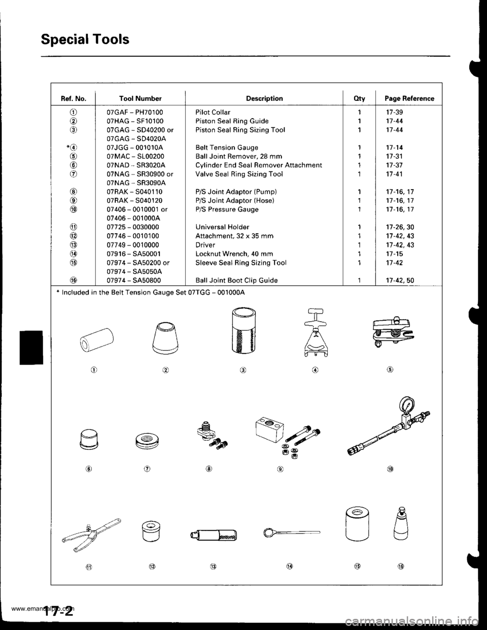
Ret. No, I Tool NumbelDescriptionfty Page Reference
o
o
-@
€r
o
@rol
@
o
@
@(}
@
@
07GAF - PH70100
07HAG - SF10100
07GAG - SD40200 or
OTGAG - SD4O2OA
07JGG - 001010A
07MAC - S100200
OTNAD _ SR3O2OA
07NAG SR30900 or
07NAG , SR3OgOA
07RAK - 50401 10
07RAK - 5040120
07406 - 0010001 or
07406 - 0010004
07725 - 0030000
07746 - 0010100
07749 - 0010000
07916 - SA50001
07974 - SA50200 or
07974 - SA5050A
07974 - SA50800
Pilot Collar
Piston Seal Ring Guide
Piston Seal Ring Sizing Tool
Belt Tension Gauge
Ball Joint Remover,23 mm
Cylinder End Seal Remover Attachment
Valve Seal Ring Sizing Tool
P/S Joint Adaptor (Pump)
P/S Joint Adaptor (Hose)
P/S Pressure Gauge
Universal Holder
Attachment, 32 x 35 mm
Driver
Locknut Wrench, 40 mm
Sleeve Seal Ring Sizing Tool
Ball Joint Boot Clip Guide
'l
1
1
1
1
1
1
1
1
1
1
1
1,l
1
1
11-39
17-44
11-44
17 -14't]-31
17 -37't7 -4'l
17-'t6, 17
17-16, 17
11-16, 17
17-26,30't]-42, 43't1-42, 43
11-15't]-42
11-42, 50
* Included in the Belt Tension Gauge Set 07TGG - 001000,4
o@
\J
,/:\
I
o
,€l-
=tt
@@
aA)
l:I/\L----.--.--------_
@o(D(9@@
17-2
www.emanualpro.com