Valve HONDA CR-V 1999 RD1-RD3 / 1.G Workshop Manual
[x] Cancel search | Manufacturer: HONDA, Model Year: 1999, Model line: CR-V, Model: HONDA CR-V 1999 RD1-RD3 / 1.GPages: 1395, PDF Size: 35.62 MB
Page 957 of 1395
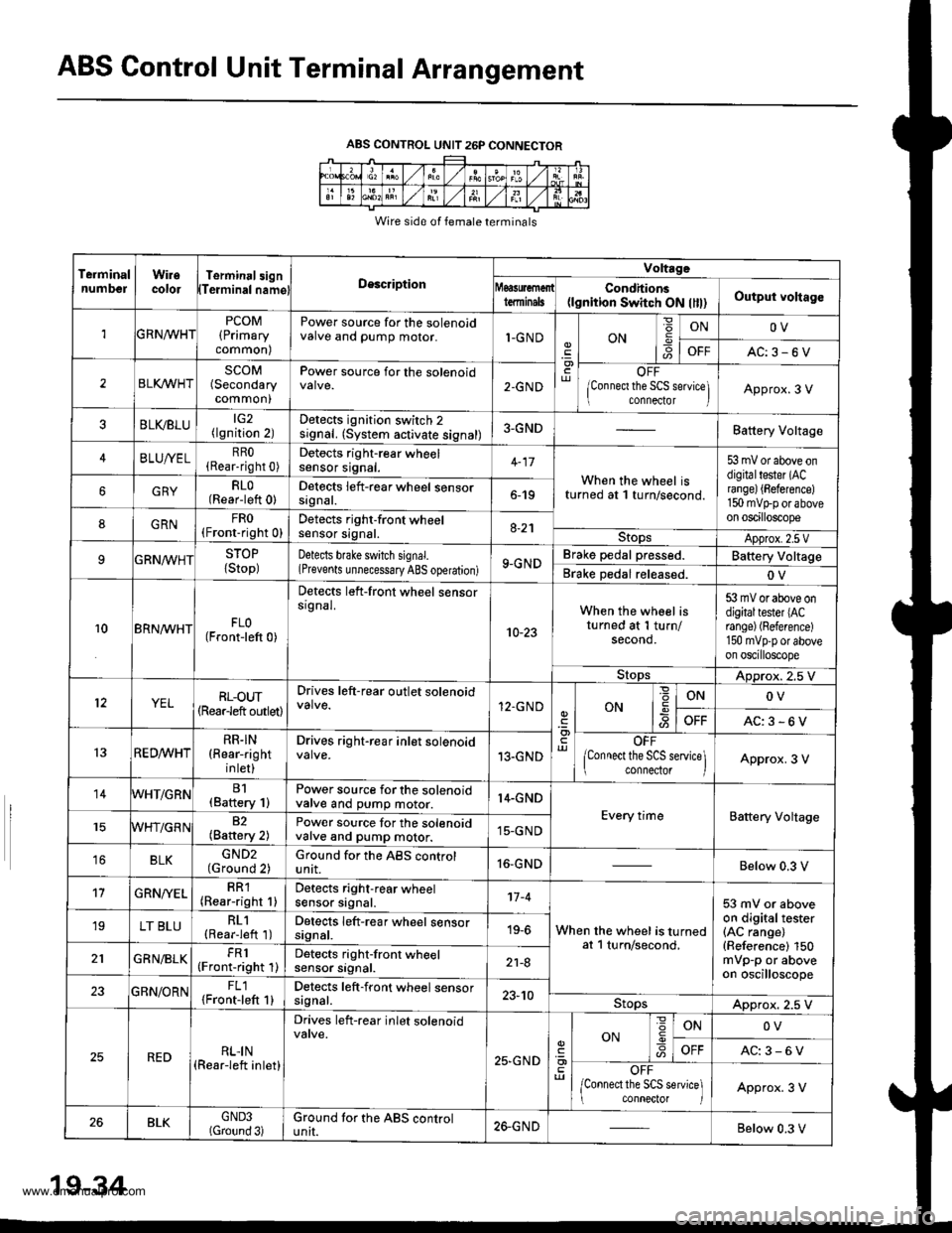
ABS Control Unit Terminal Arrangement
ABS CONTROL UNIT 26P CONNECTOR
Wire side of female terminals
TeiminalnumbelWiiecolorTerminal3ignTeiminalnamglDescription
Voltrge
tdminalsCondhions(lgnition Switch ON llll)Output voltago
1GRNn/VHTPCOM(Primary
common)
Power source for the solenoidvalve and pump motor.1-GNDON6
ONOV
OFFAC:3-6V
2BLI(WHTSCOM(Secondary
common)
Power source for the solenoid2-GNDOFF
lConnect the SCS seNice] connector IApprox.3 V
BLVBLU(lgnition 2)Detects ignition switch 2signal. (System activate signal)3-GNDBattery Voltage
4BLUA/ELRRO(Rear-right 0)Detocts right-rear wheelsensor srgnat.When the wheel isturned at 1 turn/second.
53 mV or above ondigitaltester (ACrange) {Beference)150 mvtrp or aboveon oscilloscope
GRYRLO(Rear-left 0)Detects left-rear wheel sensorsrgnat.6-19
8GRNFRO(Fronr-right 0)Detects right-front wheelsensor signal.8-21StopsApprox.2.5 VSTOP
{Stop)Detects bfake switch signal.(Prevents unnecessary ABS operation)9-GNDBrake pedal pressed.Battery Voltage
Brake Dedal released.OV
10BRN^/VHTFLO(Front-left 0)
Detects left-front wheel sensorsrgnal.
10-23
When the wheel isturned at 1 turn/second.
53 mV or above ondigitaltester lACrange) (Reference)
150 mvpp or aboveon oscilloscope
StopsADprox. 2.5 V
YELRL-oUT(Rearleft outlet)
Drives left-rear outlet solenoid12.GNDONONOV
OFFAC:3-6V
13RED^/vHTRR.IN(Rear-right
inlet)
Drives right-rear inlet solenoid13.GNDOFF
lConnect the SCS service\ connector IApprox. 3 V
14WHT/GRNB1(Baftery 1)Power source for the solenoidvalve and pump motor.14.GND
Every timeBattery Voltage82(Battery 2)Power source for the solenoidvalve and pump motor.15-GND
16BLKGND2(Ground 2)Ground for the ABS controlunit.16-GNDBelow 0.3 V
't7GRN/YELRR1(Rear-right 1)Detects right-rear wheelsensor signal.'t7 -4
When the wheel is turnedat l turn/second,
53 mV or aboveon digitaltester(AC range)(Reference) 150mVp-p or aboveon oscilloscope
19LT BLURL1(Rearieft 1)Detects left-rear wheel sensorsignal.19-6
GRN/BLKFR1(Front-right 1)Detects right-front wheelsensor srgnat.21-8
23GBN/ORNFL1{Front-left 1}Detects left-front wheel sensorsagnal.23-10StopsApprox. 2.5 V
REDRLI N(Rear-left inlet)
Drives left-rear inlet solenoid
25,GND
ON
=
-9ONOV
AC:3-6V
OFF
/Connect the SCS service] conneclor IApprox. 3 V
26BLKGND3(Gtound 3)Ground tor the ABS controluntI.26-GNDBelow 0.3 V
19-34
www.emanualpro.com
Page 958 of 1395
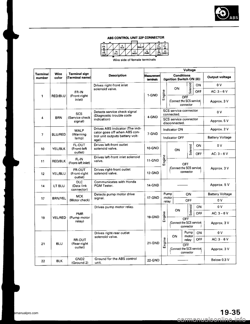
ABS CONTROL UNIT 22P CONNECIOR
Wire side ol lemale terminals
TerminalnumDerWirecolorTerminal 3i9nTerminal nameDescription
Voltage
Conditions(lgnition Switch ON (ll)lOutput voltagetominals
1RED/BLUFR-IN(Front-right
inlet)
Drives right-front inletsolenoid valve.
1-GND.9otur
ONIONOV
OFFAC:3-6V
OFF
lconnect the SCS servicel
connedor lApprox.3 V
BRN(Service checksignal)
Detects service check signal(Diagnostic trouble codeindication)4.GND
SCS service connectorconnected.OV
SCS service connectordisconnected.Approx. S V
7BLU/RED(Warning
ramp)
Drives ABS indicator {The indi-
cator goes off when ABS con-
trol unit outputs battery volt-age).
7.GND
lndicator ONApprox. 2 V
lndicator OFFBattery Voltage
10YEUBLKFL-OUT(Frontieft
outlet)
Drives left-front outletsolenoid valve.1O-GNDON
=
I
ONOV
OFFAC:3-6V
l'lRED/BLKFL-IN(Front-left inlet)
Drives left-front inlet solenoid11-GNDOFF
lconnect the SCS servicq connector lApprox.3 V
YEUBLUFR-OUT(Front-right
outlet)
Drives right-front outletsolenoid valve.12-GND
14LT BLU(Data linkconnectod
Communicates with HondaPGM Tester.14-GNDApprox. 5 V
17BRN/YELMCK(Motor check)
Detects PumP motor drivesignal.17-GNDPumpmotorrelay
ONBattery Vollage
OFFOV
19YEUREDPMR(Pump motorreray,
Drives pump motor relay.
19.GNDcl)
ON6IONOV
OFFAC:3-6V
OFFponnecl the SCS service]
connector IApprox.3 V
BLURR-OUT(Rear-right
outlet)
Drives right-rear outletsolenoid valve.
21.GND'a)
ONPumpmororrcray
ONOV
OFFAC:3 6V
OFF
lconnect the SCS service] connector lApprox.3 V
BLKGND2(Ground 2)Ground for the ABS controlunit.22.GNDBelow 0.3 V
19-35
www.emanualpro.com
Page 959 of 1395
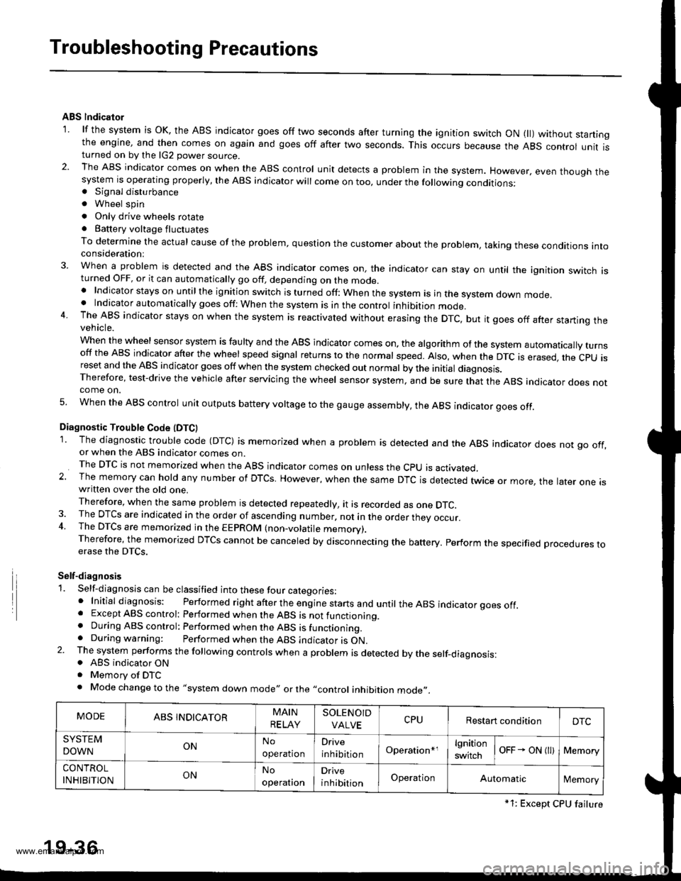
Troubleshooting Precautions
ABS lndicalor
1 lf the system is oK, the ABS indicator goes off two seconds after turning the ignition switch oN 1l) wathout staningthe engine, and then comes on again and goes off after two seconds. This occurs because the ABS control unit isturned on by the lG2 power source.2. The ABS indicator comes on when the ABS control unit detects a problem in the system. However, even thouoh thesystem is operating properly, the ABs indicator will come on too, under the following conditions:. Signal disturbance
. Wheel spin
. Only drive wheels rotate. Battery voltage fluctuates
To determine the actual cause of the problem, question the customer about the problem, taking these conditions intoconsideration:
3 When a problem is detected and the ABS indicator comes on, the indicator can stay on until the ignition switch isturned OFF, or it can automatically go off, depending on the mode.. Indicator stays on untilthe ignition switch is turned off: When the system is in the system down mode.. Indicator automatically goes off: When the system is in the control inhibition mode.4 The ABS indicator stays on when the system is reactivated without erasing the DTC, but it goes off after starting thevehicle.
When the wheel sensor system is faulty and the ABS indicator comes on. the algorithm of the system automatically turnsoff the ABS indicator after the wheel speed signal returns to the normal speed. Also, when the DTc is erased, the cpu isreset and the ABS indicator goes off when the system checked out normal by the initial diagnosis.Therefore, test-drive the vehicle after servicing the wheel sensor system. and be sure that the ABS indicator does notcome on.
5 When the ABS control unit outputs battery voltage to the gauge assembly, the ABS indicator ooes off.
Diagnostic Trouble Code (DTCI
1. The diagnostic trouble code (DTc) is memorized when a problem is detected and the ABS indicator does not go off,or when the ABS indicator comes on.The DTc is not memorized when the ABS indicator comes on unress the cpu is activated,2 The memory can hold any number of DTCs. However, when the same DTc is detected twice or more, the tater one iswritten over the old one.
Therefore, when the same problem is detected repeatedly, it is recorded as one DTC.3. The DTCs are indicated in the order of ascending number, not in the order they occur.4. The DTCS are memorized in the EEPROM (non-volatile memorv).Therefore, the memorized DTcs cannot be canceled by disconnecting the battery. perform the specified procedures toerase the DTCS.
Self-diagnosis
1. Self-diagnosis can be classified into these four categories:' Initial diagnosis: Performed right after the eng ine starts and untir theABS indicator goes off.. Except ABS control: Performed when the ABS is not functioning.. During ABS control: Performed when the ABS is functioning.. During warning: Performed when the ABS indicator is ON.2. The system performs the fo|owing contrors when a probrem is detected by the serf-diagnosis:. ABS indicator ON. Memorv of DTC. Mode changetothe "system down mode,, or the ,,control inhibition mode,,.
MODEABS INDICATORMAIN
RELAY
SOLENOID
VALVECPURestart conditionDTC
SYSTEM
DOWNONNo
operation
Drive
inhibitionOperation*rlgnition
switchoFF - ON l)Memory
CONTROL
INHIBITIONONNo
operal|on
Drive
inhibitionOperationAutomaticlMemory
*1: Except CPU failure
19-36
www.emanualpro.com
Page 960 of 1395
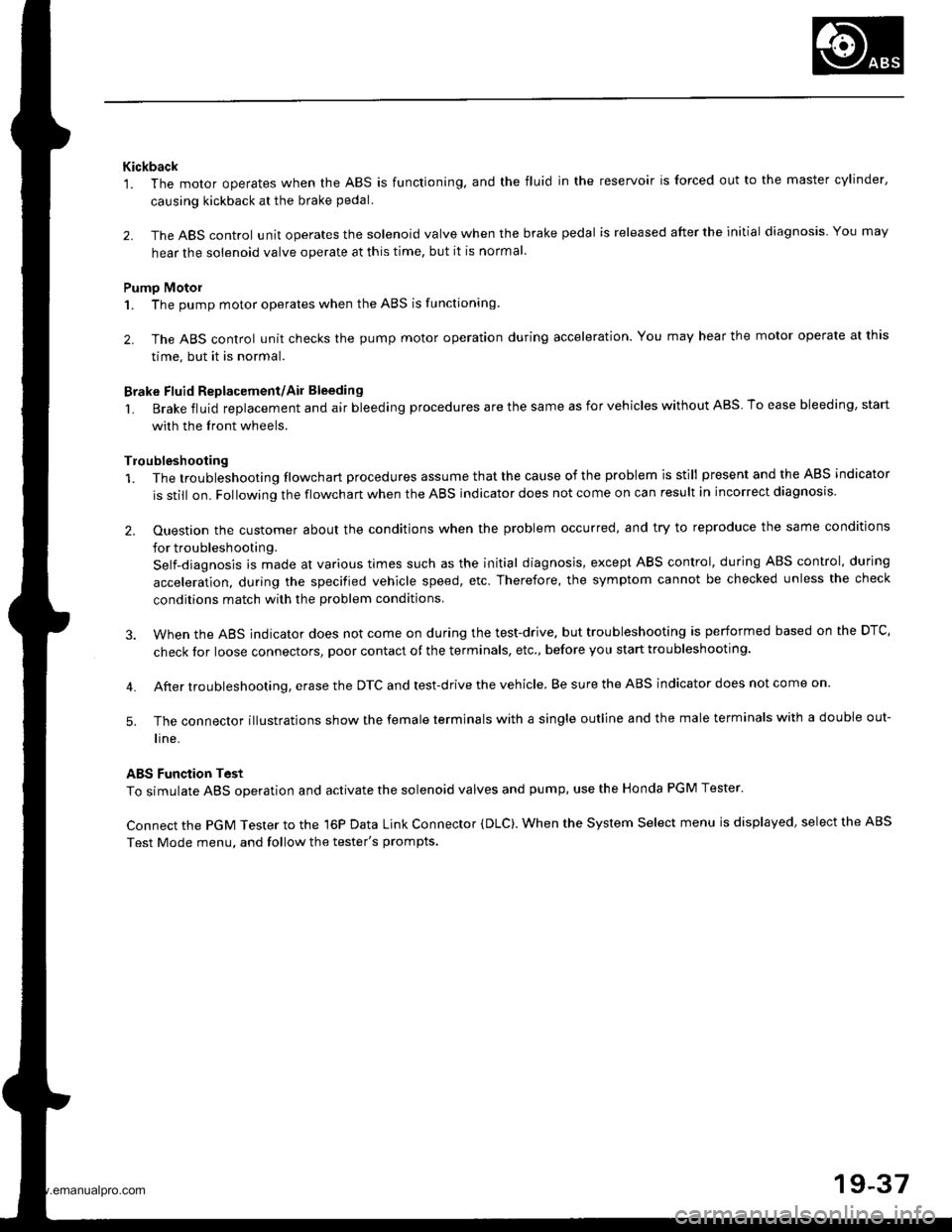
Kickback'1. The motor operates when the ABS is functioning. and the fluid in the reservoir is forced out to the master cylinder,
causing kickback at the brake pedal.
2. The ABS control unit operates the solenoid valve when the brake pedal is released after the initial diagnosis You may
hear the solenoid valve operate at this time, but it is normal
Pumo Motol
1. The pump motor operates when the ABS is functioning
2. The ABS control unit checks the pump motor operation during acceleration. You may hear the motor operate at this
time, but it is normal.
Brake Fluid Replacement/Ail Bleeding
L Brake fluid replacement and air bleeding procedures are the same as for vehicles without ABS To ease bleeding, start
with the front wheels.
Troubleshooting
1. The troubleshooting flowchart procedures assume that the cause of the problem is still present and the ABS indicator
is still on. Following the flowchart when the ABS indicator does not come on can result in incorrect diagnosis.
2. Ouestion the customer about the conditions when the problem occurred, and try to reproduce the same conditions
for troubleshooting.
Self-diagnosis is made at various times such as the initial diagnosis, except ABS control, during ABS control, during
acceleration, during the specified vehicle speed, etc. Therefore, the symptom canngt be checked unless the check
conditions match with the problem conditjons
3. When the ABS jndicator does not come on during the test-drive. but troubleshooting is performed based on the DTC,
check lor loose connectors, poor contact of the terminals, etc., before you start troubleshooting.
4. After troubleshooting, erase the DTC and test-drive the vehicle. Be sure the ABS indicator does not come on.
5. The connector illustratjons show the female terminals with a single outline and the male terminals with a double out-
l ne.
ABS Function Test
To simulate ABS operation and activate the solenoid valves and pump, use the Honda PGM Tester.
Connect the PGM Tester to the 16P Data Link Connector (DLC). When the System Select menu is displayed, select the ABS
Test Mode menu, and follow the tester's prompts.
19-37
www.emanualpro.com
Page 1091 of 1395
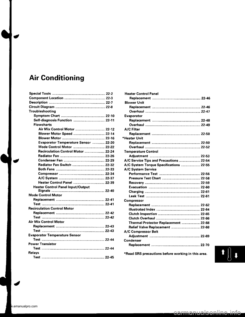
Air Conditioning
Heater Control Panel
Reofacement ,.,...,,.,..,.,.,,22-46
Blower Unit
Replacement .................. 22-46
Overhaul ...........,,,., .......-.22-17
Evaporalor
ReDlacement ...,.,.,..,......,22-4A
Overhaul ................ .........22-19
A/C Filter
Replacement ..................22-50*Heater Unit
ReDfacement ..................22-50
Overhaul ..,.,..,.,...,.. .........22-52
Temperature Control
Adiustment ....................22-53
A/C Service Tips and Precauiions............-....-.... 22-54
A/C System Torque Specifications .................... 22-55
A/C System Service
Performance Test ......,...22-56
Pressure Test Chart .-.....22-5a
Recovery ..............,. ...-.-...22-59
Evacuation -...........-........22-60
Charging ................ .......-.22-61
Leak Test ........................22-61
Compressor
Repfacement ..........-.......22-62
flfustrated Index .....,.......22-64
Cfutch fnspection .........,.22-65
Cfutch Overhaul ............- 22-66
Thermaf Protector Rep|acement ................... 22-68
Refief Valve Replacement .............................. 22-68
A/C Comoressor Belt
Adiustment .................... 22-69
Condenser
Repfacement .,.....,,.,..,.,..22-70
'Read SRS precautions betore working in this area.
www.emanualpro.com
Page 1093 of 1395
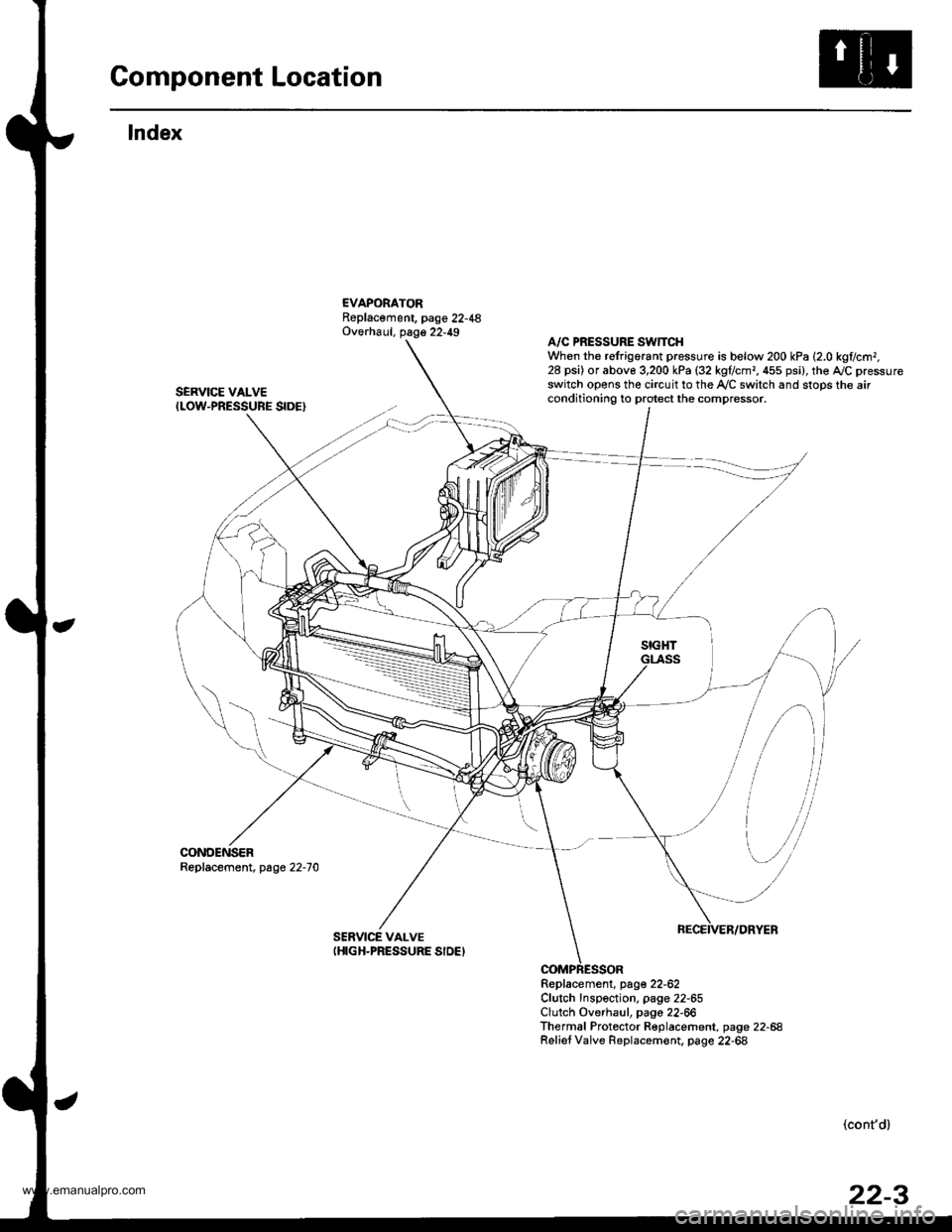
Component Location
lndex
EVAPORATORReplacement, page 22-48Overhaul, page 22-49
SERVICE VALVEILOW-PRESSURE SIDE}
CONDENSERReplacement, page 22-70
A/C PRESSURE SWTTCHWhen the refrigorant pressure is below 200 kPa 12.0 kglc.r|r,28 psi) or abov€ 3,200 kPa (32 kgflcmr, 455 psi), the AJC pressureswitch opens the circuit to the Ay'C switch and stops the airconditioning to protect the compressor.
Replacement, page 22-62Clutch Inspection, page 22-65Clutch Overhaul, pago 22-66Thermal Protector Replacement, page 22-68Relief Valve Replacem€nt. page 22-68
SERVICE VALVEIHIGH-PRESSURE SIDEI
,
[\,
-il
(cont'd)
www.emanualpro.com
Page 1094 of 1395
Component Location
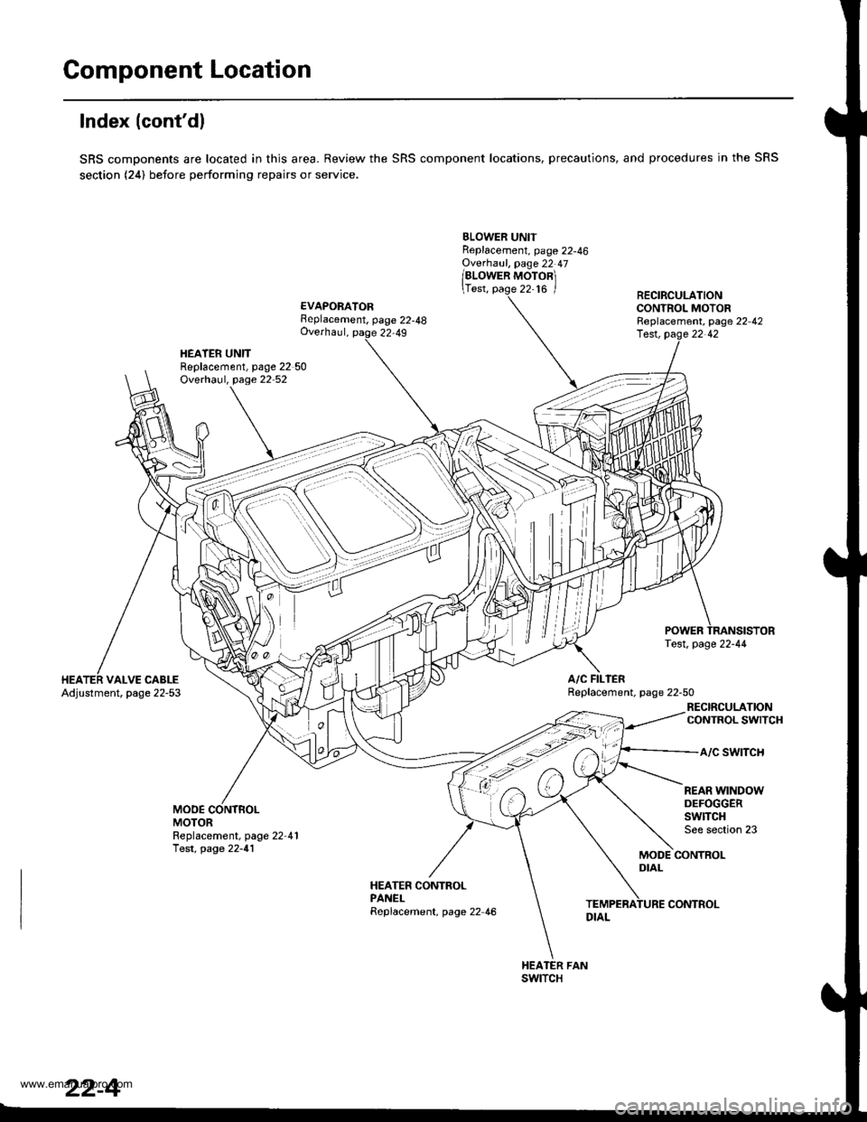
lndex (cont'dl
SRS components are located in this area. Review the SRS component locations, precautions, and procedures in the SRS
section (24) before performing repairs or service.
BLOWER UNITReplacement, page 22-46Ovethaul, page 22 47
/alowen ruoronl
\Test, page 22-16 /
EVAPORATORFeplacement, page 22-48Overhaul, page 22,49
RECIRCULATIONCONTROL MOTORReplacement, page 22 42
HEATER UNITReplacement, page 22 50Overhaul, page 22 52
lest, pag.e 22 42
A/C FILIERReplacement. page 22-50VALVE CABLEAdjustment, page 22-53
RECIRCULATIONCONTROL SWITCH
a/c swtTcH
MODEMOTOR
REAR WINDOWDEFOGGERSwlTCHSee section 23Replacement, page 22-41Test, page 22-41MODE CONTROLDIAL
HEATER CONTROLPANELReplacement, page 22 46
swtTcH
22-4
CONTROL
www.emanualpro.com
Page 1097 of 1395
Description
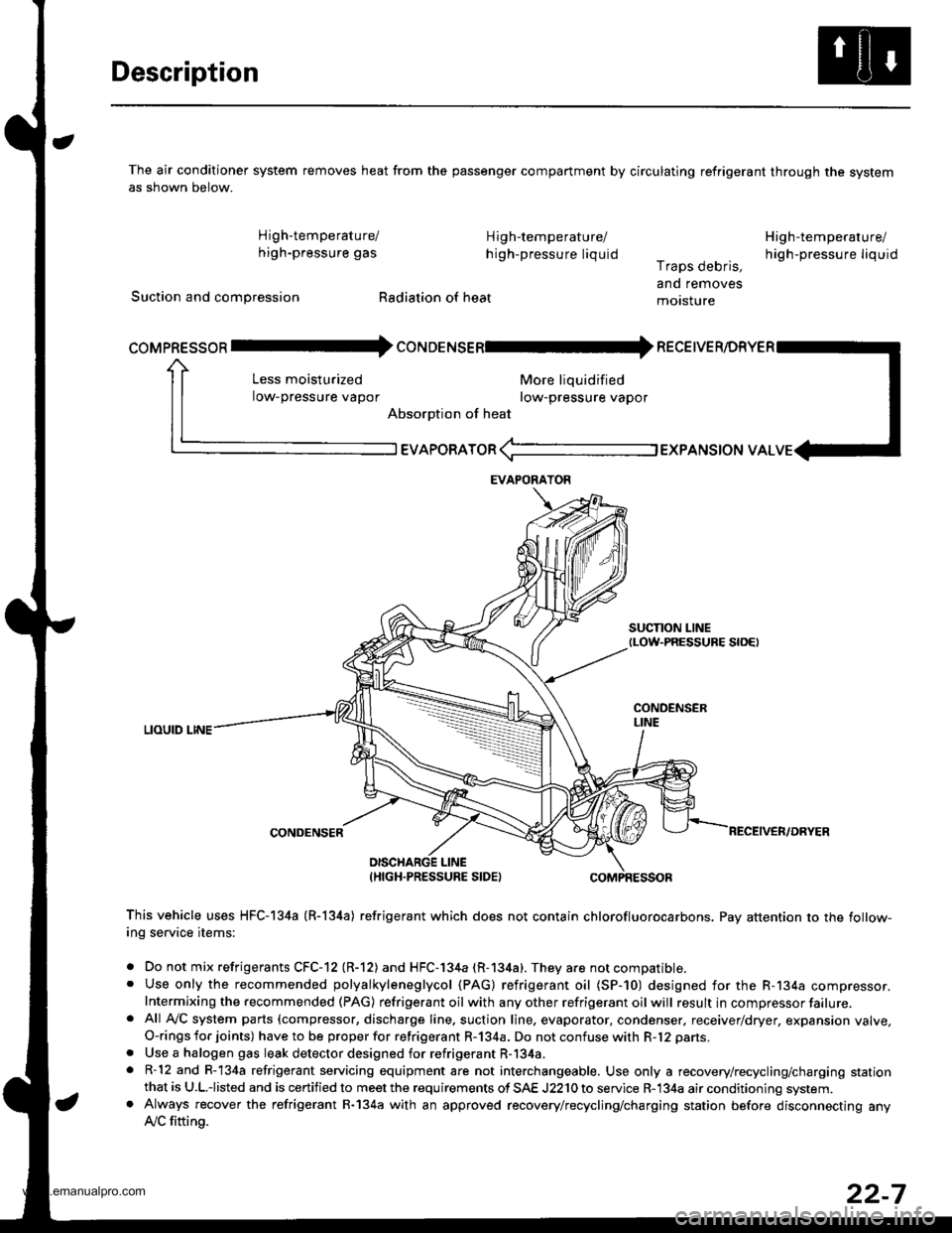
The air conditioner system removes heat from the passenger compartment by circulating refrigerant through the systemas shown below.
High'temperature/ High-temperature/
high-pressure gas h igh-pressure liquid
Suction and compression Radiation of heat
High-temperature/
high-pressu re liq uidr raps oeons,
and removes
motsture
More liquidified
row-pressure vapor
EVAPoRAToR (-l EXPANSToN vAL
SUCTION LINEtLow-PRESSURE S|OEt
LIOUID LINE
CONDENSER
coMpREssoR Il- coruoerusenl* necetve
Less moisturized
low-pressure vapor
Absorption of heat
DISCHARGE LINEIHIGH.PRESSURE SIDEI
This vehicle uses HFC-I34a (R-l34a) refrigerant which does not contain chlorofluorocarbons. Pay attention to the follow-ing service items:
. Do not mix refrigerants CFC-12 (R-12) and HFC-l34a (R-134a). They are not compatible.. Use only the recommended polyalkyleneglycol (PAG) refrigerant oil (SP-10) designed for the R-134a compressor.Intermixing the recommended (PAG) refrigerant oil with any other refrigerant oil will result in compressor failure.. Afl Ay'C system parts (compressor, discharge line. suction line, evaporator, condenser. receiver/dryer, expansion valve,O-rings for joints) have to be proper for refrigerant R-134a. Do not confuse with R-12 parts.
. Use a halogen gas leak detector designed for refrigerant R-134a.. R-12 and R-134a refrigerant servicing equipment are not interchangeable. Use only a recovery/recycling/charging stationthat is U.L.iisted and is certified to meet the requirements of SAE J2210 to service R-134a air conditioning system.. Always recover the refrigerant R-134a with an approved recovery/recycling/charging station before disconnecting anylVC fitting.
EVAPORAYOR
22-7
www.emanualpro.com
Page 1139 of 1395
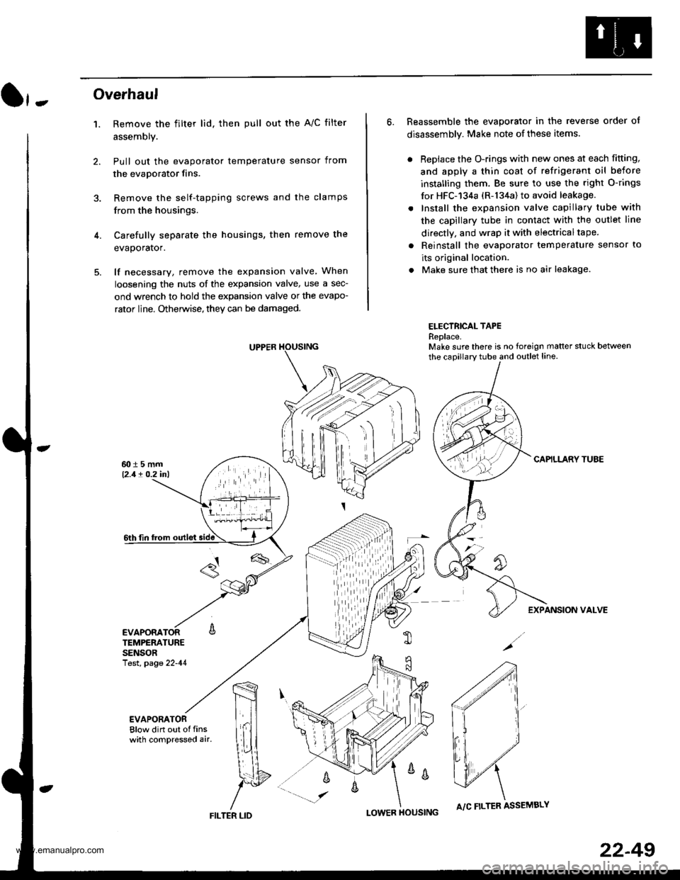
}-Overhaul
1. Remove the filter lid. then pull out the A/C filter
assembly.
Pull out the evaporator temperature sensor from
the evaporator fins.
Remove the self-tapping screws and the clamps
from the housings.
Carefully separate the housings, then remove the
evaporator.
lf necessary, remove the expansion valve When
loosening the nuts of the expansion valve, use a sec-
ond wrench to hold the expansion valve or the evapo-
rator line. Otherwise, they can be damaged.
6. Reassemble the evaporator in the reverse order of
disassembly. Make note of these items.
. Replace the O-rings with new ones at each fitting,
and apply a thin coat of refrigerant oil before
installing them. Be sure to use the right O-rings
for HFC-'134a (R-134a) to avoid leakage.
. Install the expansion valve capillary tube with
the capillary tube in contact with the outlet line
directly, and wrap it with electricaltape.
. Reinstall the evaporator temperature sensor to
its original location.
. Make sure that there is no air leakage.
ELECTRICAL TAPEReplace.Make sure there is no foreign matter stuck between
the capillary tube and outlet line.
CAPILLARY TUAE
EXPANSION VALVE
4.
TEMPERATURESENSORlest, page 22-41
,m
\!{
YFILTER LID
;
I-OWER HOUSINGA/C FILTER ASSEMBLY
22-49
www.emanualpro.com
Page 1140 of 1395
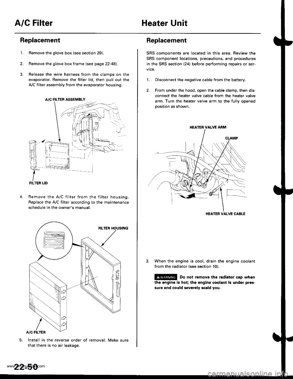
A/C FilterHeater Unit
Replacement
1.Remove the glove box (see section 20).
Remove the glove box frame {see page 22-4A).
Release the wire harness from the clamps on the
evaporator. Remove the filter lid, then pull out the
,VC filter assembly from the evaporator housing.
A/C FILTER ASSEMELY
Remove the A/C filter from the filter housing.
Replace the Ay'C filter according to the maintenance
schedule in the owner's manual.
Install in the reverse order of removal. Make sure
that there is no air leakage.
22-50
Replacement
SRS components are located in this area. Review the
SRS component locations, precautions, and procedures
in the SRS section {24) before performing repairs or ser-
1. Disconnect the negative cable from the battery.
2. From under the hood, open the cable clamp, then dis-
connect the heater valve cable from the heater valve
arm. Turn the heater valve arm to the fullv ooened
oosition as shown.
When the engine is cool, drain the engine coolant
from the radiator (see section 10).
@ Do not remove the rldiator cap when
the engine is hot; the engine coolant is under pres-
sure and could sevo.ely scald you.
HEATER VALVE ARM
HEATER VALVE CABLE
www.emanualpro.com