Valve HONDA CR-V 1999 RD1-RD3 / 1.G Workshop Manual
[x] Cancel search | Manufacturer: HONDA, Model Year: 1999, Model line: CR-V, Model: HONDA CR-V 1999 RD1-RD3 / 1.GPages: 1395, PDF Size: 35.62 MB
Page 873 of 1395
Power Steering Pump
Reassembly
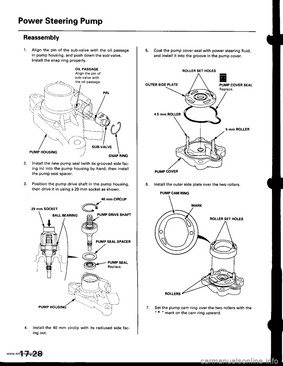
'1.Align the pin of the sub-valve with the oil passage
in pump housing, and push down the sub-valve.
Install the snsp ring properly.
OIL PASSAG€Align the pin of
the oil passage.
#q
;1..*
\SNAP RINGPUMP HOUSING
Install the new pump seal (with its grooved side fac-
ing in) into the pump housing by hand, then install
the pump seal spacer.
Position the pump drive shaft in the pump housing,
then drive it in using a 29 mm socket as shown,
BALL BEARfNG grlu,e un.t
/ /ffi\
1 / t\v4
t/ Y
# I F
PUMP SEALSPAC,ER
ry^
i- d
,O mm CIRCLIP
Hgo
/= PUMP DRIVE SHAFT
@.--#$i":*'
4,
PUMP HOUSING
Install the 40 mm circlip with its radiused side fac-
Ing out.
29 mm SOCKET
17 -2A
7.
5. Coat the pump cover seal with power steering fluid,
and install it into the groove in the pump cover.
OUTER SIDE PLATE
5 mrh ROLLER
lnstall the oute. side plate over the two rollers.
PUMP CAM RING
ROLLER SET HOLES
ROLLERS
Set the pump cam ring over the two rollers with the"' " mark on the cam ring upward.
ROLLER SET HOLES
PUMP COVER
www.emanualpro.com
Page 874 of 1395
8.
9.
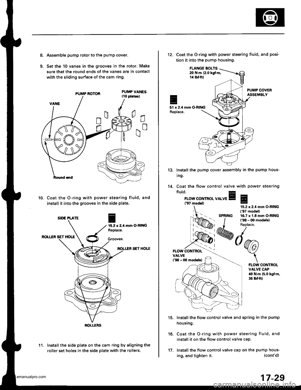
Asssmble pump rotor to the pump cover,
Set the 10 vanes in the grooves in the rotor, Make
sure that the round ends of the vanes are in contact
with the sliding surface of the cam ring.
PUMP ROTOR
Coat the O-ring with power steering fluid, and
install it into the grooves in the side plate.
ftm GRING
ROL1IR SET HOI,E
SET HOTT
Install the side plate on the cam ring by aligning the
roller set holes in the side Dlate with the rollers.
10.
I
15.2 x 2-1Replace.
Gfooves.
SII'E PLATE
BOLI-ERS
11.
17.
ing, and tighten it.
12. Coat the O-ring with power steering fluid,
tion it into the pump housing.
and posi-
FLANGE BOI-TS20 N.m (2.0 kgt m,14 tbf.ft)
51 x 2.4 mm O-RINGReplace.
13.
14.
lnstall the
ing.
Coat the
fluid.
pump cover assembly in the pump hous-
tlow control valve with power steering
FLOW CONTROL VALVE137 modol)
FLOW CONTBOLVALVEl'98 - 0O modeltl
'15.
16.
Install the flow control valve and spring in the pump
housing.
Coat the O-ring with power steering fluid, and
install it on the flow control valve cap.
Install the flow control valve cap on the pump hous-
Eg
SPRING
15.2 x 2.4 mm O.RING('97 modell16.7 x'1.8 mm O-RING
FLOW CONTROLVALVE CAP49 N.m (5.0 kgl.m,36 tbf.ft)
(cont'd)
17-29
www.emanualpro.com
Page 876 of 1395
Power Steering Gearbox
Removal
Note these items during removal:
. Using solvent and a brush, wash any oil and dirt off
the valve body unit its lines, and the end if the gear-
box. Blow dry with compressed air.
. Be sure to remove the steering wheel before discon-
necting the steering joint. Damage to the cable reel
can occur.
. With 4WD. tilt the engine with a jack to expand the
clearance between the transfer assembly and rear
beam when removing the steering gearbox from the
rear oeam.
Do not remove the steering gearbox by removing the
transfer assembly from the transmission.
1. Drain the power steering fluid as described on page'17-15.
Raise the vehicle, and suppon it on safety stands in
the proper locations (see section 1).
Remove the front wheels,
Remove the drive/s airbag assembly {see section 24).
Remove the steering wheel {see page 17-18).
Remove the steering joint bolts, then disconnect the
steering joint by moving the joint toward the column.
UPPER JOINT BOLT
LOWER JOINT BOLT
13.
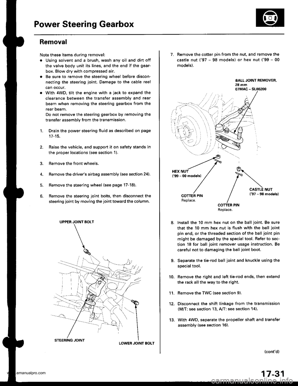
7. Remove the cotter pin from the nut, and remove the
castle nut {'97 - 98 models) or hex nut ('99 - 00
models).
COTTER PINReplace.
Install the 10 mm hex nut on the ball joint. Be sure
that the 10 mm hex nut is flush with the ball joint
pin end, or the threaded section of the ball joint pin
might be damaged by the special tool. Refer to sec-
tion 18 for ball joint remover usage instruction, Be
careful not to damaging the ball joint boot.
Separate the tie-rod ball joint and knuckle using the
special tool.
Remove the right and left tie-rod ends, then extend
the rack all the way to the right.
Remove the TWC (see section 9).
Disconnect the shift linkage from the transmission
(M/T: see section 13, A/T: see section 14).
With 4WD. separate the propeller shaft and transfer
assembly (see section 161.
10.
11.
(cont'd)
17-31
www.emanualpro.com
Page 877 of 1395
Power Steering Gearbox
AN'USTABLE HOSE CLAMP
Removal (cont'dl
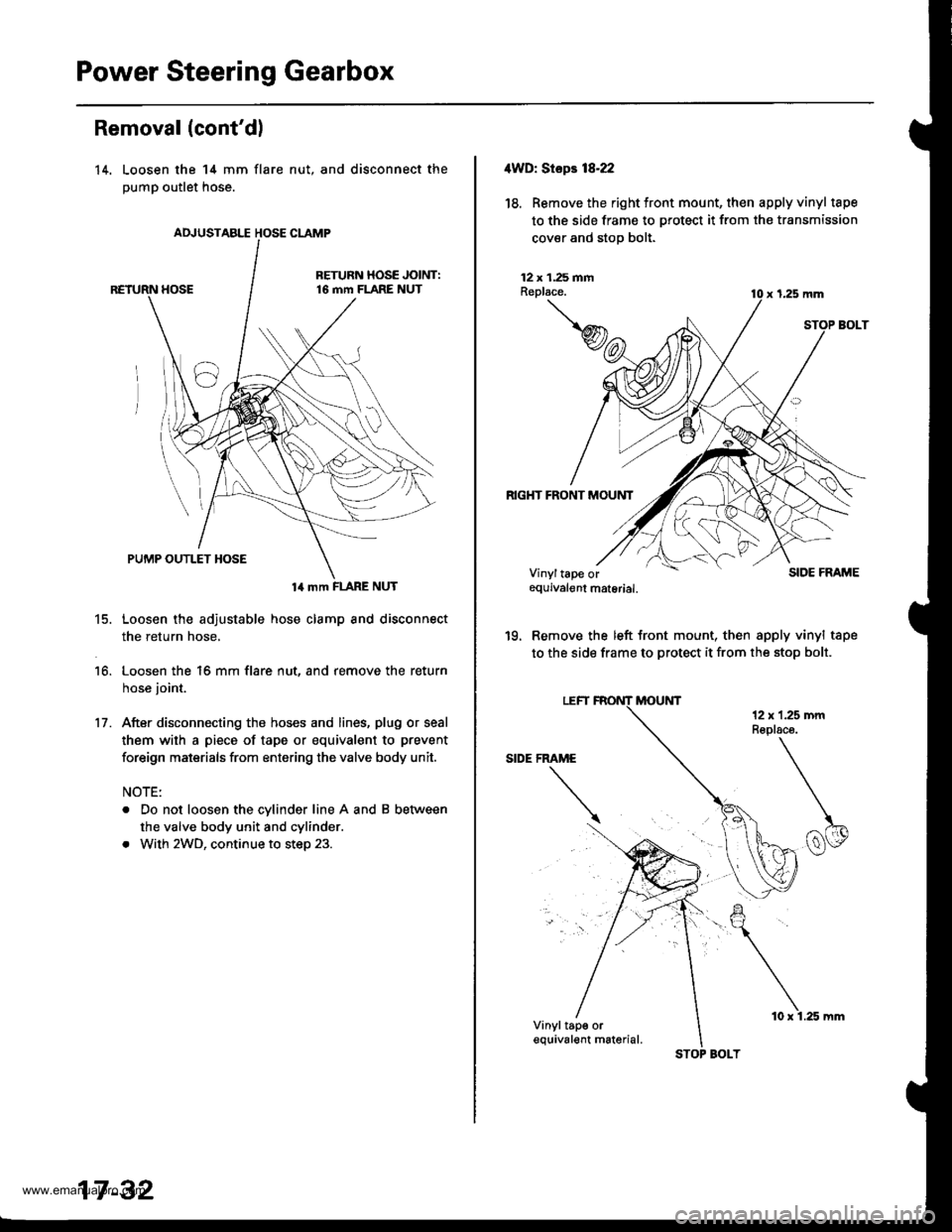
14. Loosen the 14 mm flare
pump outlet hose.
nut, and disconnect the
14 mm FLARE NUT
15. Loosen the adjustable hose clamp and disconnect
the return hose,
16. Loosen the 16 mm flare nut, and remove the return
hose joint.
17. After disconnecting the hoses and lines, plug or seal
them with a piece of tape or equivalent to prevent
foreign maisrials from entering the valve body unit.
NOTE:
. Do not loosen the cylinder line A and B between
the valve body unit and cylinder.
. With 2WD, continue to step 23.
17 -32
STOP BOLT
10 x 1.25 mm
4WD: Stepr 18-22
18. Removethe right tront mount, then apply vinyl tape
to the side frame to protect it from the transmission
cover and stop bolt.
12 x 1.25 fiiAReplace.
RIGHT FRONT MOUNT
x 1,25 mm
SIDE FRAME
'19. Remove the left front mount, then apply vinyl tape
to the side frame to protect it from the stop bolt.
Vinyltape orequivalgnt material.
Vinyltap€ orequival€nt m6terial.
www.emanualpro.com
Page 880 of 1395
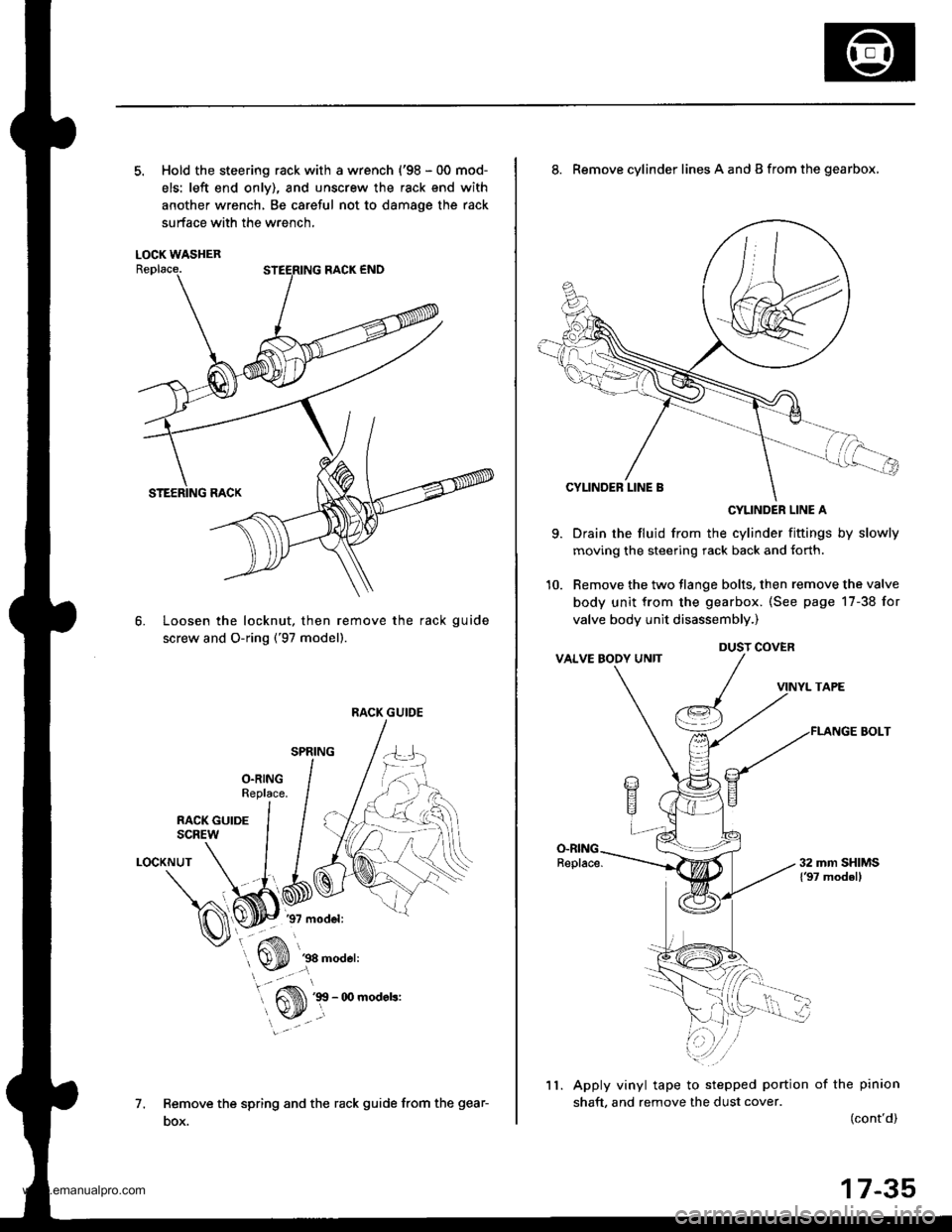
5. Hold the steering rack with a wrench {'98 - 00 mod-
els: left end onlv), and unscrew the rack end with
another wrench, Be careful not to damage the rack
surface with the wrench,
LOCK WASHER
Loosen the locknut, then remove the rack guide
screw and O-ring ('97 model).
6.
1.
LOCKNUT
Remove the spring and the rack guide from the gear-
DOX.
RACK GUIDE
9.
8. Remove cylinder lines A and B from the gearbox,
CYLINDER LINE A
Drain the fluid from the cylinder fittings by slowly
moving the steering rack back and {orth.
Remove the two tlange bolts, then remove the valve
body unit from the gearbox. (See page 17-38 for
valve body unit disassembly.)
VINYL TAPE
FLANGE BOLT
Apply vinyl tape to stepped portion of the pinion
shaft, and remove the dust cover.(cont'd)
DUST COVER
11.
17-35
www.emanualpro.com
Page 883 of 1395
Power Steering Gearbox
Disassembly (cont'd)
Valve Body Unit Dbassembly
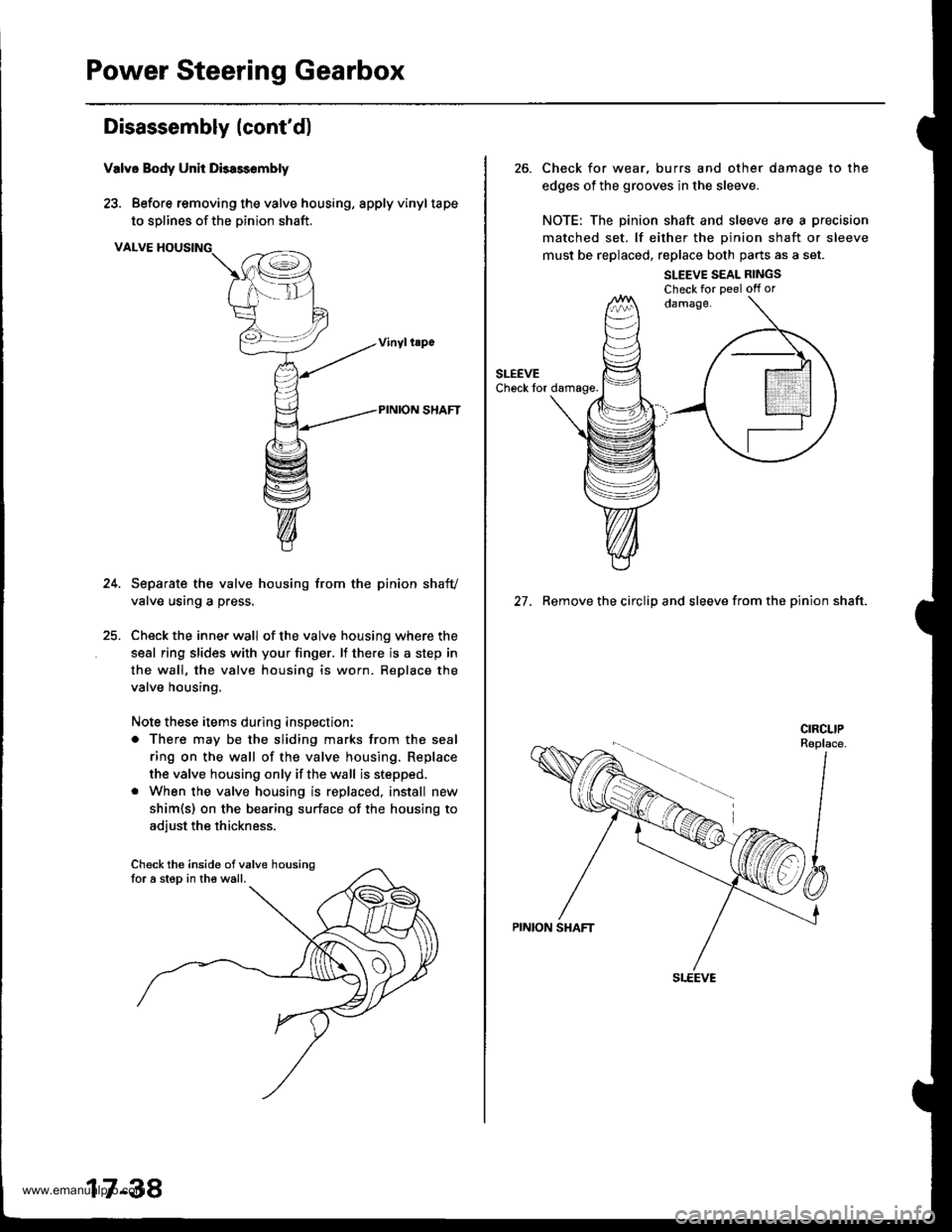
23. Before removing the valve housing, apply vinyltape
to solines of the Dinion shaft.
VALVE HOUSING
Separate the valve housing from the pinion shafv
valve using a press.
Check the inner wall of the valve housing where the
seal ring slides with your finger. lf there is a step in
the wall, the valve housing is worn. Replace the
valve housing.
Note these items during inspection:
o There may be the sliding marks from the seal
ring on the wall of the valve housing. Replace
the valve housing only if the wall is stepped.
. When the valve housing is replaced, install new
shim{s) on the bearing surface of the housing to
adiust the thickness.
Check the inside ofvalve housingfor a step in the wall.
17-38
26. Check for wear, burrs and other damage to the
edges of the grooves in the sleeve.
NOTE: The pinion shaft and sleeve are a precision
matched set. lf either the oinion shaft or sleeve
must be replaced, replace both parts as a set.
SLEEVE SEAL RINGSCheck for Deel off or
27. Remove the circlip and sleeve from the pinion shaft.
www.emanualpro.com
Page 884 of 1395
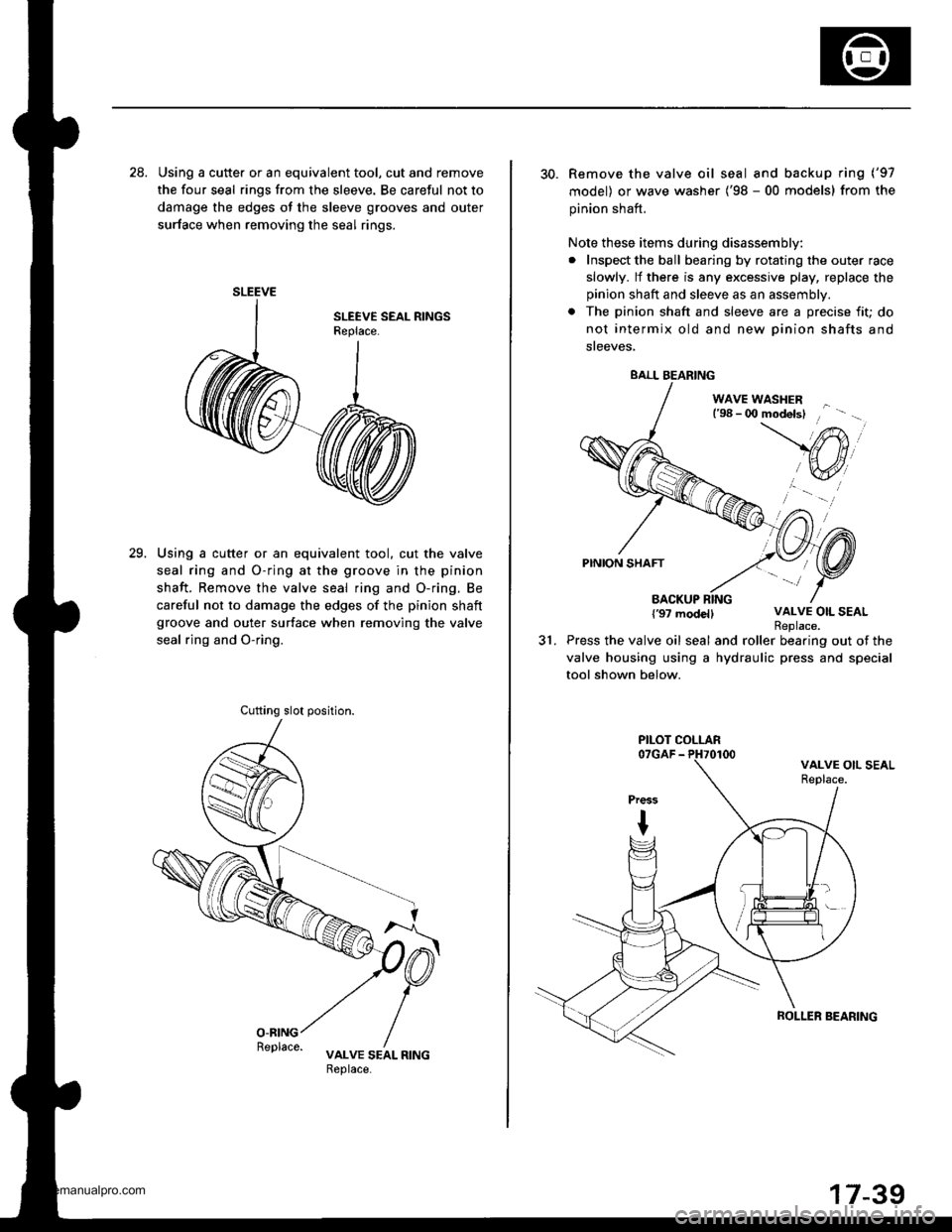
28. Using a cutte. or an equivalent tool, cut and remove
the four seal rings from the sleeve. Be careful not to
damage the edges ot the sleeve grooves and outer
surface when removing the seal rings.
Using a cutter or an equivalent tool. cut the valve
seal ring and O-ring at the groove in the pinion
shaft. Remove the valve seal ring and O-ring. Be
careful not to damage the edges of the pinion shaft
groove and outer surface when removing the valve
seal rjng and O-ring.
29.
SLEEVE
Cufting slot position.
30. Remove the valve oil seal and backup ring ('97
model) or wave washer ('98 - 00 models) from the
pinion shaft.
Note these items during disassembly:
. Inspect the ball bearing by rotating the outer race
slowly. lf there is any excessive play, replace the
pinion shaft and sleeve as an assembly.
. The pinion shaft and sleeve are a precise fit; do
not intermix old and new Dinion shafts and
sreeves,
WAVE WASHERl'98 - 0O modelsl
PINION SHAFT
BACKUP RING{'97 modellVALVE OIL SEAL
31.Replace.Press the valve oil seal and roller bearing out of the
valve housing using a hydraulic press and special
tool shown below.
BALL BEARING
PILOT COLLAR
ROLLER SEARING
www.emanualpro.com
Page 885 of 1395
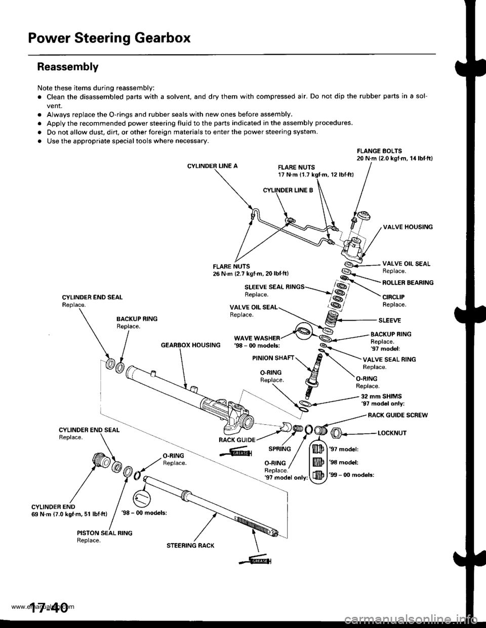
Power Steering Gearbox
Reassembly
Note these items during reassembly
. Clean the disassembled parts with a solvent, and dry them with compressed air. Do not dip the rubber parts in a sol-
vent.
. Always replace the O-rings and rubber seals with new ones before assembly.
. Apply the recommended power steering fluid to the parts indicated in the assembly procedures.
. Do not allow dust. dirt, or other toreign materials to enter the power steering system.
. Use the appropriate specialtools where necessary.
FLANGE BOLTS20 N.m (2.0 kgl.m, 14lbtftl
CYLINDER LINE AFLARE NUTS17 N.m 11.712 rbl.ftl
VALVE HOUSING
CYLINDER END SEALReplace.
VALVE OIL SEALBeplace.
ROLLER BEARING
CIRCLIPReplace.
BA.KUP RING
\/^"
WAVE WASHERBACKUP RINGReplace.97 model:HOUSING
VALVE SEAL RINGReplace.
O.RINGReplace.
32 mm SHIMS'97 mod6l only:
RACK GUIDE SCREW
O-RINGReplace.
@---r-ocxr'rur
'97 model:
'98 model:
'99 - 0O mod6ls:'9? model only:
CYLINDER END69 N.m (7.0 kgf.m, 51 lbf.ft)'98 - (x) models:
PISTON SEAL RINGReplace.
17-40
STEERING RACK
www.emanualpro.com
Page 886 of 1395
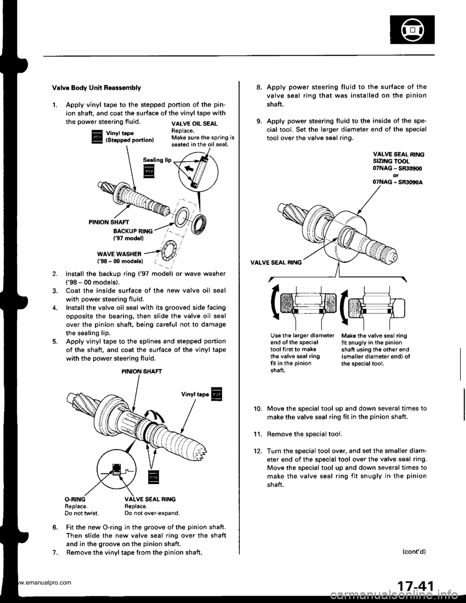
Valve Body Unh Roa$embly
1. Apply vinyl tape to the stepped portion of the pin-
ion shaft, and coat the surface of the vinyl tape with
the power steering fluid.
Vinyl tape(Stopp6d portion)
VALVE OIL SEALReplace.Make sure the spring isseated in the oil seal.
Serling
E
7.
PINION SHAFT
BACKUP RING137 modell
WAVE WASHER{'98 - 00 modelsl
Install the backup ring {'97 model) or wave washer
('98 - 00 models).
Coat the inside surface of the new valve oil seal
with power steering fluid.
Install the valve oil seal with its grooved side facing
opposite the bearing, then slide the valve oil seal
over the pinion shaft, being careful not to damage
the sealing lip.
Apply vinyl tape to the splines and stepped ponion
of the shaft, and coat the surface of the vinyl tape
with the power steering fluid.
Vinyl trp€
O.RINGReplace.Do not twist.R€place-Do not over-expand.
Fit the new O-ring in the groove of the pinion shaft.
Then slide the new valve seal ring over the shaft
and in the groove on the pinion shaft,
Remove the vinyl tape from the pinion shaft.
\/
PINION SHAFT
8.Apply power steering fluid to the surface of the
valve seal ring that was installed on the pinion
shaft.
Apply power steering fluid to the inside of the spe-
cial tool. Set the larger diameter end of the special
tool over the valve seal ring.
VALVE SEAL RINGSIZNG TOOL07NAG - SR309q'ot07NAG - SR3oltoA
Mak€ the valve seal ringfit snugly in the pinion
shatt using th6 other end{smaller diameter end) otthe special tool.
10.
11.
12.
Move the special tool up and down several times to
make the valve seal ring fit in the pinion shaft,
Remove the soecial tool.
Turn the special tool over, and set the smaller diam-
eter end of the specisl tool over the valve seal ring.
Move the special tool up and down several times to
make the valve seal ring fit snugly in the pinion
shaft.
(cont'd)
lrr.rj1
tffifrE-rr.]
r\-''] 7
Usg th6 larg€r diameterend of the specialtoollirst to maketh€ valve seal ringtit in the pinion
shaft.
17-41
www.emanualpro.com
Page 887 of 1395
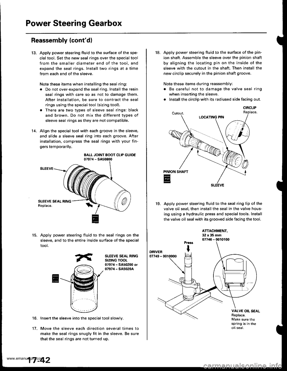
Power Steering Gearbox
13.
Reassembly (cont'd)
Apply power steering fluid to the surface of the spe-
cial tool. Set the new seal rings over the special tool
from the smaller diameter end of the tool. and
expand the seal rings. Install two rings at a time
Jrom each end ofthe sleeve.
Note these items when installing the seal ring:
. Do not over-expand the seal ring. Install the resin
seal rings with care so as not to damage them.
After installation, be sure to contract the seal
rings using the specialtool {sizing tool).
. There are two types of sleeve seal rings: black
and brown. Do not mix the different types of
sleeve seal rings as they are not compatible.
Align the special tool with each groove in the sleeve,
and slide a sleeve seal ring into each groove. After
installation, compress the seal rings with your fin-
gers temporarily.
BALL JOINT BOOT CLIP GUIDE07974 - SA508q)
SLEEVE
Apply power steering fluid to the seal rings on the
sleeve, and to the ehtire inside surface of the special
tool.
14.
15.
SLEEVE SEAL RINGSIZING TOOL07974 - SA502O0 or07974 - SA5020A
16.Insert the sleeve into the special tool slowly.
Move the sleeve each direction several times to
make the seal rings snugly fit in the sleeve. Be sure
that the seal rings are not turned up,
't1.
18. Apply power steering fluid to the surface of the pin-
ion shaft. Assemble the sleeve over the Dinion shaft
by aligning the locating pin on the inside of the
sleeve with the cutout in the shaft. Then install the
new circlip securely in the pinion shaft groove.
Note these items during reassembly:
. Be caretul not to damage the valve seal ring
when inserting the sleeve.
. Install the circlip with its radiused side facing out.
Apply power steering fluid to the seal ring lip of the
valve oil seal. then install the seal in the valve hous-
ing using a hydraulic press and special tools. Install
the valve oil seal with its grooved side facing the tool.
19.
ATTACHMENT,32x35mm077i16 - (x)10100
VALVE OIL SEALReplace.Make sure thespring is in theoilseal.
CIRCLIP
www.emanualpro.com