line HONDA CR-V 1999 RD1-RD3 / 1.G Workshop Manual
[x] Cancel search | Manufacturer: HONDA, Model Year: 1999, Model line: CR-V, Model: HONDA CR-V 1999 RD1-RD3 / 1.GPages: 1395, PDF Size: 35.62 MB
Page 960 of 1395
Kickback'1. The motor operates when the ABS is functioning. and the fluid in the reservoir is forced out to the master cylinder,
causing kickback at the brake pedal.
2. The ABS control unit operates the solenoid valve when the brake pedal is released after the initial diagnosis You may
hear the solenoid valve operate at this time, but it is normal
Pumo Motol
1. The pump motor operates when the ABS is functioning
2. The ABS control unit checks the pump motor operation during acceleration. You may hear the motor operate at this
time, but it is normal.
Brake Fluid Replacement/Ail Bleeding
L Brake fluid replacement and air bleeding procedures are the same as for vehicles without ABS To ease bleeding, start
with the front wheels.
Troubleshooting
1. The troubleshooting flowchart procedures assume that the cause of the problem is still present and the ABS indicator
is still on. Following the flowchart when the ABS indicator does not come on can result in incorrect diagnosis.
2. Ouestion the customer about the conditions when the problem occurred, and try to reproduce the same conditions
for troubleshooting.
Self-diagnosis is made at various times such as the initial diagnosis, except ABS control, during ABS control, during
acceleration, during the specified vehicle speed, etc. Therefore, the symptom canngt be checked unless the check
conditions match with the problem conditjons
3. When the ABS jndicator does not come on during the test-drive. but troubleshooting is performed based on the DTC,
check lor loose connectors, poor contact of the terminals, etc., before you start troubleshooting.
4. After troubleshooting, erase the DTC and test-drive the vehicle. Be sure the ABS indicator does not come on.
5. The connector illustratjons show the female terminals with a single outline and the male terminals with a double out-
l ne.
ABS Function Test
To simulate ABS operation and activate the solenoid valves and pump, use the Honda PGM Tester.
Connect the PGM Tester to the 16P Data Link Connector (DLC). When the System Select menu is displayed, select the ABS
Test Mode menu, and follow the tester's prompts.
19-37
www.emanualpro.com
Page 979 of 1395
Modulator Unit
Removal/lnstallation
NOTE:
. Do not spill brake fluid on the vehicle; it may damage the painu if brake fluid does contact the paint, wash it off imme-
diately with water.
a Take care not to damage or deform the brake lines during removal and installation.
. To prevent the brakefluidfrom flowing, plug and coverthe hose ends and joints with a shop towel or equivalent mate-
rial,
Romoval
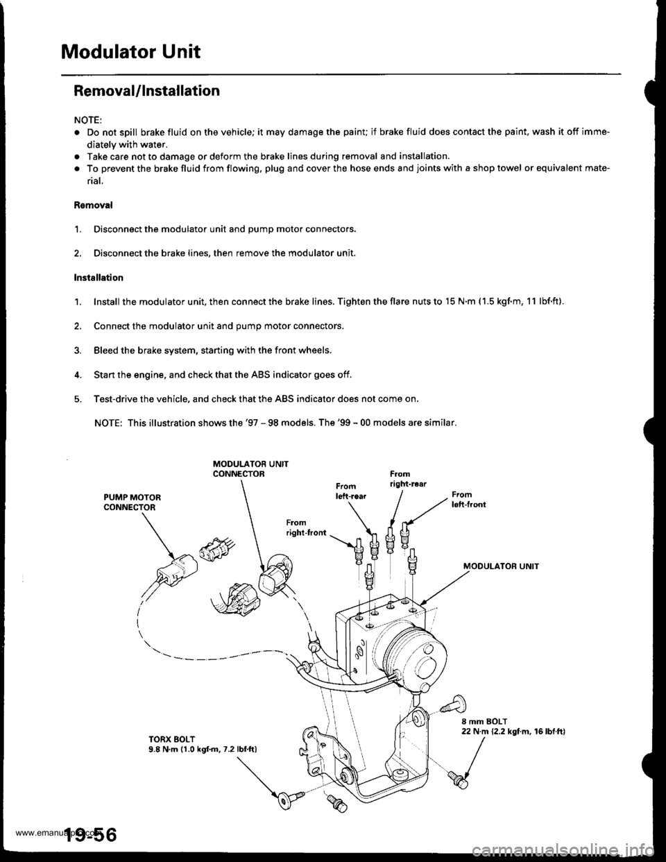
1. Disconnect the modulator unit and Dump motor connectors.
2. Disconnect the brake lines, then remove the modulator unit.
lnstallation
1. Install the modu lator u nit. then con nect the brake lines. Tighten the flare nuts to 15 N.m ( 1.5 kgf.m, 1 1 lbf.ft).
2. Connect the modulator unit and oumo motor connectors.
3. Bleed the brake system, staning with the front wheels.
4. Start the engine, and check that the ABS indicator goes off.
5. Test-drive the vehicle, and check that the ABS indicator does not come on,
NOTE: This illustration shows the '97 - 98 models. The'99 - 00 models are similar.
PUMP MOTORCONNECTOR
MODULATON UNIT\*\
,@
I
TORX EOLT9.8 N,m (1.0 kgf.m.7.2lbf ftl
19-56
www.emanualpro.com
Page 981 of 1395
Pulsers/Wheel Sensors
Wheel Sensor Replacement
NOTE;
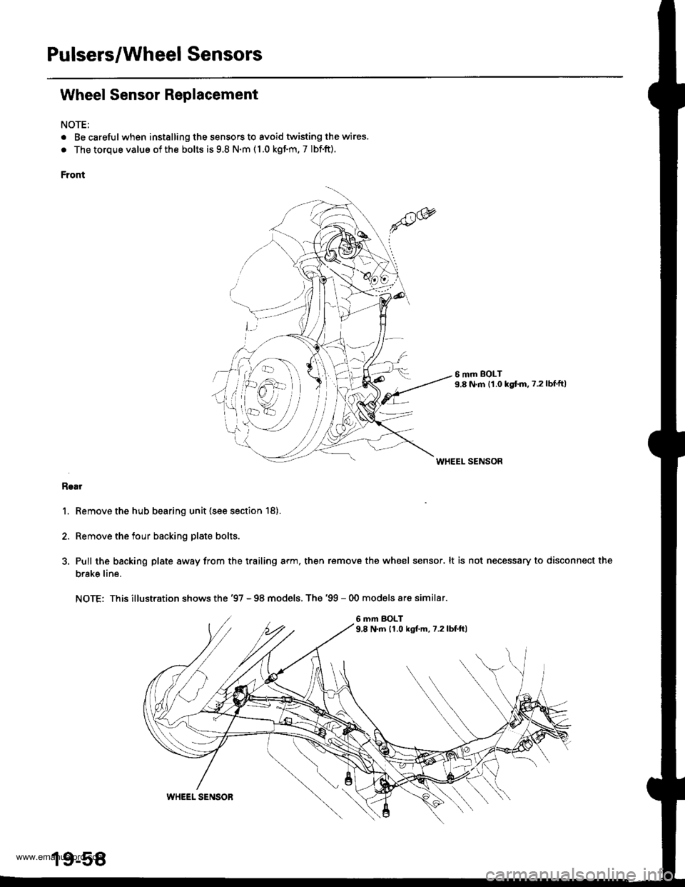
. Be carefulwhen installing the sensors to avoid twisting the wires.
. The torque value of the bolts is 9.8 N.m ( 1.0 kgf.m, 7 Ibf.ft).
Front
6 mm BOLT9.8 N.m {1.0 kgtm. ?.2lbf'ft)
WHEEL SENSOR
Rgar
1. Remove the hub bearing unit (see section 18).
2. Remove the tour backing plate bolts.
3, Pull the backing plate away from the trailing arm, then remove the wheel sensor. lt is not necessary to disconnect the
brake line.
NOTE: This illustration shows the '97 - 98 models, The '99 - 00 models are similar.
6 mm BOLT9,8 N.m 11.0 kgf.m, 7.2lbf.ft)
\all
19-58
WHEEL SENSOR
www.emanualpro.com
Page 991 of 1395
Doors
Front Door Glass and Regulator Replacement
CAUTION: Put on gloves to protect your hands,
1. Remove;
. Door panel (see page 20-7)
. Plastic cover (see page 20-21
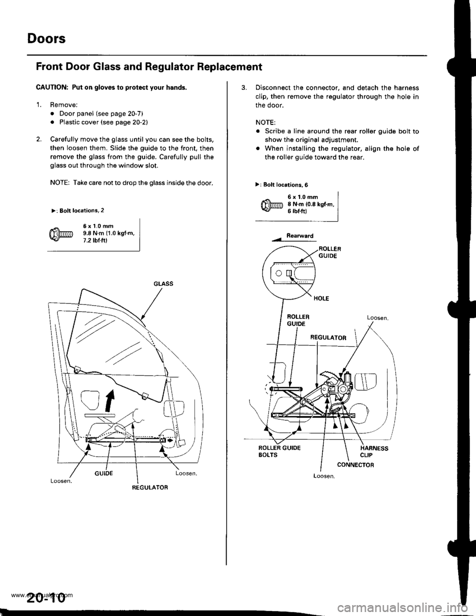
2. Carefully move the glass until you can see the bolts,
then loosen them. Slide the guide to the front, then
remove the glass from the guide. Carefully pull the
glass out through the window slot.
NOTE: Take care not to drop the glass inside the door.
>: Bolt locations,2
6xl.0mm9.8Nm(1.0kgt.m.7.2 tbt.ftl
GLASS
REGULATOR
20-10
3. Disconnect the connector, and detach the harness
clip, then remove the regulator through the hole in
the door.
NOTE:
. Scribe a line around the rear roller guide bolt to
show the original adjustment.
. When installing the regulator, align the hole of
the roller guide toward th€ rear.
>: Bolt locations,6
6x1.0mm8 N.m {0.8 kgt.m,6 rbtft)
Roaru/ard
Loosen,
www.emanualpro.com
Page 992 of 1395
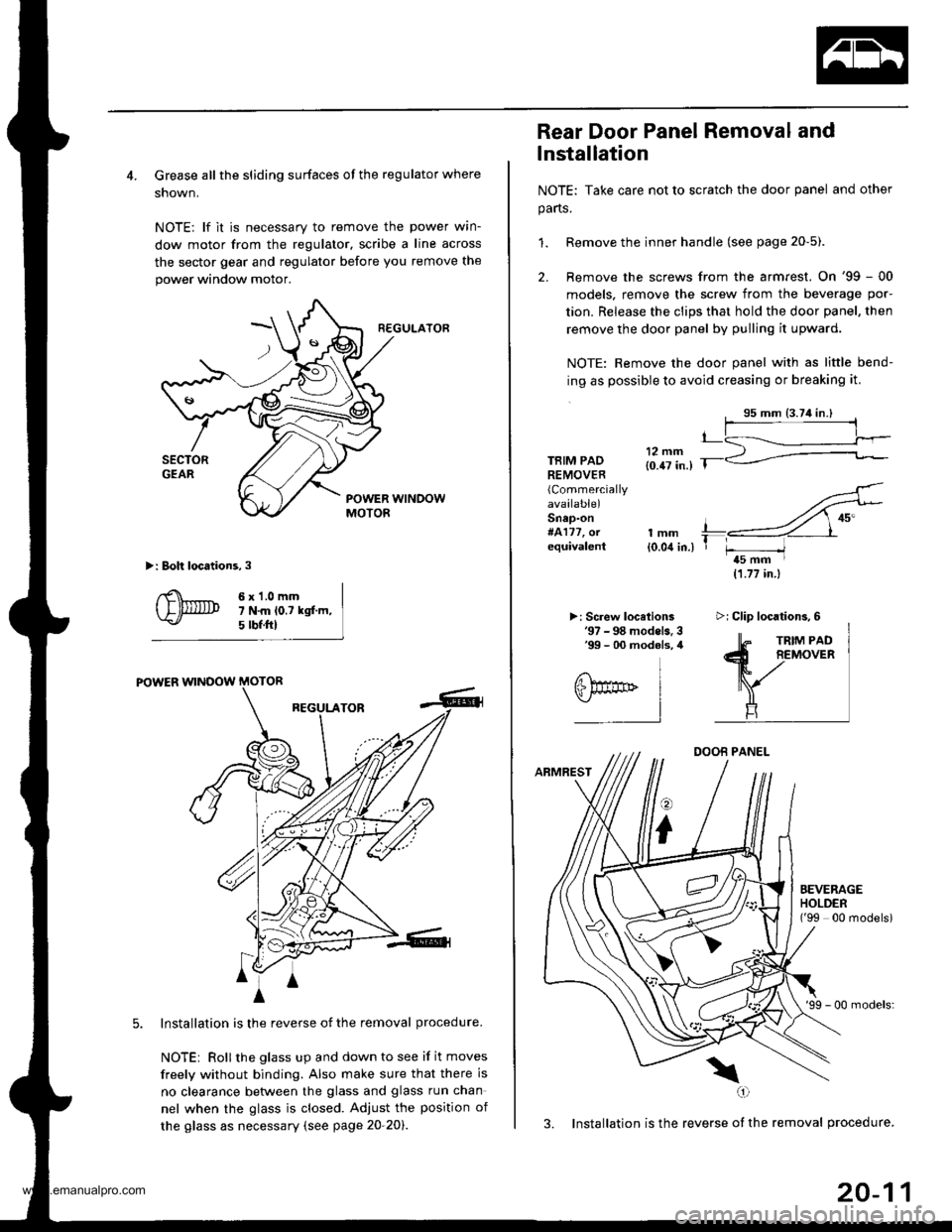
4. Grease all the sliding surfaces of the regulator where
shown.
NOTE: lf it is necessary to remove the power wrn-
dow motor from the regulator, scribe a line across
the sector gear and regulator before you remove the
power window motor.
R€GULATOF
>: Boh locations,3
6x1.0mm7 N.m lo.t kgf.m,5 tbf.ftl
POWER WINOOW MOTOR
REGULATOR
Installation is the reverse of the removal procedure.
NOTEi Rollthe glass up and down to see if it moves
freely without binding. Also make sure that there is
no clearance betlveen the glass and glass run chan
nel when the glass is closed. Adjust the position of
the glass as necessary (see page 20-20).
4
A
m^i
A
Rear Door Panel Removal and
lnstallation
NOTE: Take care not to scratch the door panel and other
parts.
1. Remove the inner handle (see page 20-5).
2. Remove the screws from the armrest. On '99 - 00
models, remove the screw from the beverage por-
tion. Release the clips that hold the door panel, then
remove the door panel by pulling it upward.
NOTE: Remove the door panel with as little bend-
ing as possible to avoid creasing or breaking it.
TBIM PADREMOVER(Commercially
available)Snap-on#4177, orequivalentlmm{0.04 in.)
>: Screw locelions'97 - 98 models. 3'99 - 00 modols, 4
11.77 in.)
DOOB PANEL
ARMREST
o
i
'99 - 00 models:
3. Installation is the reverse of the removal procedure.
\(,1
t_
T r-----/t5 mm I
EEVERAGEHOLDEN('99 00 modelsi
>i Clip locations,6
20-11
www.emanualpro.com
Page 996 of 1395
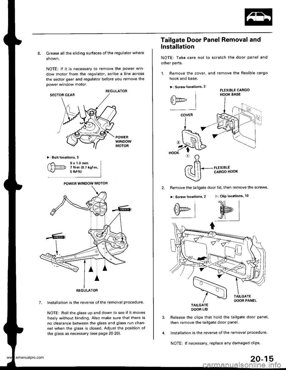
6. Grease all the sliding surfaces of the regulator where
shown.
NOTE: lf it is necessary to remove the power win-
dow motor from the regulator, scribe a line across
the sector gear and regulator before you remove the
power window motor.
REGULATORSECTOR GEAB
POWERwtNDowMOTOR
>: Bolt locations.3
6x1.0mm7 N.m 10.7 kgf.m,5 rbnftl
POWER WINDOW MOTOR
REGULATOR
7. lnstallation is the reverse of the removal procedure.
NOTEr Roll the glass up and down to see if it moves
freely without binding. Also make sure that there is
no clearance between the glass and glass run chan-
nel when the glass is closed. Adjust the position of
the glass as necessary {see page 20 20).
1. Remove the cover,
hook and base.
>: Screw locations.2
Tailgate Door Panel Removal and
lnstallation
NOTE: Take care not to scratch the door panel and
other parts.
and remove the flexible cargo
FLEXIBLE CARGOHOOK BASE
>: CliP locations.
?11 |
HPI,4| |
I
FLEXIBLECARGO HOOK
2. Remove the tailgate door lid, then remove the screws.
>: Screw locations.2
TAILGATEDOOR LIO
Release the clips that hold the tailgate door panel,
then remove the tailgate door panel.
Installation is the reverse of the removal procedure.
NOTE: lf necessary, replace any damaged clips.
3.
@t"
COVER
i
20-15
www.emanualpro.com
Page 1009 of 1395
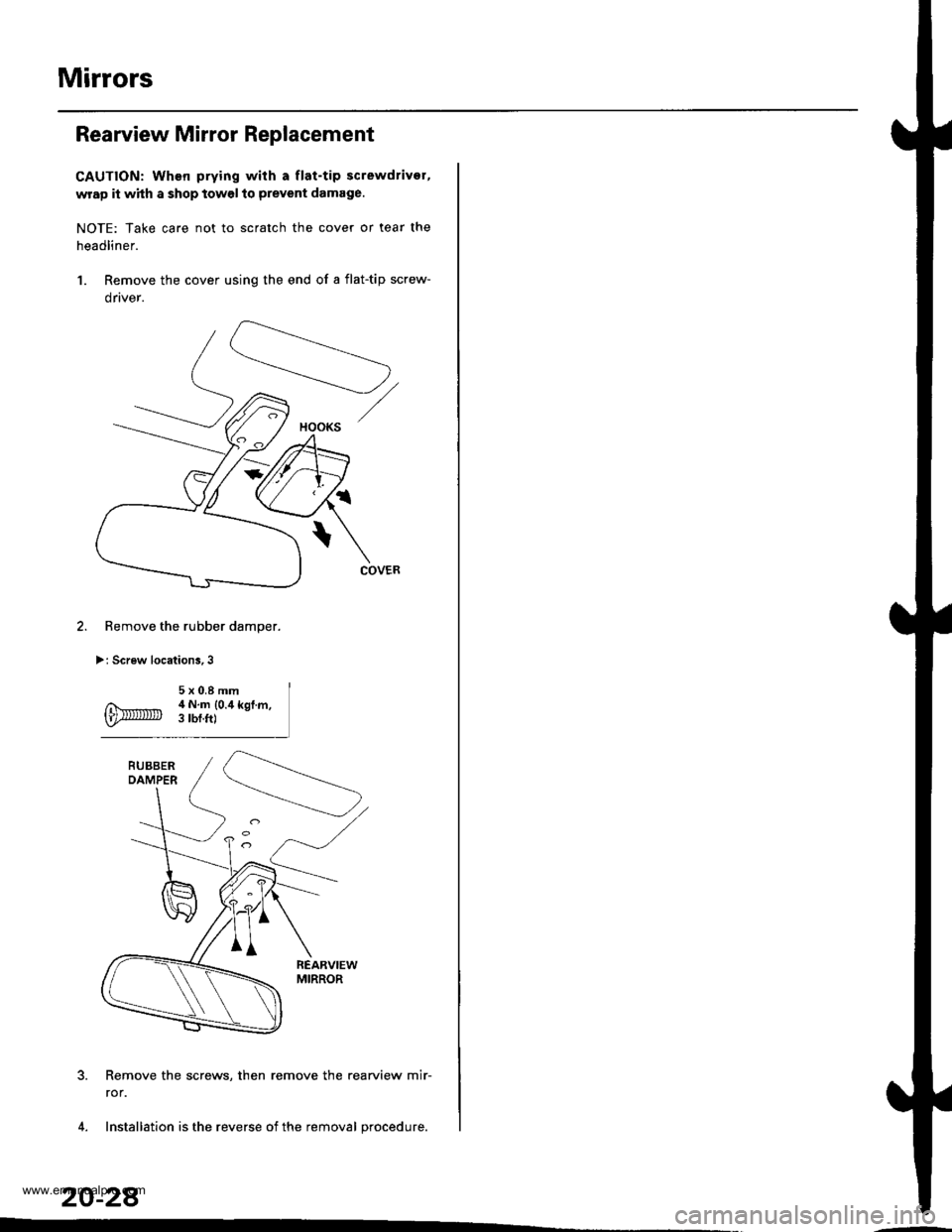
Mirrors
Rearview Mirror Replacement
CAUTION: When prying with a flat-tip screwdrivor,
wrap it whh a shop towel to prevent damage.
NOTE: Take care not to scratch the cover or tear the
headliner.
1. Remove the cover using the end of a flat-tip screw-
drtver.
Remove the rubber damper.
>: Screw locations,3
Remove the screws, then remove the rearview mir-
ror.
Installation is the reverse of the removal procedure.
20-28
HOOKS
www.emanualpro.com
Page 1011 of 1395
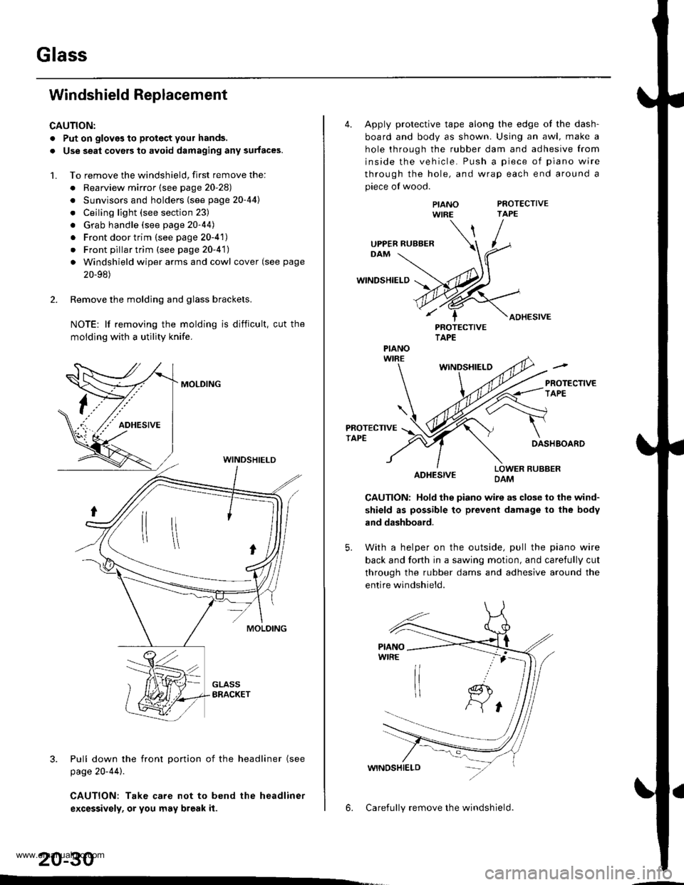
Glass
Windshield Replacement
CAUTION:
. Put on gloves to protect your hands.
. Use seat covers to avoid damaging any surfaces.
1. To remove the windshield, first remove the:
. Rearview mirror (see page 20-28)
. Sunvisors and holders (see page 20-44l'
. Ceiling light (see section 23)
. Grab handle (see page 20-44)
. Front door trim (see page 20-41)
. Front pillar trim (see page 20-41)
. Windshield wiper arms and cowl cover (see page
20-98)
2. Remove the molding and glass brackets.
NOTE: lf removing the molding is difficult, cut the
moldlng with a utility knife.
MOLDING
3. Pull down the front Dortion of the headliner (see
page 20-44).
CAUTION: Take care not to bend the headliner
excessivsly, or you may break it.
WINDSHIELD
20-30
4. Apply protective tape along the edge ot the dash-
board and body as shown. Using an awl, make a
hole through the rubber dam and adhesive from
inside the vehicle. Push a piece of piano wire
through the hole, and wrap each end around a
piece of wood.
PROTECTIVETAPE
WINDSHIELD
ADHESIVE
PIANOWIRE
PROTECTIVETAPE
WINDSHIELO
PROTECTIVETAPEDASHBOARD
ADHESIVELOWER RUBBERDAM
CAUTION: Hold the piano wire as close to the wind-
shield as possible to prevent damage to the body
and dashboard.
5. With a helper on the outside, pull the piano wire
back and fo(h in a sawing motion, and carefully cut
through the rubber dams and adhesive around the
entire windshield.
6. Carefully remove the windshield.
UPPER RUBBER
PIANO
www.emanualpro.com
Page 1021 of 1395
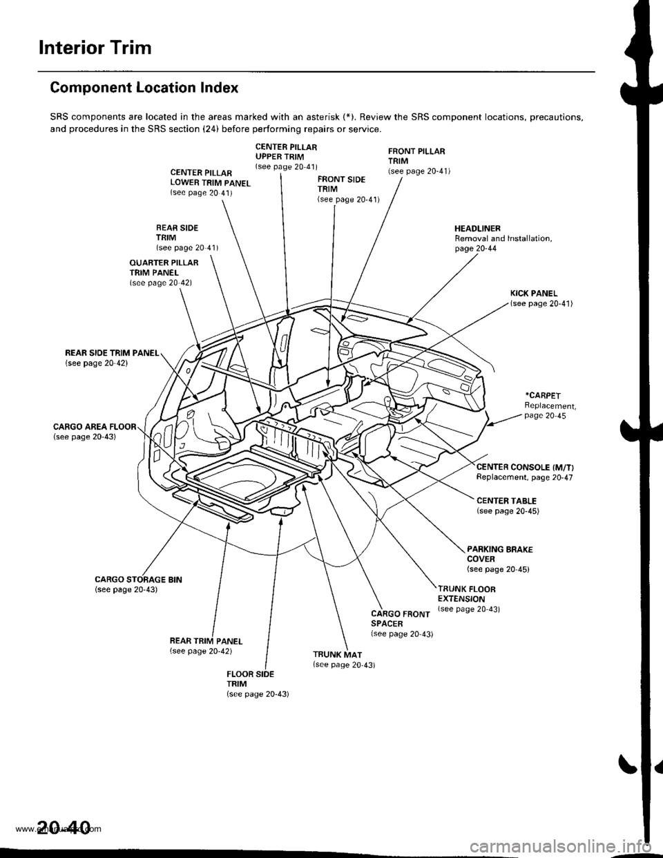
lnterior Trim
20-40
CARGO FRONTSPACER(see page 20 43)
FRONT PILLARTRIM(see page 20-41)
TRUNK FLOOREXTENSION(see page 20 43)
HEADLINERRemoval and lnstallation,page 20-44
Component Location Index
SRS components are located in the areas marked with an asterisk (*). Review the SRS component locations, precautions,
and procedures in the SRS section (24) before performing repairs or service.
CENTER PILLARUPPER TRIM(see page 20 41)CENTER PILLARLOWER TRIM PANEL(see page 20 41)
FRONT SIDETRIM(see page 20-41)
BEAR SIDETEIM(see page 20'41)
OUARTER PILLARTRIM PANEL(see page 20 42)
*CARPET
Replacement,page 20 45
CENTER CONSOLE IM/T}Replacement, page 20-47
CENTEN TABLE(see page 20-45)
PARKING BRAKECOVER(see page 20-45)
TRIM
www.emanualpro.com
Page 1025 of 1395
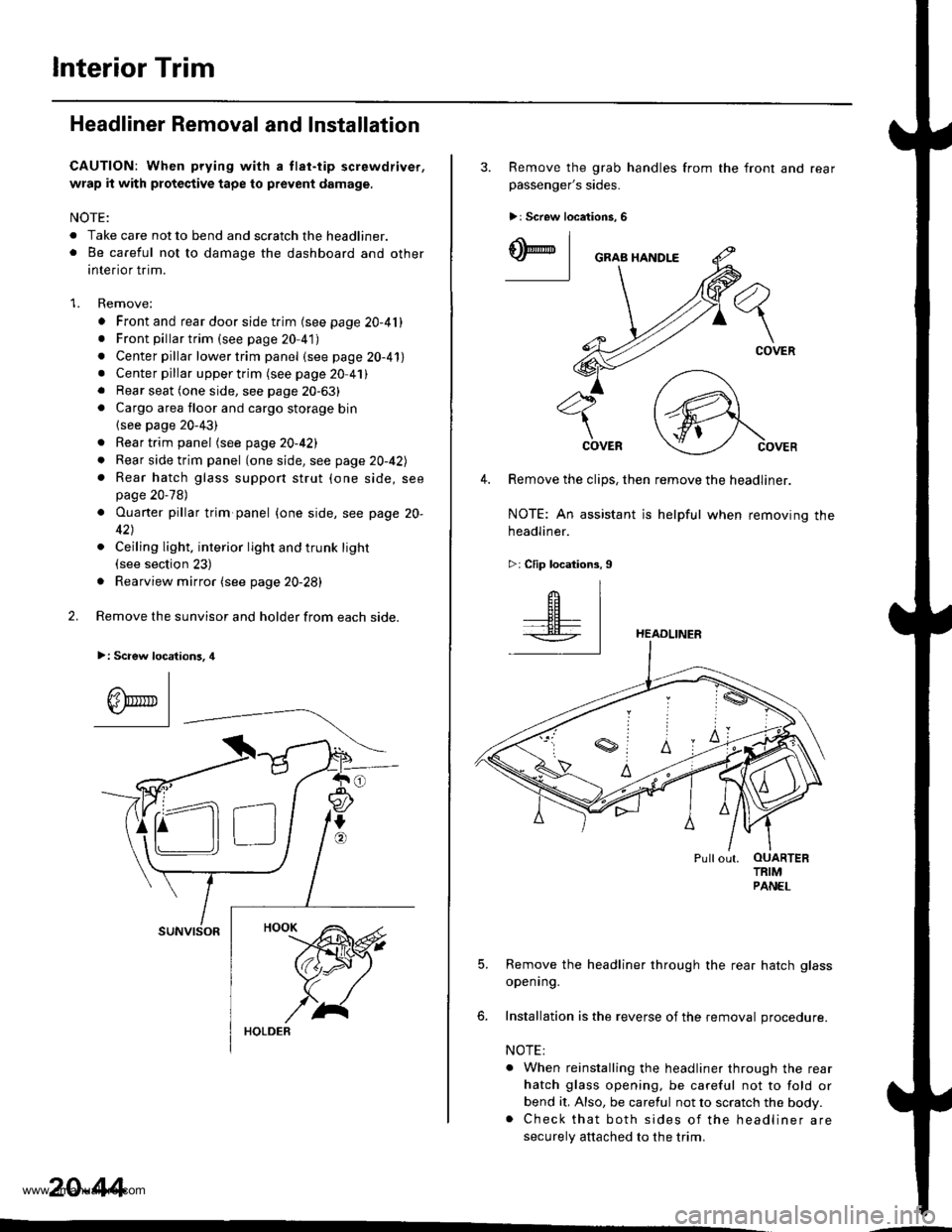
lnterior Trim
Headliner Removal and Installation
CAUTION: When prying with a tlat-tip screwdriver,
wrap it with protective tape to prevent damage.
NOTE:
. Take care not to bend and scratch the headliner.o Be careful not to damage the dashboard and other
interior trim.
1. Remove:
. Front and rear door side trim (see page 20-41). Front pillartrim (see page 20-41)
. Center pillar lower trim panel (see page 20-41). Center pillar upper trim (see page 20 41). Rear seat (one side, see page 20-63). Cargo area floor and cargo storage bin
{see page 20-43)
. Rear trim panel (see page 20-421
. Rear side trim panel (oneside, see page 20-42l,
. Rear hatch glass support strut (one side, seepage 20-78)
. Ouaner pillar trim panel {one side, see page 20-
42)
. Ceiling light, interior light and trunk light(see section 23)
. Rearview mirror (see page 20-28)
2. Remove the sunvisor and holder from each side.
>: Scaew location3, 4
I
A\"r- |Yr* || -
suNvtsoR
20-44
3. Remove the grab handles from
passenger's sides.
>r Screw locations, 6
the front and rear
ry_l
COVER
4. Remove the clips, then remove the headliner.
NOTE: An assistant is helpful when removing the
headliner.
>: Clip locations,9
HEADLINER
Pullout. OUARTERTRIMPANEL
5. Remove the headliner through the rear hatch glass
openrng.
6. Installation is the reverse of the removal procedure.
NOTE:
. When reinstalling the headliner through the rear
hatch glass opening, be careful not to fold or
bend it, Also, be careful not to scratch the body.. Check that both sides of the headliner are
securely attached to the trim.
www.emanualpro.com