Valve set HONDA CR-V 1999 RD1-RD3 / 1.G Owner's Manual
[x] Cancel search | Manufacturer: HONDA, Model Year: 1999, Model line: CR-V, Model: HONDA CR-V 1999 RD1-RD3 / 1.GPages: 1395, PDF Size: 35.62 MB
Page 590 of 1395
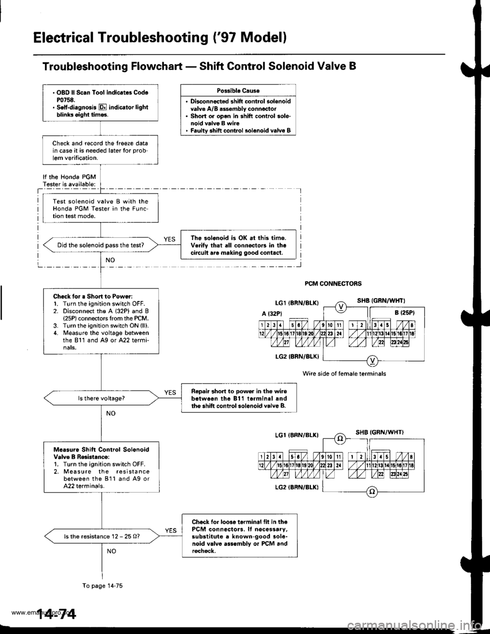
Electrical Troubleshooting ('97 Model)
Troubleshooting Flowchart - Shift Control Solenoid Valve B
Po33ibla Crusa
. Disconnec{ed shift cont.ol solenoidvalve A/B dssombly connector. Short or open in shift conlrol sole-noid valvg B wire' Faultv shift comrol 3olenoid valvo B
lf the Honda PGMT€ster is available:
PCM CONNECTORS
Wire side ot female terminals
. OBO ll Scan Toot indicrt8 CodoP0758.. Setf-diagnGis E indicator lightblinks oight tim93.
Check and r€cord the lreere datain case it is needed later for prob
lem verilication.
Test solenoid valve B with theHonda PGM Tester in the FLrnction test mode.
The 3olonoid is OK at this time.Verifv that all connoctors in thecircuit are making good contlct.Did the solenoid Dass the test?
Chock tor a Sho.t to Power:1. Turn the ignition switch OFF.2. Disconnect the A (32P) and B{25P) connectors Irom the PCM.3. Turn the ignition switch ON (ll).
4. Measuro the voltage botveenthe 811 and Ag or A22 termi-nats.
R.p.ir 3hort to power in the wirebotwo€n the 811 iormin.l andtho shift control sol.noid valve B.
M.6sure Shift Control SolonoidValve B Reaistanco:1. Turn the ignition switch OFF.2. Measure the r€sistancebetween the 811 and A9 orA22 terminals.
Checl lor loosc terminal fil in thePCM connactors. It nocessarv,substitute a known-good aole-noid vllvo asssmbly or PCM andr6chsck,
ls the resistance 12 - 25 O?
To page 14-75
14-74
www.emanualpro.com
Page 599 of 1395
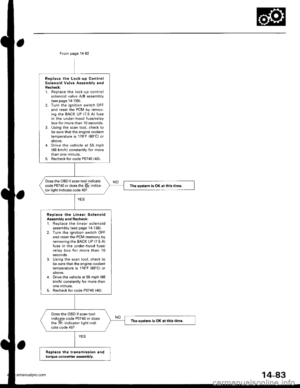
From page 14 82
Replace the Lock-up ControlSolenoid Valve Assembly andRecheck:1. Replace the lock-up controlsolenoid valve A/B assembly(see page 14-'135).2. Turn the ignition switch OFFand reset the PCM by remov-ing the BACK uP (7.5 A) fusein the under-hood fuse/relaybox for more than 10 seconds.3. lJsing the scan tool, check tobe sure that the engine coolanttemperature is 176"F 180'C) orabove,4. Drive the vehicle at 55 mph(88 km/h) constantly for moretnan one mrnute.5. Recheck for code P0740 (40).
Does the OBD ll scan tool indicatecode PO74O or doesthe El indicator light indicate code 40?The svstem is OK ai this time.
Replace the Linear Sol€noidA$embly and Recheck:'1. Beplace the linear solenoidassembly {see page 14-138).2. Turn the ignition switch OFFand reset the PCM memory byremoving the BACK UP (7.5 A)fuse in the underhood fuse/relay box for more than 10seconds.3. Using the scan tool, check tobe sure that the engine coolanttemperature is 176"F (80'C) orabove.4. Drive the vehicle at 55 mph (88
km/h) constantly for more thanone minute,5. Recheck for code P0740 {40).
Does the OBD ll scan toolindicate code P0740 or doesthe E indicator light indicate code 40?
The svsteo is OK at this tim€.
Replace the transmission andtorque convertor assembly.
www.emanualpro.com
Page 601 of 1395
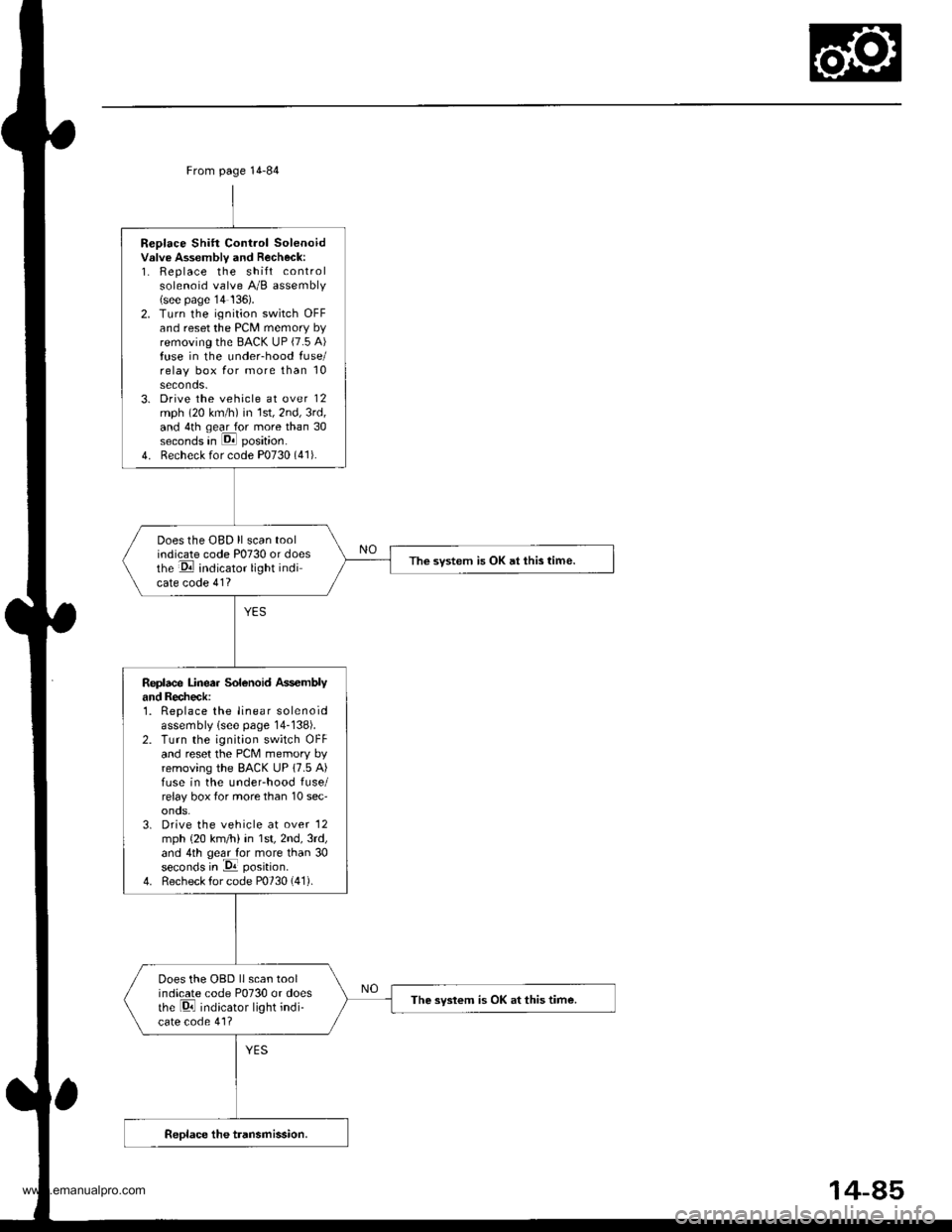
Replace Shift Control Solenoidvslve Assembly and Recheck:1. Replace the shift controlsolenoid valve A/B assembly(see page'14 136).2. Turn the ignition switch OFFand reset the PCM memory byremoving the BACK UP (7.5 A)fuse in the under-hood fuse/relay box for more than 10seconds.3. Drive the vehicle at over 12mph (20 km/h) in 1st,2nd,3rd,and 4th qear for more than 30seconds in E position.
4. Recheck for code P0730 (41).
Does the OBD ll scan toolindicate code P0730 or doesthe E indicator light indicate code 41?
The svstem is OK at this time.
Replace Linea. Solenoid Ass€mblyand Recheck:1. Replace the linear solenoidassembly lsee page 14-138).2. Turn the ignition switch OFFand reset the PcM memory byremoving the BACK UP 17.5 A)fuse in the underhood fuse/relay box tor more than 10 sec'onos.3. Drive the vehicle at over '12
mph {20 km/h) in 1st,2nd,3rd,and 4th geal for more than 30seconds in -Da position.
4. Recheck for code P0730 (41).
Does the OBD llscan toolindicate code P0730 or doesthe Di indicator light indi-cate code 41?
The syslem is OK at this time.
From page 14-84
14-85
www.emanualpro.com
Page 636 of 1395
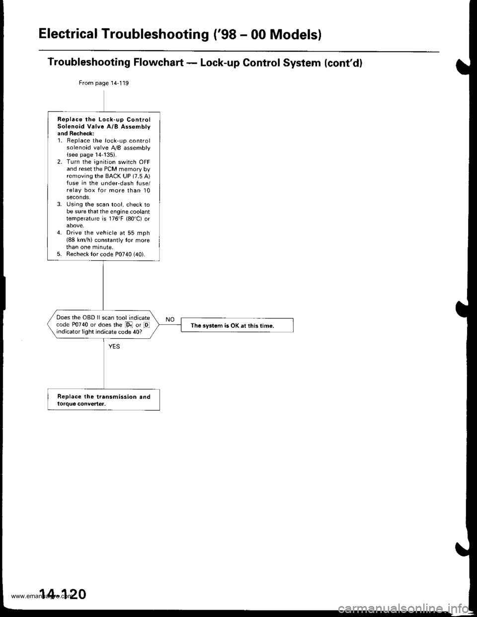
Electrical Troubleshooting ('98 - 00 Models)
Troubleshooting Flowchart - Lock-up Control System (cont'd)
From page 14-119
Replace the Lock-up ControlSolenoid Valve A/B Assomblyand Recheck:1. Replace the lock-up controlsolenoid valve A,/B assembly(see page 14-!35).2. Turn the ignition switch OFFand reset the PCM memory byremoving the BACK UP (7.5 A)fuse in the undeFdash fuse/relay box for more than 10seconds.3. Using the scan tool, check tobe sure that the engine coolanttemperature is 176"F {80'C) orabove.4. Drive the vehicle at 55 mph(88 km/h) constantly tor morethan one minute.5. Recheck {or code P0740 (40i.
Does the OBD ll scan tool indicatecode P0740 or does the [9i] or Eindicator light indicate code 40?The system is OK at this time.
14-120
www.emanualpro.com
Page 638 of 1395
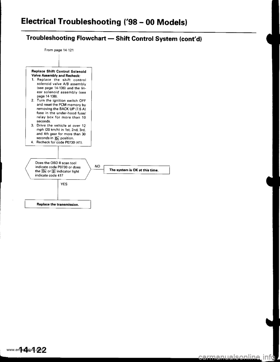
Electrical Troubleshooting {'gB - 00 Models}
Troubleshooting Flowchart - Shift Control System (cont,d)
From page 14 121
Replace Shilt Cont.ol SolenoidValve A$ambly and Recheck:'1. Replace the shift controlsolenoid valve A/B assembly(see page 14-136) and the lin,ear solenoid assembly (seepage 14138).2. Turn the ignition switch OFFand reset the PCM memory byremoving the BACK UP (7.5 A)tuse in the !nder-hood luse/relay box for more than 10seconos.3. Drive the vehicle at over '12
mph (20 km,/ti) in lst,2nd,3rd,and 4th gear tor more than 30seconds in E position.4. Recheck for code P0730 (41).
Does the OBD ll scan toolindicate code P0730 or doesthe E orE indicator lightindicate code 41?
Tho system is OK .l this tim€.
www.emanualpro.com
Page 672 of 1395

Symptom-to-Com ponent Chart
Hydraulic System (cont'd)
NOTES
See flushing procedure, page l4-264 and 265,
BSet idle rpm in gear to specified idle speed. lf still no good, adjust motor mounts as outlined in enginesection of this manual.
clf the large clutch piston O-ring is broken, inspect the piston groove for rough machining.
Dlf the clutch pack is seized or is excessively worn. inspect the other clutches fot wear, and check the orificecontrol valves, CPC valve, and linear solenoid for free movement.
lf the linear solenoid is stuck, inspect the clutches for wear.
lf the 1-2 shift valve is stuck closed. the transmission will not upshift. lf stuck open, the transmission hasno lst gear.
Hlf the 2nd orifice control valve is stuck, inspect the 2nd and 3rd clutch Dacks for wear.
lf the 3-4 orifice control valve is stuck, inspect the 3rd and 4th clutch packs for wear.
Jlf the clutch pressure control valve is stuck closed. the transmission will not shift out of lst gear.
Klmproper alignment of main valve body and torque converter housing may cause ATF pump seizure. Thesymptoms are mostly an rpm-related ticking noise or a high-pitched squeak.
Llf the ATF strainer is clogged with particles of steel or aluminum, inspect the ATF pump and differentialpinion shaft. lf both are OK and no cause for the contamination is found, replace the torque converter.
Mlf the lst clutch feed pipe guide in the end cover is scored by the mainshaft. inspect the ball bearing forexcessive movement in the transmission housing. lf oK, replace the end cover as it is dented. The o-rinounder the guide is probably worn.
N' Replace the mainshaft if the bushing for the 4th feed pipe is loose or damaged, lf the 4th feed pipe is darrFaged or out of round. replace the end cover.' Replace the mainshaft if the bushing for the l st feed pipe is loose or damaged. lf the 1st feed pipe is dam-aged or out of round, replace it.
oA worn or damaged sprag clutch is mostly a result of shifting the transmission in E!. E, or E positionwhile the wheels rotate in reverse. such as rocking the vehicle in snow.
PInspect the frame for collision damage.
lnspect for damage and wear:
l. Reverse selector gear teeth chamfers.
2. Engagement teeth chamfers of countershaft 4th and reverse gear.
3. Shift fork for scuff marks in center.
4. Differential pinion shaft for wear under pinion gears.
5. Bottom of 3rd clutch for swirl marks.
Replace items 1, 2, 3. and 4 if worn or damaged. lf transmission makes a clicking, grinding, or whirring noise,also replace mainshaft 4th gear, reverse idler gear, and countershaft 4th gear in addition to 1,2, 3, or 4.lf differential pinion shaft is worn, overhaul differential assembly, replace ATF strainer, and thoroughly cjeantransmission, flush torque converter. cooler, and lines,lf bottom of 3rd clutch is swirled and transmission makes gear noise. replace the countershaft and final drivenoear,
Be very careful not to damage the torque converter housing when replacing the main ball bearing. you
may also damage the ATF pump when you torque down the main valve body. This will result in ATF pumpseizure if not detected. Use the Drooer tools.
SInstall the main seal flush with the torque converter housing. lf you push it into the torque converterhousing until it bottoms out, it will block the fluid return passage and result in damage.
www.emanualpro.com
Page 693 of 1395
![HONDA CR-V 1999 RD1-RD3 / 1.G Owners Manual
r] REVERSE IDLER GEAR SHAFT/HOLDERA N€EDLE BEARING
..] TRANSMISSION HOUSING
al TRANSMISSION HOUSING OIL SEAL Replace.g SET BING.80 mm Selecrive part
O REVERSE GEAR COLLABE couNTERSHAFT REVERSE GEA HONDA CR-V 1999 RD1-RD3 / 1.G Owners Manual
r] REVERSE IDLER GEAR SHAFT/HOLDERA N€EDLE BEARING
..] TRANSMISSION HOUSING
al TRANSMISSION HOUSING OIL SEAL Replace.g SET BING.80 mm Selecrive part
O REVERSE GEAR COLLABE couNTERSHAFT REVERSE GEA](/img/13/5778/w960_5778-692.png)
r] REVERSE IDLER GEAR SHAFT/HOLDER'A N€EDLE BEARING
..] TRANSMISSION HOUSING
al TRANSMISSION HOUSING OIL SEAL Replace.g SET BING.80 mm Selecrive part
O REVERSE GEAR COLLABE couNTERSHAFT REVERSE GEAB
.9,] NEEDLE BEARINGi9 LOCK WASHER Replace..1!i REVERSE SHIFT FORKO REVERSE SELECToRiJ. REVERSE SELECTOR HUBii' COUNTERSHAFT 4TH GEAR.14 NEEDLE BEARINGiD D|STANCE coLLAR,28 mm Selective part(i3 COUNTERSHAFT 2NO GEABi7-] THRUST NEEDLE BEARING(10 COUNTERSHAFT 3RD GEAR(9 NEEDLE BEARINGE9 COUNTERSHAFI3RD GEAB COLLAR.li THRUST NEEDLE BEARING.?) SPLINEO WASHER,,O 3RD CLUTCH ASSEMBLY
€1 O-RING Beplace.i23 COUNTERSHAFT
4i SHIFT CONTROL SOLENOID COVER
?Z] HARNESS CLAMP BRACKET
?9] SHIFT CONTROL SOLENOID VALVE A/B ASSEMBLY
8 HARNESS CLAMP BRACKET
GI SHIFT CONTROL SOLENOID VALVE FILTER/GASKET
(4 MAINSHAFT 2ND GEARi49 NEEDLE BEARING
@ THRUST NEEDLE BEARING(49 MAINSHAFT
@r SEAL|NG R|NG,35 mm
O SEALING RING,29 mm
@ NEEDLE BEARING
.49 SET RING
€) lST.HOLD CLUTCH ASSEMBLY
O o-RING Replace.6E THRUST WASHER
€9 THRUST NEEDLE BEARING
6' NEEDLE EEARING
€ir SUB-SHAFT 4TH GEAR
6 THRUST NEEDLE BEARING
@ SUB.SHAFT 4TH GEAR COLLAR@ sUB-sHAFf
6I NEEDI-E B€ARING STOP
@ NEEDLE BEARING(6t ATF GUIDE CAP Replace.(64 TRANSMISSION HANGEB
@ BREATHER CAP
i@ MAINSHAFT SPEED SENSOR
6i O-RING Replace.
6D REVERSE IDLER GEAR
@r DOWEL PlN, 14 x 25 mm.6d SNAP RINGS
QlI SUB.SHAFT TRANSMISSION HOUSING BEARING
E) MAINSHAFT TRANSMISSION HOUSING BEABING.2, COUNTERSHAFI TRANSMISSION HOUSINGBEARING
@[E
t,n9t0@)@),lD
04
@
@@:���������������.ro)
ai
Replace-SNAP RINGTHRUST WASHEBTHRUST NEEDLE BEARINGMAINSHAFT 4TH GEARNEEDLE BEARINGSTHRUST NEEDLE BEARINGMAINSHAFT 4TH GEAB COLLAR2NO/4TH CLUTCH ASSEMBLYO-RING Replace.THRUST WASHER,36.5 x 55 mm Selective partTHRUST NEEOLE BEARING
DOWEL PlN, 14 x 25 mmCONNECTOR BRACKETATF MAGNETDOWEL PlN, 14 x 20 mmTRANSMISSION HOUSING GASKET Replace.DIFFERENTIAL ASSEMBLYDOWEL PlN, 10 x 12 mmO-RING Replace.TRANSFER ASSEMBLYTOROUE CONVERTER HOUSING OIL SEAL Replace.TOROUE CONVERTER HOUSING
TOROUE SPECIFICATIONS
Bolt/Nut No.Torque ValueSizeRgmarks
6A
6B
10A
12 N.m (1.2 kgf.m,8.7 lbf.ft)
14 N.m (1.4 kgf.m, 10 lbift)
44 N.m (4.5 kgf.m,33 lbf.ft)
6x 1.0 mm
6x 1.0 mm
10 x 1.25 mm
14-177
www.emanualpro.com
Page 699 of 1395
oatl,6
@!.,
ao6l
@o@@@@@o@@@)@@@@@@@@@@)
@@@@)@@@@@@@
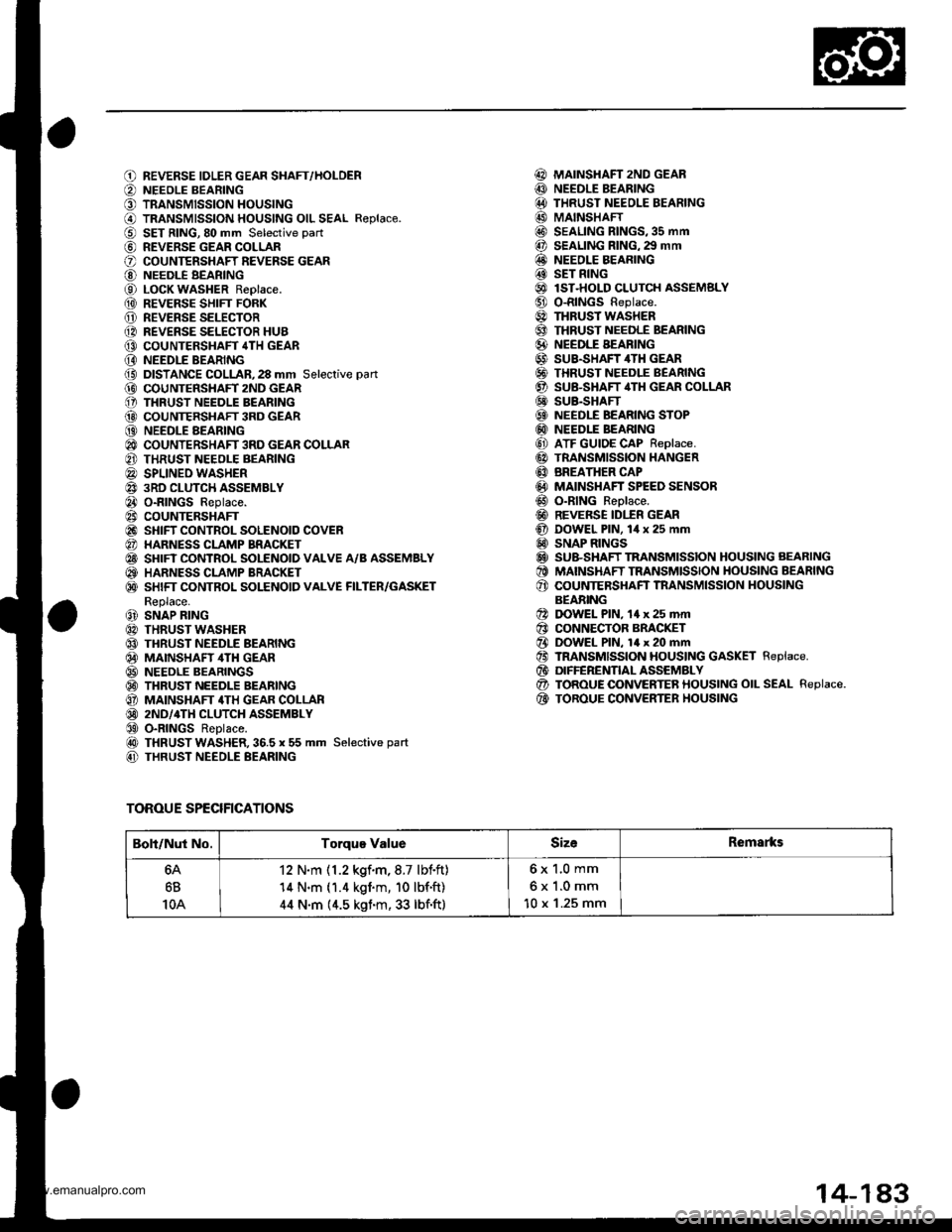
REVERSE IDLER GEAR SHAFT,/HOLDERNEEOLE BEARINGTRANSMISSION HOUSINGTRANSMISSION HOUSING OIL SEAL R€place.SET RING,80 mm Selective part
REVERSE GEAR COLLARCOUNTERSHAFT REVERSE GEARNEEDLE BEARINGLOCK WASHER Replace.REVERSE SHIFT FORKREVERSE SELECTORREVERSE SELECTOR HUBCOUNTERSHAFT 4TH GEARNEEDLE BEARINGDISTANCE COLLAR,28 mm Selective pan
COUNTERSIIAFT 2ND GEARTHRUST NEEDLE BEARINGCOUNTERSHAFT 3RD GEARNEEDLE AEARINGCOUNTERSHAFT 3RD GEAR COLLARTHRUST NEEOLE BEARINGSPLINEO WASHER3RD CLUTCH ASSEMBLYO-RINGS Replace.COUNTERSHAFTSHIFT CONTROL SOLENOID COVERHARNESS CLAMP BRACKETSHIFT CONTROL SOLENOID VALVE A/B ASSEMBLYHARNESS CLAMP BRACKETSHIFT CONTROL SOLENOID VALVE FILTER/GASKETReplace.SNAP RINGTHRUST WASHERTHRUST NEEDLE BEARINGMAINSHAF ,ITH GEARNEEDLE BEARINGSTHRUST NEEDLE BEARINGMAINSHAFT 4TH GEAR COLLAR2ND/4TH CLUTCH ASSEMBLYO-RINGS ReDlace.THRUST WASHER,36.5 x 55 mm Selective part
THRUST NEEDLE BEARING
MAINSHAFT 2ND GEARNEEDLE BEARINGTHRUST NEEOLE BEARINGMAINSHAFTSEALING RINGS,35 mmSEALING RING. 29 mmNEEDLE BEARINGSET RINGlST-HOLD CLUTCH ASSEMSLYO-RINGS Replace.THRUST WASHERTHRUST NEEDLE BEARINGNEEDLE BEARINGSUB.SHAFT 4TH GEARTHRUST NEEDLE BEARINGSU&SHAFT,ITH GEAR COLLARSUB.SHAFTNEEDLE BEARING STOPNEEDLE BEARINGATF GUIDE CAP Replace.TRANSMISSION HANGERBREATHER CAPMAINSHAFT SPEED SENSORO-RING Reolace.REVERSE IDI.fR GEARDOWEL PlN, lil x 25 mmSNAP RINGSSU&SHAFT TRANSMISSION HOUSING AEARINGMAINSHAFT TRANSMISSION HOUSING BEARINGCOUNTERSHAFT TNANSMISSION HOUSINGBEABINGDOWEL PlN, 14 x 25 mrnCONNECTOR BRACKETDOWEL PlN, 14 x 20 mmTRANSMISSION HOUSING GASKET Replace.DIFFERENTIAL ASSEMBLYTOROUE OONVERTER HOUSING OIL SEAL Replace.TOROUE CONVERTER HOUSING
@@@@@@@@@@@@@@@@@@@@@@@)@@@@@@@
@@@@@@@
TOROUE SPECIFICATIONS
Boli/Nut No.Torque ValueSizeRemarks
6B
10A
12 N.m (1.2 kgf.m,8.7 lbf.ft)'14 N.m (1.4 kgim, 10 lbf'ft)
44 N.m (4.5 kgim, 33 lbf.ft)
6x 1.0 mm
6x1.0mm
10 x '1.25 mm
14-1A3
www.emanualpro.com
Page 709 of 1395
Valve
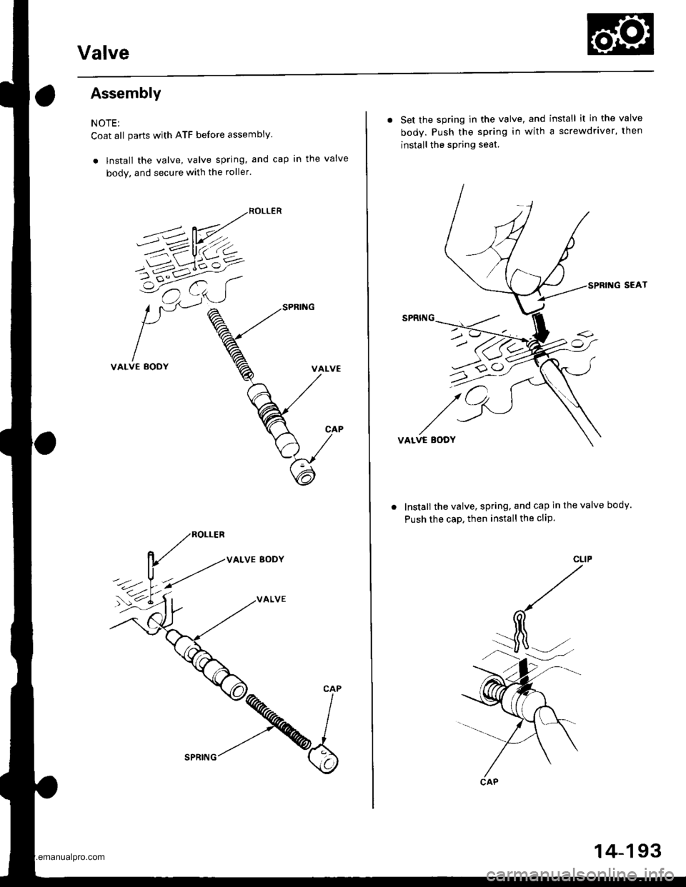
Assembly
NOTE;
Coat all parts with ATF before assembly.
. lnstall the valve, valve spring, and cap in the valve
body. and secure with the roller.
VALVE BODY
VALVE
. Set the spring in the valve, and install it in the valve
body. Push the spring in with a screwdriver, then
install the spring seat.
SEAT
VALVE EODY
Install the valve, spring, and cap in the valve body.
Push the caD, then install the cliP.
u>o
CAP
14-193
www.emanualpro.com
Page 779 of 1395

26. Connect the vehicle speed sensor (VSS). the coun-
tershaft speed sensor. and the A,/T gear position
switch connectors,
VEHICLE SPEEO
SPEED SENSOACO'{NECTOR
Connect the lock-up control solenoid valve connec-
tor, then install the harness clamp on the clamp
bracket.
HARNESS CI-AMP
27.
RADIATOR HOSECLAMP
TRANSMISSIONGROUND CAB1ITERMINAL
LOCK-UP OONTROLSOLENOID VALVECONNECTOR
6x1.0mm12 N'm (1.2 kgi.m,8.? tbtftl
28.
29.
Instail the transmission ground cable terminal on
the transmission hanger, and install the radiator
hose clamp on the transmission hanger,
Connect the starter cables to the starter, and install
the harness clamD on the clamD bracket. Make sure
the crimped side of the starter cable ring terminal is
facing out.
STARTEBCABLE
STARTER CAAtf,
Install the air cleaner housing assembly and the
intake air duct.
Refill the transmission with ATF (see page 14-161).
Connect the battery positive terminal and negative
terminal.
Set the parking brake, Start the engine, and shift the
transmission through all gears three times.
Check the shift cable adjustment (see page 14-271]-.
Check the tront wheel alignment and adjust it if
needed (see section 18).
Let the engine reach normal operating temperature
(the radiator fan comes on) with the transmission in
E or N position, then turn it off and check the ATF
level {see page 14-160).
Perform a road test (see page 14-157 and 14-158).
30.
31.
34.
CLAMP BRACKET
37.
14-263
www.emanualpro.com