Valve set HONDA CR-V 1999 RD1-RD3 / 1.G Service Manual
[x] Cancel search | Manufacturer: HONDA, Model Year: 1999, Model line: CR-V, Model: HONDA CR-V 1999 RD1-RD3 / 1.GPages: 1395, PDF Size: 35.62 MB
Page 895 of 1395

Power Steering Gearbox
Reassembly (cont'd)
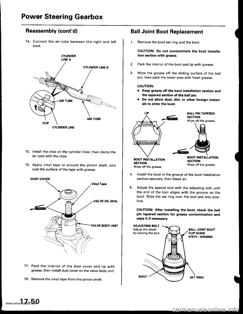
74. Connect the air tube between the right and left
boot,
CYLINDERLINE A
75. Install the clips on the cylinder lines, then clamp theair tube with the clips.
76. Apply vinyl tape to around the pinion shaft, andcoat the surface of the tape with grease.
DUST COVER
Vinyl Tsp€
VALVE OIL SEAL
VALVE BODY UNIT
Pack the interior of the dust cover and lio withgrease, then install dust cover on the valve bodv unit.
Remove the vinyl tape f.om the pinion shaft.
77.
CYLINDER LINE
17-50
SET RING
't.
Ball Joint Boot Replacement
Remove the boot set ring and the boot.
CAUTION: Do not contaminate the boot inslalla-
tion section with graase.
Pack the interior of the boot and lip with grease.
Wipe the grease off the sliding surface of the ballpin. then pack the lower area with fresh grease.
CAUTION:
. Keep grease off the boot installation section and
the tapered section of th€ ball pin.
. Do not allow dust, dirt, or other to.eign materi-
als to enter the boot.
EALL PIN TAPEREDSECTIONWipe olf the grease.
BOOT INSTALLATIONSECTIONWipe offthe grease.
B(X)T IT{STALLATIONsEclroNWipe off the grease.
ADJUSTING BOLTAdiust the depthby turning the bolt.
Install the boot in the groove of the boot installation
section securely. then bleed air.
Adjust the special tool with the adjusting bott untilthe end of the tool aligns with the groove on theboot. Slide the set ring over the tool and into posi-
I|on.
CAUTION: After installing the boot, chock the batlpin lapered section for grease contamination andwipe it it n€cessary.
www.emanualpro.com
Page 959 of 1395

Troubleshooting Precautions
ABS lndicalor
1 lf the system is oK, the ABS indicator goes off two seconds after turning the ignition switch oN 1l) wathout staningthe engine, and then comes on again and goes off after two seconds. This occurs because the ABS control unit isturned on by the lG2 power source.2. The ABS indicator comes on when the ABS control unit detects a problem in the system. However, even thouoh thesystem is operating properly, the ABs indicator will come on too, under the following conditions:. Signal disturbance
. Wheel spin
. Only drive wheels rotate. Battery voltage fluctuates
To determine the actual cause of the problem, question the customer about the problem, taking these conditions intoconsideration:
3 When a problem is detected and the ABS indicator comes on, the indicator can stay on until the ignition switch isturned OFF, or it can automatically go off, depending on the mode.. Indicator stays on untilthe ignition switch is turned off: When the system is in the system down mode.. Indicator automatically goes off: When the system is in the control inhibition mode.4 The ABS indicator stays on when the system is reactivated without erasing the DTC, but it goes off after starting thevehicle.
When the wheel sensor system is faulty and the ABS indicator comes on. the algorithm of the system automatically turnsoff the ABS indicator after the wheel speed signal returns to the normal speed. Also, when the DTc is erased, the cpu isreset and the ABS indicator goes off when the system checked out normal by the initial diagnosis.Therefore, test-drive the vehicle after servicing the wheel sensor system. and be sure that the ABS indicator does notcome on.
5 When the ABS control unit outputs battery voltage to the gauge assembly, the ABS indicator ooes off.
Diagnostic Trouble Code (DTCI
1. The diagnostic trouble code (DTc) is memorized when a problem is detected and the ABS indicator does not go off,or when the ABS indicator comes on.The DTc is not memorized when the ABS indicator comes on unress the cpu is activated,2 The memory can hold any number of DTCs. However, when the same DTc is detected twice or more, the tater one iswritten over the old one.
Therefore, when the same problem is detected repeatedly, it is recorded as one DTC.3. The DTCs are indicated in the order of ascending number, not in the order they occur.4. The DTCS are memorized in the EEPROM (non-volatile memorv).Therefore, the memorized DTcs cannot be canceled by disconnecting the battery. perform the specified procedures toerase the DTCS.
Self-diagnosis
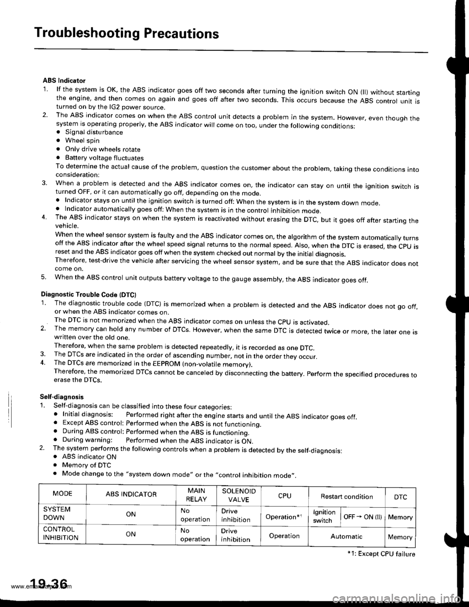
1. Self-diagnosis can be classified into these four categories:' Initial diagnosis: Performed right after the eng ine starts and untir theABS indicator goes off.. Except ABS control: Performed when the ABS is not functioning.. During ABS control: Performed when the ABS is functioning.. During warning: Performed when the ABS indicator is ON.2. The system performs the fo|owing contrors when a probrem is detected by the serf-diagnosis:. ABS indicator ON. Memorv of DTC. Mode changetothe "system down mode,, or the ,,control inhibition mode,,.
MODEABS INDICATORMAIN
RELAY
SOLENOID
VALVECPURestart conditionDTC
SYSTEM
DOWNONNo
operation
Drive
inhibitionOperation*rlgnition
switchoFF - ON l)Memory
CONTROL
INHIBITIONONNo
operal|on
Drive
inhibitionOperationAutomaticlMemory
*1: Except CPU failure
19-36
www.emanualpro.com
Page 1143 of 1395

Temperature Control
Adjustment
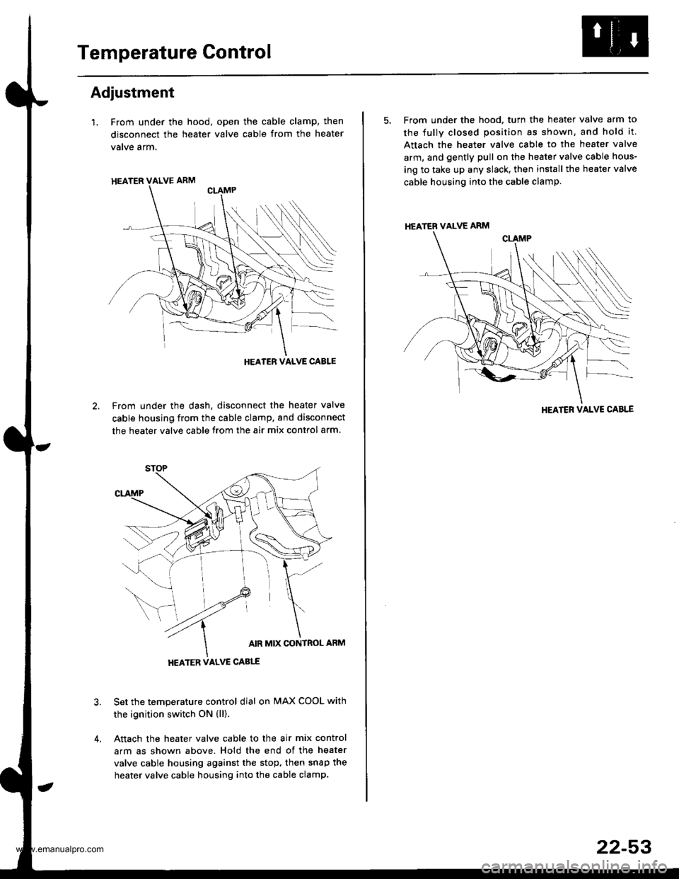
l. From under the hood, open the cable clamp, then
disconnect the heater valve cable from the heater
vatve arm.
From under the dash, disconnect the heater valve
cable housing from the cable clamp. and disconnect
the heater valve cable from the air mix contlol arm
Set the temperature control dial on MAX COOL with
the ignition switch ON (ll).
Attach the heater valve cable to the air mix control
arm as shown above. Hold the end of the heater
valve cable housing against the stop, then snap the
heater valve cable housing into the cable clamp.
HEATER VALVE ARM
HEATER VALVE CABLE
5. From under the hood. turn the heater valve arm to
the fullv closed position as shown, and hold it.
Attach the heater valve cable to the heater valve
arm, and gently pull on the heater valve cable hous-
ing to take up any slack, then install the heate. valve
cable housing into the cable clamp.
HEATER VALVE ARM
HEATER VALVE CABLE
22-53
www.emanualpro.com