Engine assembly HONDA CR-V 1999 RD1-RD3 / 1.G Service Manual
[x] Cancel search | Manufacturer: HONDA, Model Year: 1999, Model line: CR-V, Model: HONDA CR-V 1999 RD1-RD3 / 1.GPages: 1395, PDF Size: 35.62 MB
Page 853 of 1395
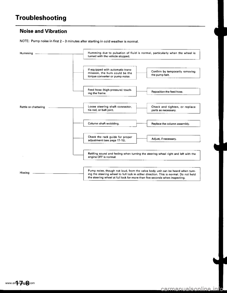
Troubleshooting
Noise and Vibration
NOTE: Pump noise in first 2 - 3 minutes after starting in cold weather is normal.
Humming
Rattle or chattering
Humming due to pulsation of fluid is normal, particularly when the wheel isturned with the vehicle stooDed.
lf equipped with automatic trans-mission, the hum could be thetorque converter or pump noase.
Confirm by temporarily removingthe pump belt.
Feed hose (high-pressure) touch-ing the frame.Beposition the feed hose.
Loose steering shaft connector,tie-rod, or balljoint.Check and tighten, or replaceparts as necessary,
Column shaft wobbling.Roplace the column assembly.
Check the rack guide for properadjustment (see page 17-15).Adjust, if necessary.
Rattling sound and feeling when turning the steering wheel right and left with th€engine OFF is normal.
Pump noise, though not loud, from the valve body unit can be heard when turn-ing the steering wheel to full lock in either direction. This is normal. Do not holdthe steering wheel at full lock lor more than five seconds when inspecting.
17-8
www.emanualpro.com
Page 865 of 1395
Steering Column
Removal/lnstallation
SRS components are located in this area. Review the
SRS component locations, precautions, and procedures
in the SRS section (24) before performing repairs or ser-
vice.
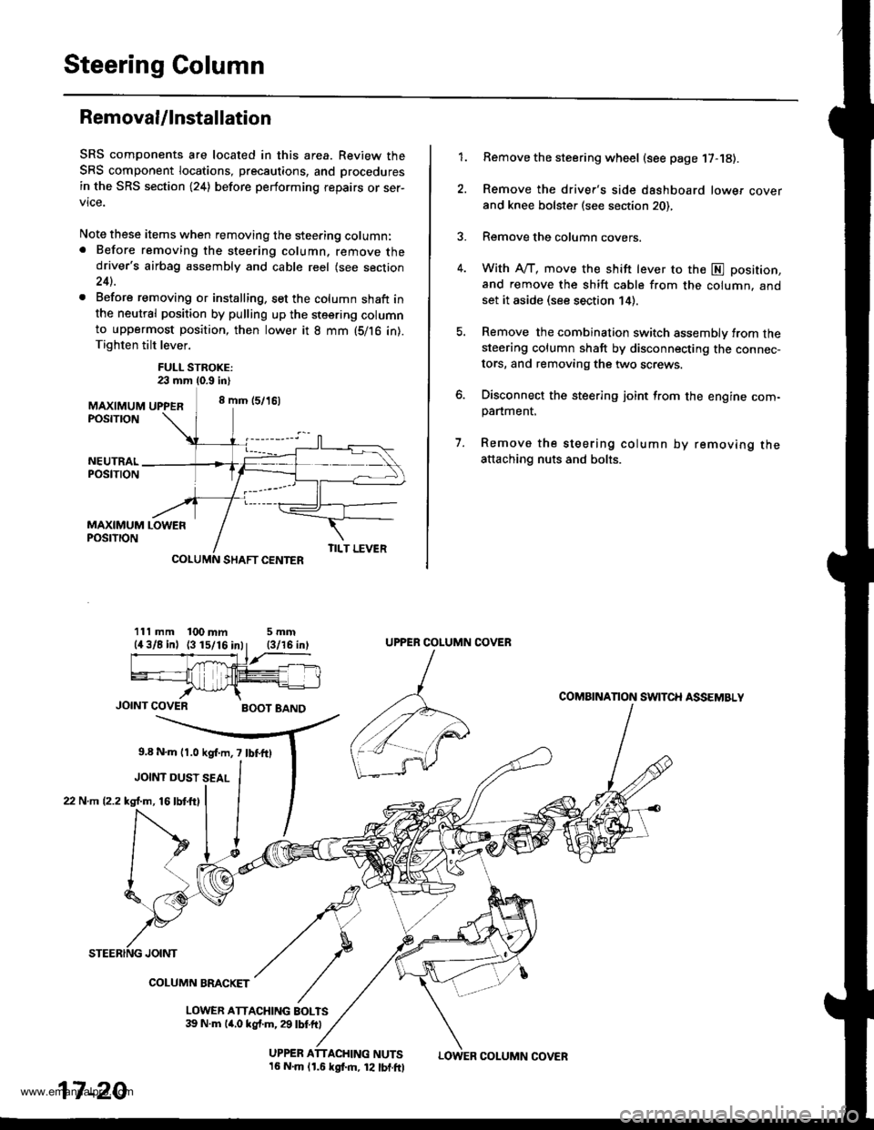
Note these items when removing the steering column:. Before removing the steering column, remove thedriver's airbag assembly and cable reel (see section24).
. Before removing or installing, set the column shaft inthe neutral position by pulling up the steering columnto uppermost position, then lower it 8 mm (5/16 in).Tighten tilt lever.
FULL STROKE:23 mm 10.9 in)
MAXIMUM UPPER8 mm (5/16)
POSTTTON
Remove the steering wheel (see page 17-18).
Remove the driver's side dashboard lower cover
and knee bolster (see section 20),
Remove the column covers.
With A"/T, move the shift lever to the E position,
and remove the shift cable from the column. andset it aside (see section 14).
Remove the combination switch assembly from thesteering column shaft by disconnecting the connec-
tors, and removing the two screws.
Disconnect the steering joint from the engine com-panment.
Remove the steering column by removing theattaching nuts and bolts.
7.
1.
MAXIMUM LOWERPOSTTTON
SHAFT CENTER
111 mm 100 mm5mm
JOINT COVERBOOT BAND
9,8 N.m l r .0 kgf.m, 7 lbf.fO
JOINT DUST SEAL
22 N.m (2.2 kgl.m, 16lbtftl
TILT LEVER
UPPER ATTACHING NUTS16 N.m lr.6 kgf.m, 12 lbf.ftl
UPPER COLUMN COVER
COMAINANON SWITCH ASSEMBLY
JOINT
COLUMN BMCKET
LOWER ATTACHING BOLTS39 N.m lir,o kgf.m, 29 lbf.ft)
17-20
LOWER COLUMN COVER
www.emanualpro.com
Page 876 of 1395
Power Steering Gearbox
Removal
Note these items during removal:
. Using solvent and a brush, wash any oil and dirt off
the valve body unit its lines, and the end if the gear-
box. Blow dry with compressed air.
. Be sure to remove the steering wheel before discon-
necting the steering joint. Damage to the cable reel
can occur.
. With 4WD. tilt the engine with a jack to expand the
clearance between the transfer assembly and rear
beam when removing the steering gearbox from the
rear oeam.
Do not remove the steering gearbox by removing the
transfer assembly from the transmission.
1. Drain the power steering fluid as described on page'17-15.
Raise the vehicle, and suppon it on safety stands in
the proper locations (see section 1).
Remove the front wheels,
Remove the drive/s airbag assembly {see section 24).
Remove the steering wheel {see page 17-18).
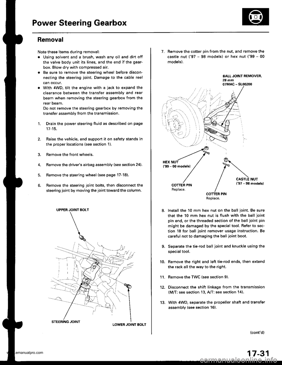
Remove the steering joint bolts, then disconnect the
steering joint by moving the joint toward the column.
UPPER JOINT BOLT
LOWER JOINT BOLT
13.
7. Remove the cotter pin from the nut, and remove the
castle nut {'97 - 98 models) or hex nut ('99 - 00
models).
COTTER PINReplace.
Install the 10 mm hex nut on the ball joint. Be sure
that the 10 mm hex nut is flush with the ball joint
pin end, or the threaded section of the ball joint pin
might be damaged by the special tool. Refer to sec-
tion 18 for ball joint remover usage instruction, Be
careful not to damaging the ball joint boot.
Separate the tie-rod ball joint and knuckle using the
special tool.
Remove the right and left tie-rod ends, then extend
the rack all the way to the right.
Remove the TWC (see section 9).
Disconnect the shift linkage from the transmission
(M/T: see section 13, A/T: see section 14).
With 4WD. separate the propeller shaft and transfer
assembly (see section 161.
10.
11.
(cont'd)
17-31
www.emanualpro.com
Page 878 of 1395
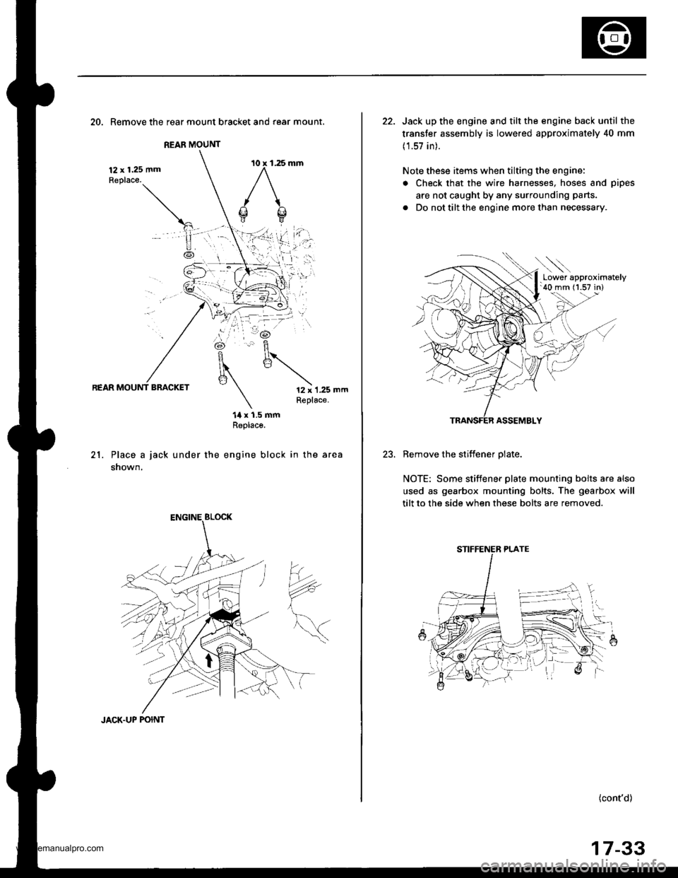
REAR MOUNT
20. Remove the rear mount bracket and rear mount.
12 x 1.25 mmReplace.
REAR MOUNT BRACKET12 x 1.25 mmReplace.
21.
14 x 1.5 mmReplaco.
Place a jack under the engine block in the area
shown,
?*
JACK.UP POINT
17-33
22. Jack up the engine and tilt the engine back until the
transfer assembly is lowered approximately 40 mm
(1.57 in).
Note these items when tilting the engine:
. Check that the wire harnesses, hoses and pipes
are not caught by any surrounding parts.
. Do not tilt the engine more than necessary.
ASSEMBLY
Remove the stiffener olate.
NOTE: Some stiffener plate mounting bolts a.e also
used as gearbox mounting bolts. The gearbox will
tilt to the side when these bolts are removed.
(cont'd)
.Lower approximately'40 mm (1.57 in)
STIFFENER PLATE
www.emanualpro.com
Page 898 of 1395
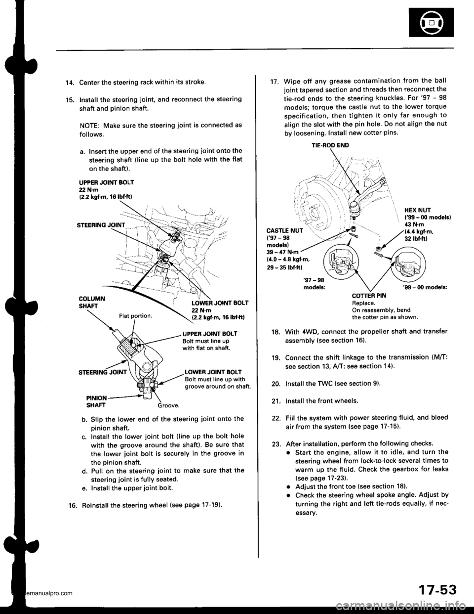
't 4.
15.
Center the steering rack within its stroke.
Install the steering joint, and reconnect the steering
shaft and pinion shaft.
NOTE: Make sure the steering joint is connected as
follows.
a. Insen the upper end of the steering joint onto the
steering shaft (line up the bolt hole with the flat
on the shaft).
UPPER JOINT BOLT22 N.m12.2 kgf.m, 16lbl.ft,
STEERING JOINT
COLUMNSHAFTLOWER JOINT BOLT22 N.m12.2 kgf.m, 16lbtftl
UPPER JOINT BOLTBolt must line upwith tlat on shatt.
LOWER JOINT BOLTBolt must line up withgroove around on shaft.
PINIONSHAFT
b, Slip the lower end of the steering ioint onto the
pinion shaft.
c. Install the lower joint bolt (line up the bolt hole
with ths groove around the shaft). Be sure that
the lower joint bolt is securely in the groove in
the pinion shaft.
d. Pull on the steering joint to make sure that the
steering joint is fully seated.
e, Install the upper joint bolt,
Reinstall the steering wheel {see page'17-19).16.
17-53
17. Wipe off any grease contamination trom the ball
joint tapered section and threads then reconnect the
tie-rod ends to the steering knuckles. For'97 - 98
models; torque the castle nut to the lower torque
specification, then tighten it only far enough to
align the slot with the pin hole. Do not align the nut
by loosening. Install new cotter pins.
CAST1T NUT(9t - 98modol!)
HEX NUTl'g!t - 00 modeb)il:l N.m14.4 ksl.m,32 tbf.f0
39 - iU N'm
lil.o - 4.8 kgl.m,
29 - 35 tbf.ftl
18.
19.
20.
21.
22.
23.
'99 - lD modeb:
COTTER PINRePlace.on reassembly, bendthe cotter Pin as shown.
With 4WD, connect the propeller shaft and transfer
assembly (see section 16).
Connect the shift linkage to the transmission (M/T:
see section 13, A,/T; see section 14).
Installthe Twc (see section 91.
lnstall the front wheels,
Fill the system with power steering fluid, and bleed
air from the system (see page 17-15).
After installation. perform the following checks.
. Start the engine, allow it to idle, and turn the
steering wheel from lock-to-lock several times to
warm up the fluid. Check the gearbox for leaks
(see page 17-23).
. Adjust the front toe (s€e section 18).
. Check the steering wheel spoke angl€. Adjust by
turning the right and left tie-rods equally, if nec-
essary.
TIE.ROO END
www.emanualpro.com
Page 912 of 1395
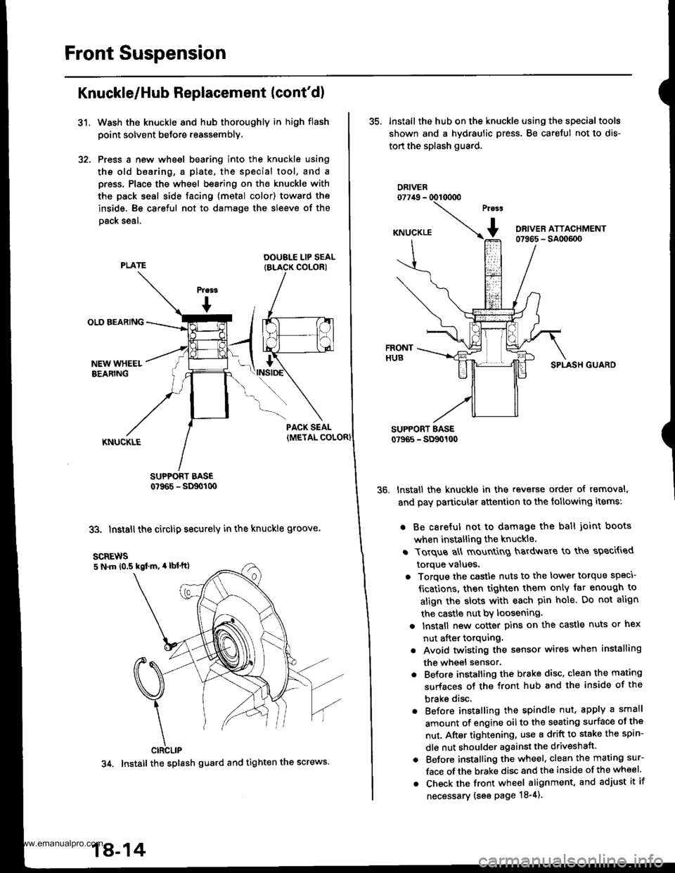
Front Suspension
31.
Knuckle/Hub Replacement (cont'dl
Wash the knuckle and hub thoroughly in high flash
point solvent before reassembly,
Press a new wheel bearing into the knuckle using
the old b6aring, a plate. the special tool, and a
press. Place the wheel bearing on the knuckle with
the pack seal side facing (metal color) toward the
inside. Be careful not to damage the sleeve of the
Dack seal.
DOUBLE LIP SEALIBLACK COLORI
SUPPORT BASE0?965 - SD90t00
33. Install the circlip securely in the knuckle groove.
35. lnstall the hub on the knuckle using the specialtools
shown and a hydraulic press. Be careful not to dis-
tort the splash guard.
ORIVER077irg - 0010000
SPLASH GUARO
lnstall the knuckle in the reverse order of removal,
and pay particular attention to the following items:
. Be careful not to damage the ball joint boots
when installing the knuckle.
r Torque a\ mount
g hardv{are to ths speci{ied
torque values,
o Torque the castle nuts to the lower torque speci
fications, then tighten them only iat enough to
align the slots with each pin hole. Do not align
the castle nut by loosening.
a lnstall new cotter pins on the castle nuts or hex
nut after torquing.
. Avoid twisting the sensor wires when installing
the wheel sensor.
. Before installing the brake disc, clean the mating
surfaces of the front hub and the inside of the
brake disc.
. Before installing the spindle nut, apply a small
amount of engine oil to the seating surface oJ the
nut. After tightening, use a drift to stake the spin-
dle nut shoulder against the driveshaft.
. Before installing the wheel. clean the mating sur-
face of the brake disc and the inside of the wheel.
. Check the front wheel alignment, and adjust it if
necessary {see page 18-4).
scREws5 N.m 10.5 kgl m, 4 lbl'tt)
CIRCLIP
34. Install the splash guard and tight€n the screws.
18-14
www.emanualpro.com
Page 920 of 1395
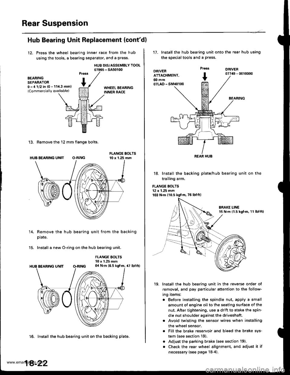
Rear Suspension
Hub Bearing Unit Replacement (cont'd)
12, Press the wheel bearing inner race from the hub
using the tools, a bearing separator, and a press.
HUB DIS/ASSEMBLY TOOL07965 - SA50100
BEARINGSEPARATOR0 -,t 1/2 in {0 - 11i1.3 mml(Commercially qvailable)
13. Remove the 12 mm flange bolts.
HUB BEARING UN]T O.RING
14. Remove the hub bearing unit from the backing
plate.
15. Install a new O-ring on the hub bearing unit.
FLANGE BOLTS10 x 1.25 mm64 N.m (6.5 kgf.m, 47 lbf.ftl
16. Install the hub bearing unit on the backing plate.
18-22
't7.Install the hub bearing unit onto the rear hub using
the special tools and a press.
DRIVERATTACHMENT,60 mm07LAO - SM40100
Prcss
+
DRIVER07749 - 0010000
BEARING
18. Install the backing plate/hub
trailing arm.
FLANGE BOLTS12 x 1.25 mm103 N.m 110.5 kgf'm,75lbfft)
bearing unit on the
19. Install the hub bearing unit in the reverse order of
removal, and pay particular attention to the follow-
ing items:
. Before installing the spindle nut, apply a small
amount of engine oil to the seating surface of the
nut, After tightening, use a drift to stake the spin-
dle nut shoulder against the driveshaft.
. Avoid twisting the sensor wires when installing
the wheel sensor,
. Fill the brake reservoir and bleed the brake sys-
tem {see section 19).
. Adjust the parking brake (see section 191.
. Check the rear wheel alignment, and adjust it if
necessary (see page 18-4).
REAR HUB
www.emanualpro.com
Page 938 of 1395
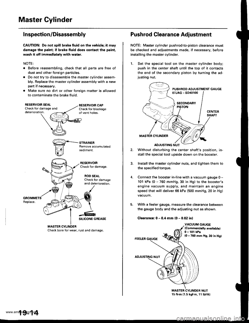
Master Cylinder
I nspection/Disassembly
CAUTION: Do not spill brake fluid onthe vehicle; it may
damsge the paint; il brake fluid does contact th6 paint.
wash it off immodiately with water.
NOTE:
. Before reassembling, check that all parts are free of
dust and other foreign particles.
. Do not try to disassemble the master cylinder assem-
bly. Replace the master cylinder assembly with a new
pan it necessary,
. Make sure no dirt or other foreign matter is allowed
to contaminate the brake fluid.
RESERVOIR SEALCheck for damaoe anddeterioration,
RESERVOIRCheck for damage.
ROD SEALCheck for damageand deterioration.
-€-1SILICONE GREASE
MASTER CYLINOERCheck bore for wear, rust and damage.
19-14
Pushrod Clearance Adjustment
NOTE: Master cylinder pushrod-to-piston clearance must
be checked and adjustments made, if necessary. before
installing the master cylinder.
1. Set the special tool on the master cylinder body;
push in the center shaft until the top ot it contacts
the end of the secondary piston by turning the ad-justing nut.
PUSHROD ADJUSTMENT GAUGE07JAG - SD{o100
SECONDARY
MASTER CYLINDER
ADJUSTING NUT
Without disturbing the center shaft's position, in-
stallthe special tool upside down on the booster.
Install the master cylinder nuts, and tighten them to
the sDecified toroue.
Connect the booster iniine with a vacuum gauge 0 -
101 kPa (0 - 760 mmHg, 30 in Hg) to the booster's
engine vacuum supply, and maintain an engine
speed that will deliver 66 kPa (500 mmH9, 20 in Hg)
vacuum.
With a feeler gauge, measure the clearance between
the gauge body and the adiusting nut as shown.
Clearanco: 0 - 0.4 mm (0 - 0.02 inl
VACUUM GAUGElCommo.cidly 6vailablcl0 - 101 kPtl0 - 760 mm Hg, 30 in Hgl
MASTER CYLINDER NUT15 N.m 11.5 kgt m, 11 lbt.ftl
www.emanualpro.com
Page 959 of 1395
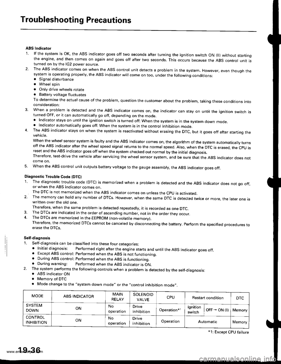
Troubleshooting Precautions
ABS lndicalor
1 lf the system is oK, the ABS indicator goes off two seconds after turning the ignition switch oN 1l) wathout staningthe engine, and then comes on again and goes off after two seconds. This occurs because the ABS control unit isturned on by the lG2 power source.2. The ABS indicator comes on when the ABS control unit detects a problem in the system. However, even thouoh thesystem is operating properly, the ABs indicator will come on too, under the following conditions:. Signal disturbance
. Wheel spin
. Only drive wheels rotate. Battery voltage fluctuates
To determine the actual cause of the problem, question the customer about the problem, taking these conditions intoconsideration:
3 When a problem is detected and the ABS indicator comes on, the indicator can stay on until the ignition switch isturned OFF, or it can automatically go off, depending on the mode.. Indicator stays on untilthe ignition switch is turned off: When the system is in the system down mode.. Indicator automatically goes off: When the system is in the control inhibition mode.4 The ABS indicator stays on when the system is reactivated without erasing the DTC, but it goes off after starting thevehicle.
When the wheel sensor system is faulty and the ABS indicator comes on. the algorithm of the system automatically turnsoff the ABS indicator after the wheel speed signal returns to the normal speed. Also, when the DTc is erased, the cpu isreset and the ABS indicator goes off when the system checked out normal by the initial diagnosis.Therefore, test-drive the vehicle after servicing the wheel sensor system. and be sure that the ABS indicator does notcome on.
5 When the ABS control unit outputs battery voltage to the gauge assembly, the ABS indicator ooes off.
Diagnostic Trouble Code (DTCI
1. The diagnostic trouble code (DTc) is memorized when a problem is detected and the ABS indicator does not go off,or when the ABS indicator comes on.The DTc is not memorized when the ABS indicator comes on unress the cpu is activated,2 The memory can hold any number of DTCs. However, when the same DTc is detected twice or more, the tater one iswritten over the old one.
Therefore, when the same problem is detected repeatedly, it is recorded as one DTC.3. The DTCs are indicated in the order of ascending number, not in the order they occur.4. The DTCS are memorized in the EEPROM (non-volatile memorv).Therefore, the memorized DTcs cannot be canceled by disconnecting the battery. perform the specified procedures toerase the DTCS.
Self-diagnosis
1. Self-diagnosis can be classified into these four categories:' Initial diagnosis: Performed right after the eng ine starts and untir theABS indicator goes off.. Except ABS control: Performed when the ABS is not functioning.. During ABS control: Performed when the ABS is functioning.. During warning: Performed when the ABS indicator is ON.2. The system performs the fo|owing contrors when a probrem is detected by the serf-diagnosis:. ABS indicator ON. Memorv of DTC. Mode changetothe "system down mode,, or the ,,control inhibition mode,,.
MODEABS INDICATORMAIN
RELAY
SOLENOID
VALVECPURestart conditionDTC
SYSTEM
DOWNONNo
operation
Drive
inhibitionOperation*rlgnition
switchoFF - ON l)Memory
CONTROL
INHIBITIONONNo
operal|on
Drive
inhibitionOperationAutomaticlMemory
*1: Except CPU failure
19-36
www.emanualpro.com
Page 961 of 1395
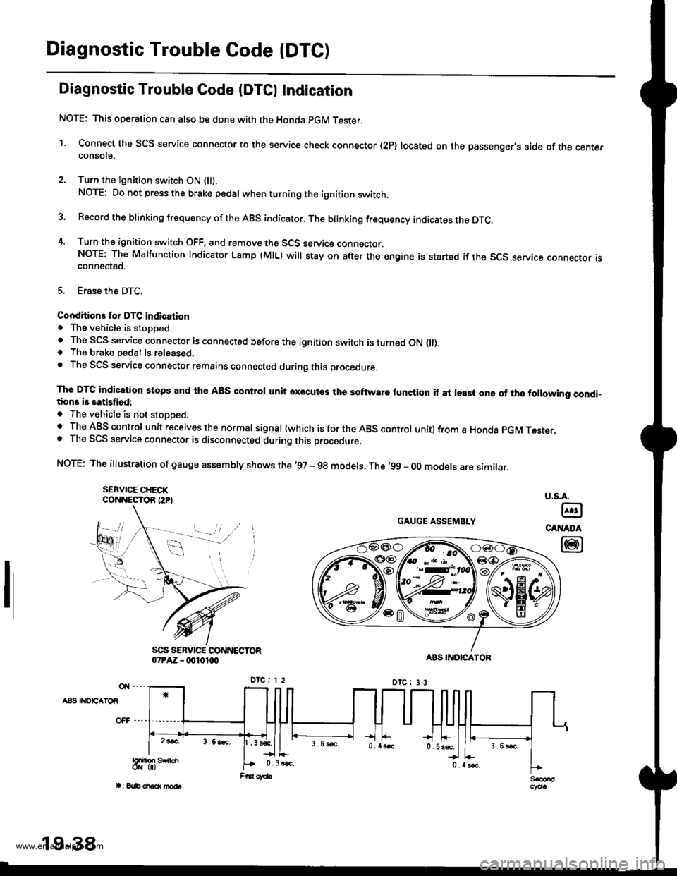
Diagnostic Trouble Code (DTC)
Diagnostic Trouble Gode IDTCI Indication
NOTE: This operation can also be done with the Honda pGM Tester.
1. Connect the SCS service connector to the service check connector (2P) located on the passenger's side of the centerconsote.
2. Turn the ignition switch ON (ll).
NOTE; Do not press the brake pedal whenturningthe ignition switch.
3 Record the blinking frequency of the ABS indicator. The brinking frequency indicates the DTc.
4. Turn the ignition switch OFF. and remove the SCS service connector.NOTE: The Malfunction Indicator Lamp (MlL) will stay on after the engine is startsd if the SCS seryica connecror rsconnected.
5. Erase the DTC.
Conditions for DTC indication. The vehicle is stopped.. The SCS service connector is connected before the ignition switch is turned ON flt).. The brake pedal is released.. The SCS service connector remains connected during this procedure.
The DTC indication stops and the ABS control unit axecutos tha softwaro lunction if at least one of tho following condi-tions i3 satisfiod:
. The vehicle is not stoooed.. The ABS control unit receives the normal signal (which is for the ABS control unit) from a Honda pGM Tesrer.. The SCS service connector is disconnectod during this procedure.
NQTE: The illustration of gauge assembly shows the '97 - 98 models. The '99 - oo models are similar.
SEFVICE CHECKCONNESTOR I2P}
GAUGE ASSEMBLY
A8S II{DEATOR
u.s.A.
@
CANADA
@
19-38
www.emanualpro.com