And HONDA CR-V 1999 RD1-RD3 / 1.G Workshop Manual
[x] Cancel search | Manufacturer: HONDA, Model Year: 1999, Model line: CR-V, Model: HONDA CR-V 1999 RD1-RD3 / 1.GPages: 1395, PDF Size: 35.62 MB
Page 718 of 1395
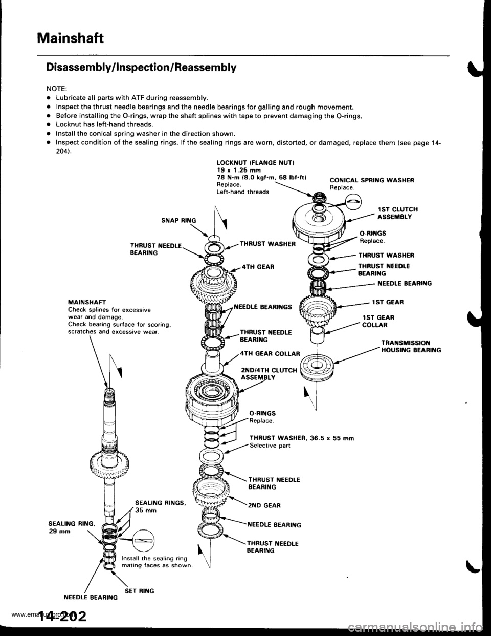
Mainshaft
Disassembly/lnspection/Reassembly
NOTE:
. Lubricate all parts with ATF during reassembly.
.Inspectthethrustneedlebearingsandtheneedlebearingsforgallingandroughmov\
ement,
. Before installing the O-rings. wrap the shaft splines with tape to prevent damaging the O-rings.. Locknut has left-hand threads.
. Install the conical spring washer in the direction shown.
. Inspect condition of the sealing rings. lf the sealing rings are worn, distorted, ordamaged, replace them (see page 14-
2041.
LOCKNUT IFLANGE NUT)19 x 1.25 mm78 N.m {8.O kgf.m,58 lbl.ftlReplace.Left-hand threads
CONICAL SPRING WASHERReplace.
lST CIUTCHASSEMBI.YSNAP RING
THRUST NEEDLEB€ARING
Install the sealing ringmating faces as shown
THRUST WASHEB
4TH GEAR
BEARII{GS
o-Brr{Gs
o-Rtt{GsReplace.
THRUST WASHCR
THRUST NEEOI€BEARIl{G
I{EEDLE BEARIIIG
lST GEARMAINSI{AFTCheck splines for excessivewear ano damage.Check bearing surface tor scoring,scratches and excessive wear.
rST GEARCOLLARTXBUST 1{EEDLEBEARIl{G
4TH GEAR COLLAR
2ND/4TH CLUTCX
TnANSMtSSIOt{HOUSII{G BEARII{G
THRUST WASHER, 36.5 r 55 mmSelective part
SEALING29 mm
THRUST NEEDLESEARING
2NO GEAR
NEEDLE EEARING
THRUST NEEDI-EBEARING
RltrlG,
NEEDLE EEARING
14-202
SET RING
www.emanualpro.com
Page 719 of 1395
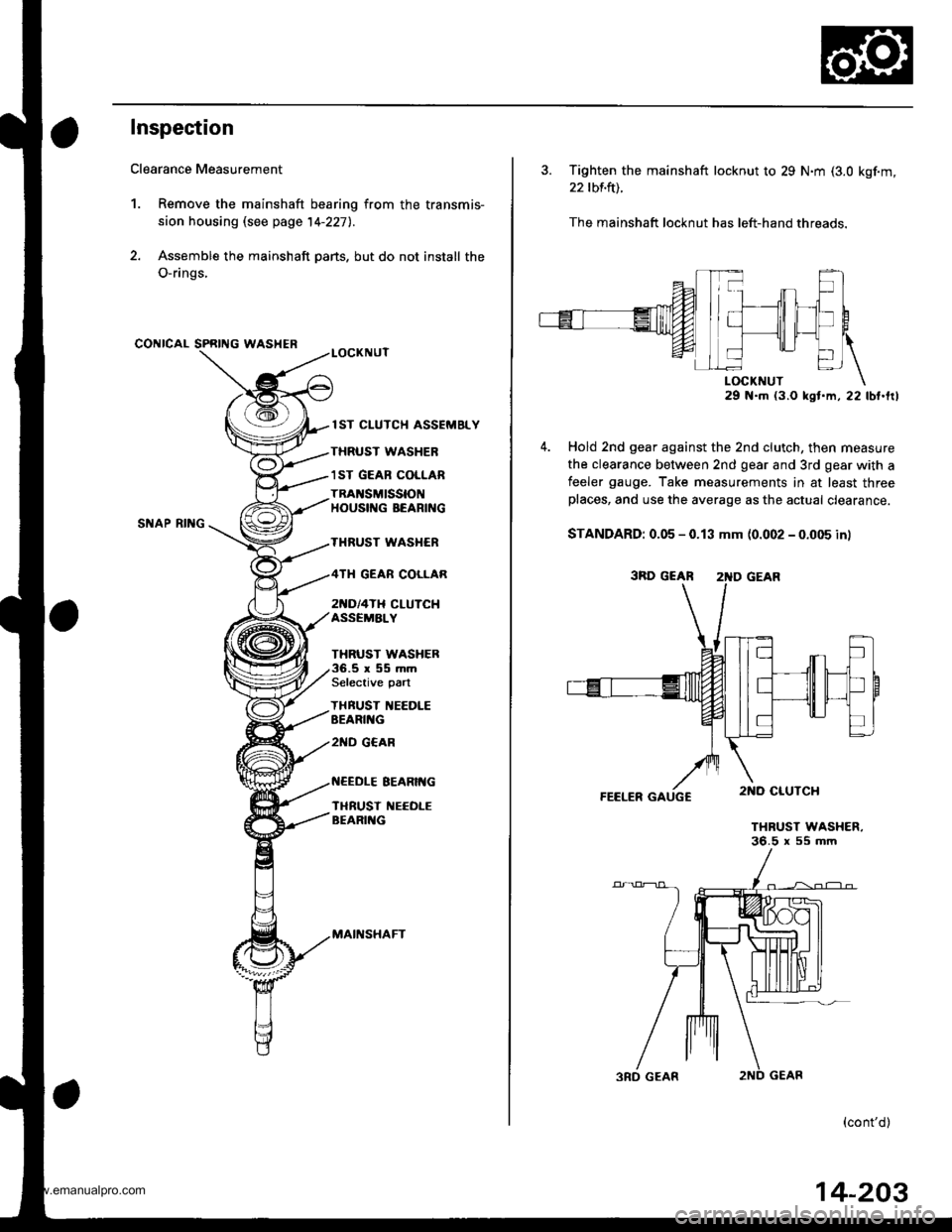
Inspection
Clearance Measurement
1. Remove the mainshaft bearing from the transmis-
sion housing lsee page 14-227l..
2. Assemble the mainshaft parts, but do not install the
O-rings,
CONICAL SPRING WASHER
SNAP RII{G
lST CLUTCH ASSEMELY
THRUST WASHER
1ST GEAB COLLAR
TRAI{SMISSIONHOUSIf{G BEARING
THRUST WASI{ER
2[{D/4TH CLUTCHASSEMALY
GEAR COLLAR
THRUST WASHER.5r55mmSelective part
THBUST IIEEDLEEEARII{G
2ND G€AR
EEARIt{G
TI{RUST NEEOLEBEARII{G
MAII{SHAFT
3. Tighten the mainshaft locknut to 29 N.m (3.0 kgf.m,
22 tbf.ft).
The mainshaft locknut has left-hand threads.
29 N.m (3.O kst.m, 22 lbt.frl
Hold 2nd gear against the 2nd clutch, then measure
the clearance between 2nd gear and 3rd gear with a
feeler gauge. Take measurements in at least threeplaces, and use the average as the actual clearance.
STANDARD: 0.05 - 0.13 mm (0.002 - 0.005 in)
FEELER GAUGC
THRUST WASHER.36.5 x 55 mm
(cont'd)
3RD GEAR 2'{D GEAR
14-203
www.emanualpro.com
Page 720 of 1395
MainshaftSealing Rings
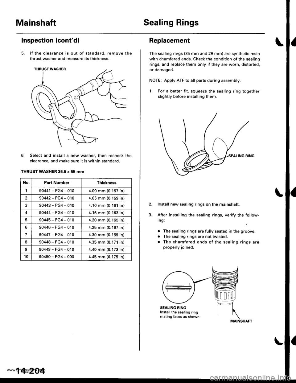
Inspection (cont'dl
It the clearance is out of standard, remove the
thrust washer and measure its thickness.
Select and install a new washer, then recheck the
clearance, and make sure it is within standard.
THRUST WASHER 36.5 x 55 mm
No.Part NumberThickness
190441 - PG4,0104.00 mm (0.157 in)
290442-PG4-0104.05 mm (0.159 in)
90443-PG4-0104.10 mm {0.161 in)
90444-PG4-0104.15 mm {0.163 in)
90445-PG4-0104.20 mm (0.'165 in)
690446-PG4-0104.25 mm {0.167 in)
190447-PG4-0104.30 mm (0.169 in)
890448-PG4-0104.35 mm (0.171 in)
I90449-PG4-0104.40 mm (0.173 in)
1090450-PG4-0004.45 mm (0.175 inl
14-204
Replacement
The sealing rings (35 mm and 29 mm) are synthetic resin
with chamfered ends. Check the condition of the sealing
rings, and replace them only if they are worn, distorted,
or oamageo.
NOTE: Apply ATF to all partsduring assembly.
1. For a better fit, squeeze the sealing ring together
slightly before installing them.
Install new sealing rings on the mainshaft.
After installing the sealing rings, verify the follow-
ing:
. The sealing rings are fully seated in the groove.
. The sealing rings are not twisted.
. The chamfered ends of the sealing rings are
properly joined.
SEALING RINGInstall the sealing ringmating faces as shown.
www.emanualpro.com
Page 721 of 1395
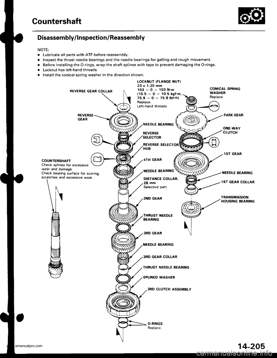
Countershaft
Disassembly/lnspection/Reassembly
NOTE:
. Lubricate all pans with ATF before reassembly.
.Inspectthethrustneedlebearingsandtheneedlebearingsforgallingandroughmov\
ement.
. Before installing the O-rings, wrap the shaft spllnes with tape to prevent damaging the O-rings.
. Locknut has left-hand threads.
. Install the conical spring washer in the direction shown.
R€VERSE GEAR
LOCKNUT IFLANGE NUTI23 x 1.25 mm103-0-103N.mCONICAL SPRINGWASHERReplace.t10.5 - 0 -
75.9 - 0 -
Replace.
10.5 kgl.m,75.9 lbt.lr)
Lelt.hand threads
COUNTERSHAFTCheck splines for excessivewear and damage.
REVERSE SELECTORHUB
4TH GEAR
NEEDLE EEARING
NEEOLE BEARING
REVERSESELECTOR
OISTANCE COLLAR.28 mmSelective part
2NO GEAR
lST GEAR
I{EEDLE BEARINGCheck bearing surface for scoring,scratches and excessive wear.lST GEAR COLLAR
TRANSn SSTONHOUSI G BEARING
3RD GEAR
NEEDLE BEARING
3RD GEAR COLLAR
THRUST NEEOLE BEARING
SPLINED WASHER
3RO CLUTCH ASS€MBLY
14-205
www.emanualpro.com
Page 722 of 1395
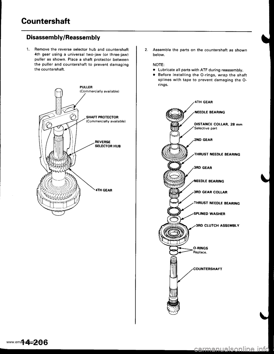
Gountershaft
Disassembly/Reassembly
1. Remove the reverse selector hub and countershaft
4th gear using a universal two-jaw lor three-jaw)
puller as shown. Place a shaft protector between
the puller and countershaft to prevent damaging
the countershaft.
{Commercially available)
REVERSESELECTOR HUB
.TH GEAR
14-206
2. Assemble the parts on the countershaft as shown
below.
NOTE;
. Lubricate all parts with ATF during reassembly.
. Before installing the O-rings. wrap the shaft
splines with tape to prevent damaging the O-
rings.
4TH GEAR
BEARI'{G
DISTANCE COLLAR, 28 mmSelective oart
GEAR
THRUST ]{EEOL€ AEARIIIG
GEAR COLLAR
THRUST I{EEDLE EEARII{G
WASHER
3RO CLUTCH ASSEMBLY
SEARII{G
O-RINGSReplace.
www.emanualpro.com
Page 723 of 1395
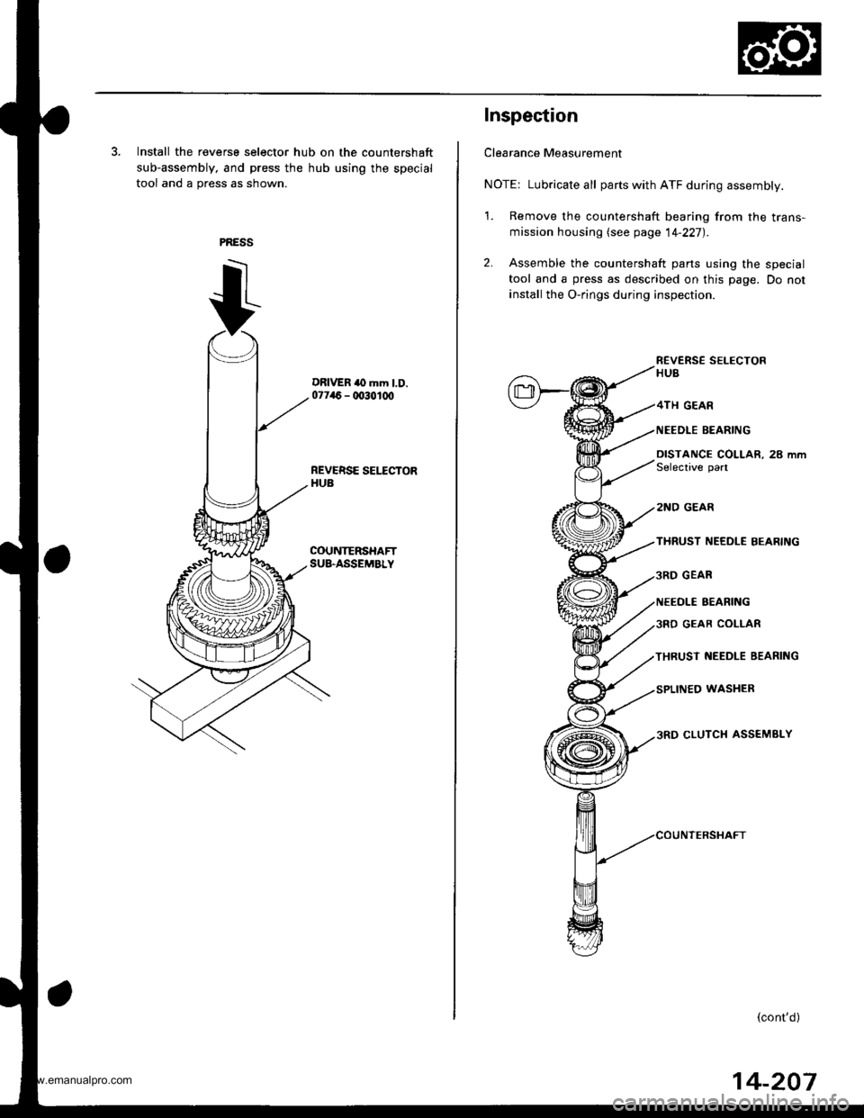
3. Install the reverse selector hub on the countershaft
sub-assembly, and press the hub using the special
tool and a press as shown.
DRIVER to mm l.D.07746 - 0030100
REVERSE SEI.ICTORHUB
COUNTERSHAFTSU&ASSEMBLY
Inspection
Clearance Measurement
NOTE: Lubricate all parts with ATF during assembly.
1. Remove the countershaft bearing from the trans-
mission housing lsee page 14-227).
2. Assemble the countershaft parts using the special
tool and a press as described on this page. Do not
install the O-rings during inspection.
R€VERS€ SELECTORHUB
GEAR
NEEDLE BEARING
DISTANCE COLLAR, 28 mmSelective part
2NO GEAR
THRUST NEEDLE BEARING
GEAR
NEEOLE BEARING
GEAR COLIAR
THRUST NEEDLE BEARING
WASHER
CLUTCH ASSEMBLY
(cont'd)
14-207
www.emanualpro.com
Page 724 of 1395
Countershaft
Inspection (cont'd)
3.
4.
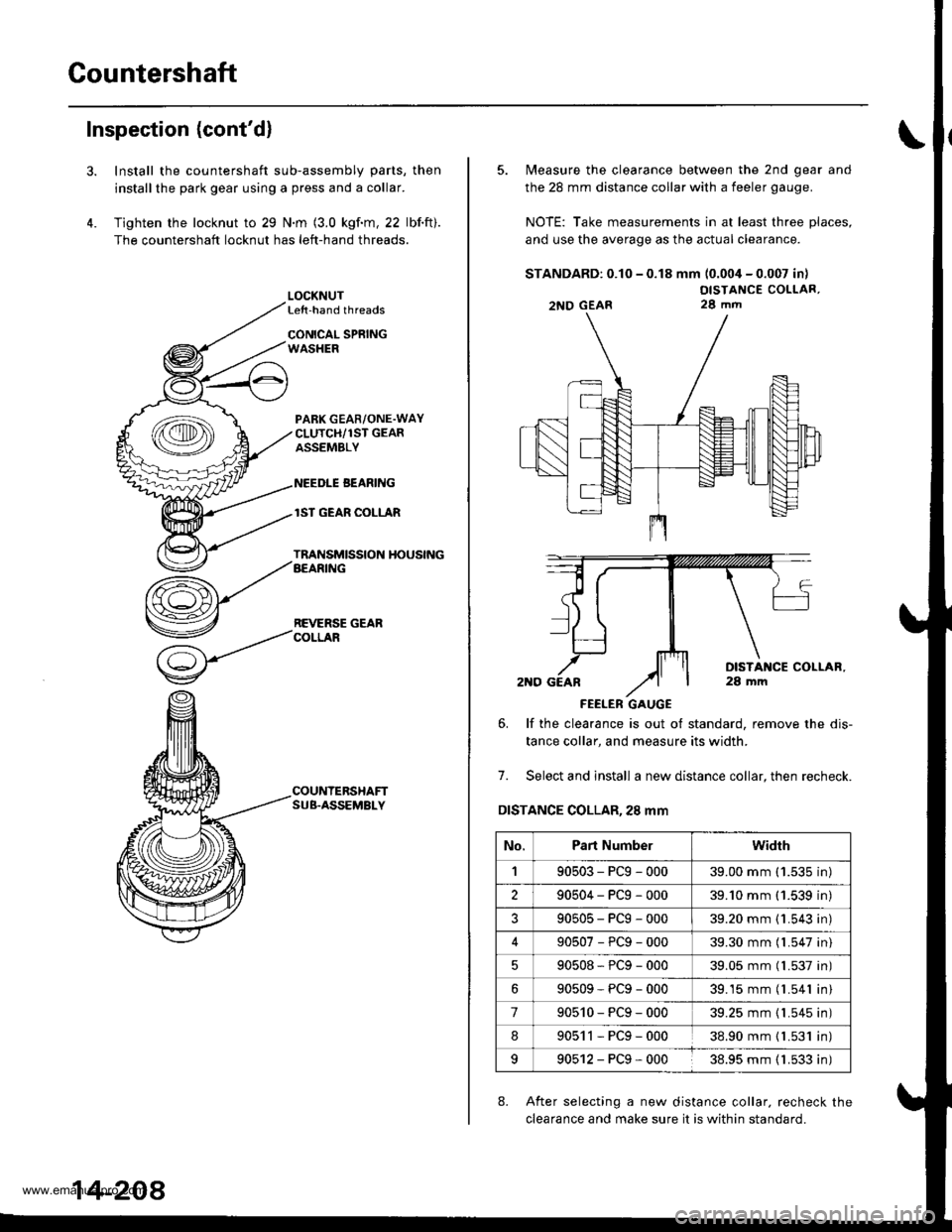
Install the countershaft sub-assembly parts, then
installthe park gear using a press and a collar.
Tighten the locknut to 29 N.m (3.0 kgf.m, 22 lbf.ft).
The countershaft locknut has left-hand threads.
LOCKNUTLe{t-hand threads
CONICAL SPRINGWASHER
PABK GEAR/ONE.WAYCLUTCH/1ST GEARASSEMBLY
NEEDLE BEANING
lST GEAR COLLAR
TRANSMISSION HOUSINGAEARING
REVERSE GEARCOLLAR
COUNTERSHAFTSUB.ASSEMBLY
14-208
5. Measure the clearance between the 2nd gear and
the 28 mm distance collar with a feeler gauge.
NOTE: Take measurements in at least three places,
and use the average as the actual clearance.
STANDARD: 0.10 - 0.18 mm (0.004 - 0.007 in)
OISTANCE COLLAR,28 mm
FEELER GAUGE
6. lf the clearance is out ot standard, remove the dis-
tance collar, and measure its width.
7. Select and install a new distance collar, then recheck.
DISTANCE COLLAR,28 mm
8. After selecting a new distance collar. recheck the
clearance and make sure it is within standard.
2NO GEAR
No.Part Numberwidrh
190503-PCg-00039.00 mm ('1.535 in)
290504-PCg-00039.'10 mm (1.539 in)
?90505-PCg-00039.20 mm {1.543 in)
90507-PCg-00039.30 mm (l.547 in)
90508*PCg-00039.05 mm (l.537 in)
90509-PCg-00039.15 mm (l.541 in)
790510-PCg-00039.25 mm {1.545 in)
890511-PCg-00038.90 mm { L531 in)
990512-PCg-00038.95 mm ( 1.533 in)
www.emanualpro.com
Page 725 of 1395
One-way Glutch
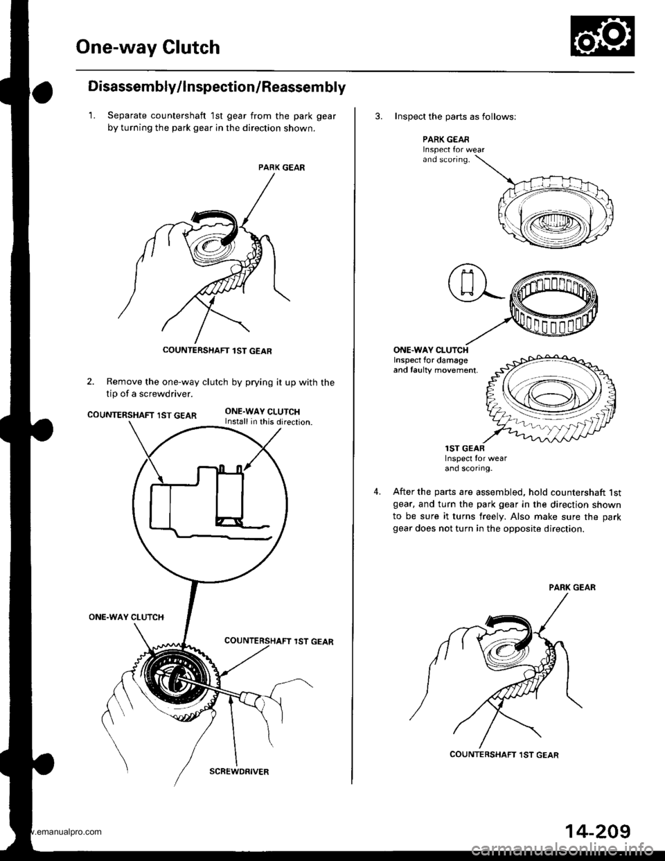
Disassembly/lnspection/Reassem bly
1. Separate countershaft 1st gear from the park gear
by turning the park gear in the direction shown.
PARK GEAR
2. Remove the one-way clutch by prying it up with the
tip of a screwdriver.
COUNTERSHAFT IST GEARONE.WAY CLUTCHInstall in this direction.
ONE.WAY CLUTCH
lST GEAR
COUNTERSHAFT lST GEAR
SCREWDRIVER
14-209
3. Inspect the oarts as follows;
PARK GEARInspect Ior wearand sconng.
ONE.WAY CLUTCHInspect for damageand taulty movement,
4.
lST GEARInspect for wearand scortng.
After the parts are assembled, hold countershaft lstgear. and turn the park gear in the direction shown
to be sure it turns freely. Also make sure the park
gear does not turn in the opposite direction.
COUNTERSHAFT ,IST GEAR
www.emanualpro.com
Page 726 of 1395
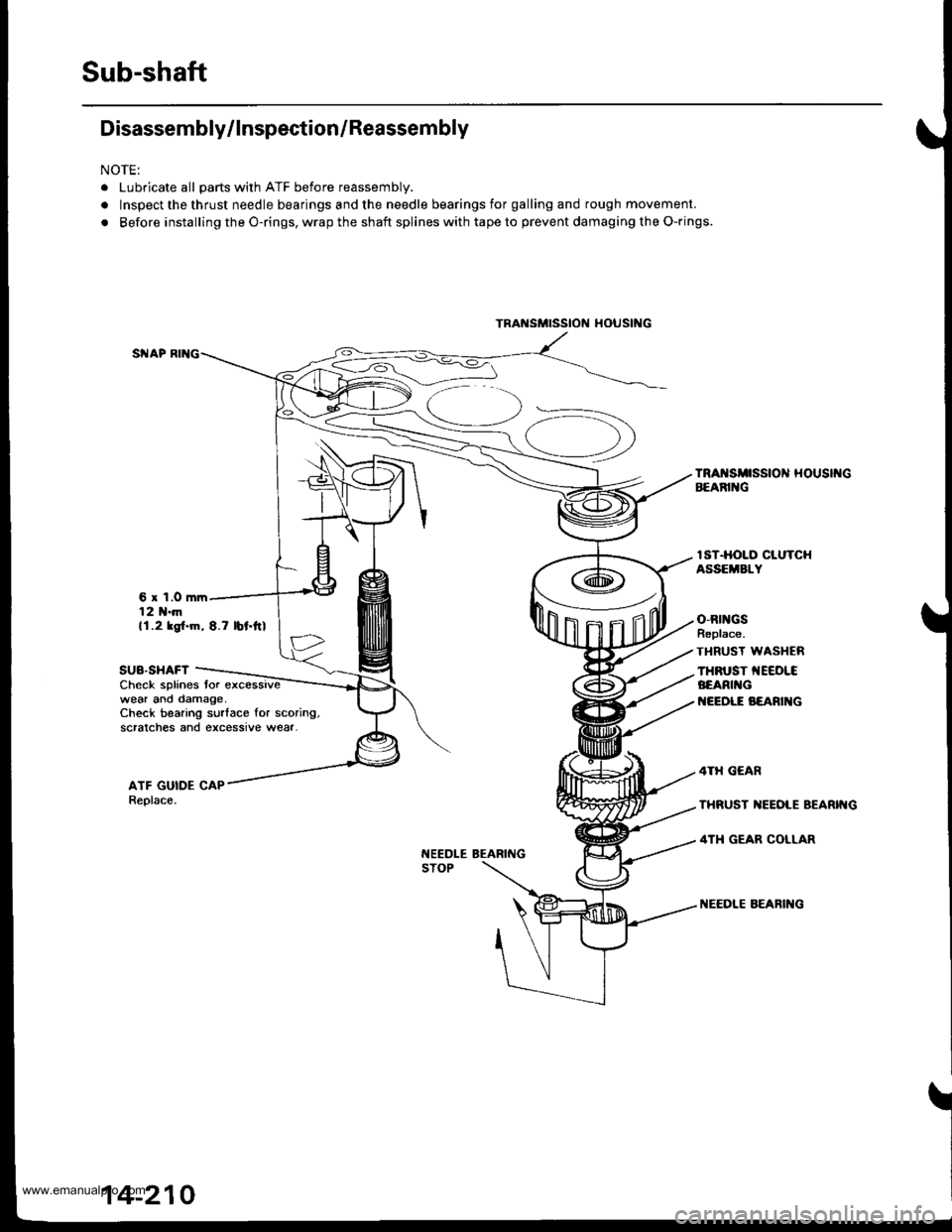
Sub-shaft
Disassembly/lnspection/Reassembly
NOTE:
. Lubricate all parts with ATF before reassembly.
. Inspect the thrust needle bearings and the needle bearings for galling and rough movement.
. Before installing the O-rings, wrap the shaft splines with tape to prevent damaging the O-rings.
6 x 1.0 mrr12 1{.mll.2 ksl.m, 8.7 lbt.ftl
SUB.SHAFTCheck splines tor excessivewear ano damage,Check bearing surlace for scoring,scralches and excessive wear-
t{EEDLE BEARINGSTOP
IST.HOLO CLUTCHASSEMBLY
o,Rtl{GSReplace.
TI{RUST WASI{ER
THFUST TEEOLCBEARI G
I{EEDLE B€ARI G
TRAi{SMTSStON tl()UStNG
14-210
www.emanualpro.com
Page 727 of 1395
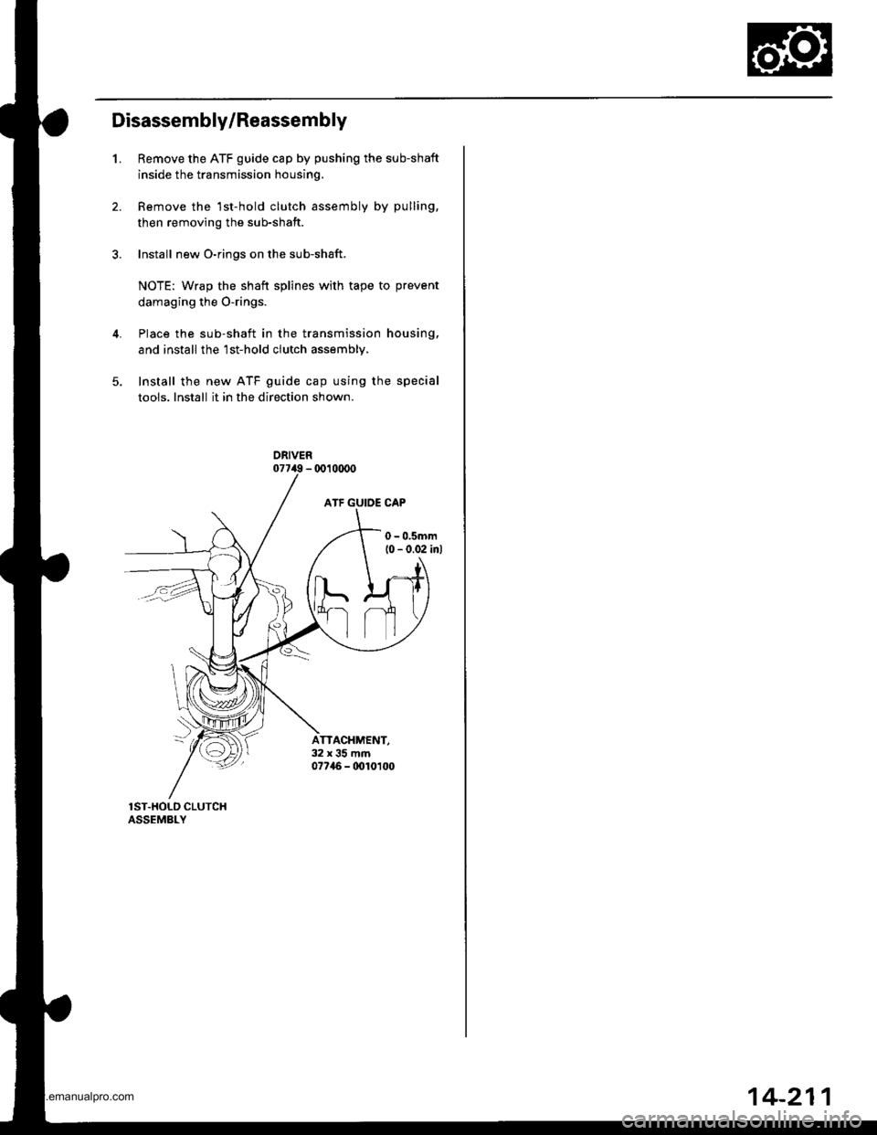
Disassembly/Reassembly
1.Remove the ATF guide cap by pushing the sub-shaft
inside the transmission housing.
Remove the 1st-hold clutch assembly by pulling,
then removing the sub-shaft.
Install new O-rings on the sub-shaft.
NOTE: Wrap the shaft splines with tape to prevent
damaging the O-rings.
Place the sub-shaft in the transmission housing,
and install the'lst-hold clutch assembly,
Install the new ATF guide cap using the special
tools. Install it in the direction shown.
ATTACHMENT,32x35mm07746 - 0010t00
14-211
www.emanualpro.com