Bolt HONDA CR-V 1999 RD1-RD3 / 1.G Workshop Manual
[x] Cancel search | Manufacturer: HONDA, Model Year: 1999, Model line: CR-V, Model: HONDA CR-V 1999 RD1-RD3 / 1.GPages: 1395, PDF Size: 35.62 MB
Page 14 of 1395
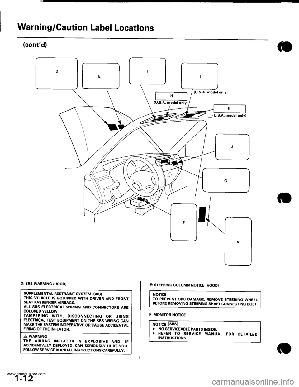
Warning/Caution Label Locations
(cont'dl
(U.S.A. modelonlyl
E: STEERING COLUMN NOTTCE tHOODI
NOTICETO PREVENT SRS DAMAGE, REMOVE STEERING WHEELBEFORE REMOVING STEERING SHAFT CONNECTING BOLT.
F: MONITOR NOTICE
NOTICE. NO SERVICEABLE PARTS tNStoE.. REFER TO SERVICE MANUAL FoR DETAILEDrNsrRucTtoNs.
{U.S.A. modol onlyl
o: SRS WARNING {HOOD}
SUPPLEMENTAL RESTRAINT SYSTEM {SRSITHIS VEHICLE IS EOUIPPED WITH DRIVER AND FRONTSEAT PASSENGER AIRBAGS,ALL SRS ELECTRICAL WIRING AND CONNECTORS ARECOLORED YELLOW.TAMPERING WITH, DISCONNECTING OR USINGELECTRICAL TEST EOUIPMENT ON THE SRS WIRING CANMAKE THE SYSTEM INOPERATIVE OR CAUSE ACCIDENTALFIRING OF THE INFLATOR.
A WARNINGTHE AIRBAG INFLATOR IS EXPLOSIVE AND. IFACCIDENTALLY DEPLOYED, CAN SEBIOUSLY HURT YOU.FOLLOW SERVICE MANUAL INSTRUCTIONS CAREFULLY.
1-12
www.emanualpro.com
Page 24 of 1395
Service Precautions
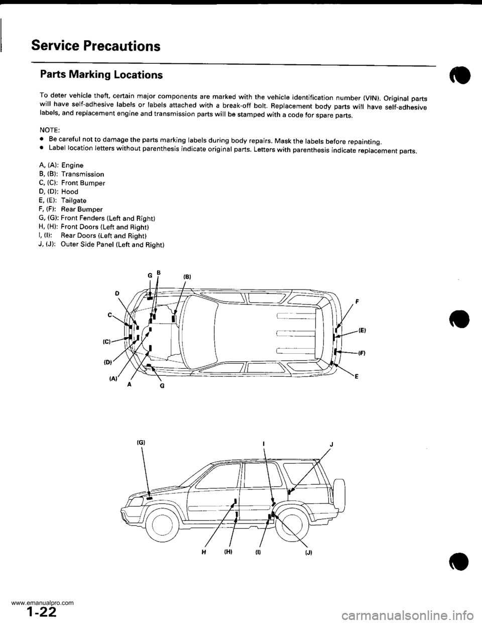
Parts Marking Locations
To deter vehicle theft, cenain major components are marked with the vehicle identification number {VlN). Original partswill have self-adhesive labels or labels attached with a break-off bolt. Replacement body parts will have self-adhesivelabels, and replacement engine and transmission parts will be stamped with a code tor spare parts.
NOTE:
. Be careful nottodamagethe parts marking labelsduring body repairs. Maskthe labels before repainting.' Label location letters without parenthesis indicate original parts. Letters with parenthesis indicate replacement pans.
A, (A): Engine
B, (B): Transmission
C, (C): Front Bumoer
D, (D); Hood
E, (E): Tailgate
F, (F): Rear Bumper
G, (G): Front Fenders (Lefr and Right)H, {H): Front Doors (Left and Right}
l, (l): Rear Doors (Left and Right)
J, (J): Outer Side Panel (Left and Right)
1-22
www.emanualpro.com
Page 57 of 1395
RE
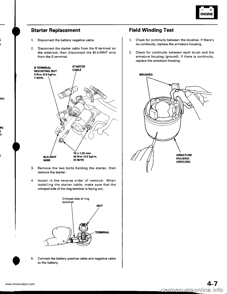
Starter Replacement
1.
B TERMINALMOUNNNG NUTI N.m (0.9 kgl.m,7 rbt ftl
Remove the two bolts holding the starter. then
remove the starter.
4. Install in the reverse order of removal. When
installing the starter cable, make sure that the
crimped side ofthe ring terminal is facing out,
Crimped side of ringterminal
TERMINAL
Connect the battery positive cable and negative cable
to the batterv.
Disconnect the battery negative cable.
Disconnect the starter cable from the B terminal on
the solenoid. then disconnect the BLK/WHT wire
from the S terminal.
STARTER
l0 x 1.25 mm4,1 N.m {4.5 kgf.m,33 tbt.ftl
5.
o
Field Winding Test
Check for continuity between the brushes. lf there's
no continuity, replace the armature housing,
Check for continuity between each brush and the
armature housing {ground). lf there is continuity.
replace the armature housing.
t.
ERUSHES
4-7
www.emanualpro.com
Page 66 of 1395

lgnition System
5.
lgnition Timing Inspection and Setting
2.
1.Check the idle speed, and adjust it if necessary (see
section 1 1).
Pull out the service check connector 2P (BRN and
BLK wires) from the connector holder located under
the dash on the front passenger side, then connect
the scs service connector (P/N 07PAz - 0010100) to
it.
Start the engine. Hold the engine at 3,000 rpm with
no load (A/T in N or E, Mff in neutral) until the
radiator fan comes on, then let it idle.
Connect the timing light to the No. I ignition wire,
then point the light toward the pointer on the timing
belt cover.
Check the ignition timing in no load conditions:
headlights, blower fan, rear window defogger, and
air conditioner are not operating.
lgnition Timing:
M/T: 16" 12" BTDC (RED) idling in neutral
AlTt'16" !2" BTDC (RED) idling in E or E
CRANKSHAFTPULLEY
4-16
6. lf necessary, adjust the ignition timing as follows.
Loosen the distributor mounting bolts, and turn the
distributor ignition (Dl) housing counterclockwise to
advance the timing or clockwise to retard the tim-
t no,
7.
8.
MOUNTING BOLTS24 N.m {2.4 kgf m, 17 lbtft}
Tighten the distributor mounting bolts, and recheck
the ignition timing.
Disconnect the SCS service connector from the ser-
vice check connector.
To RETARD
www.emanualpro.com
Page 67 of 1395
e
o
I'
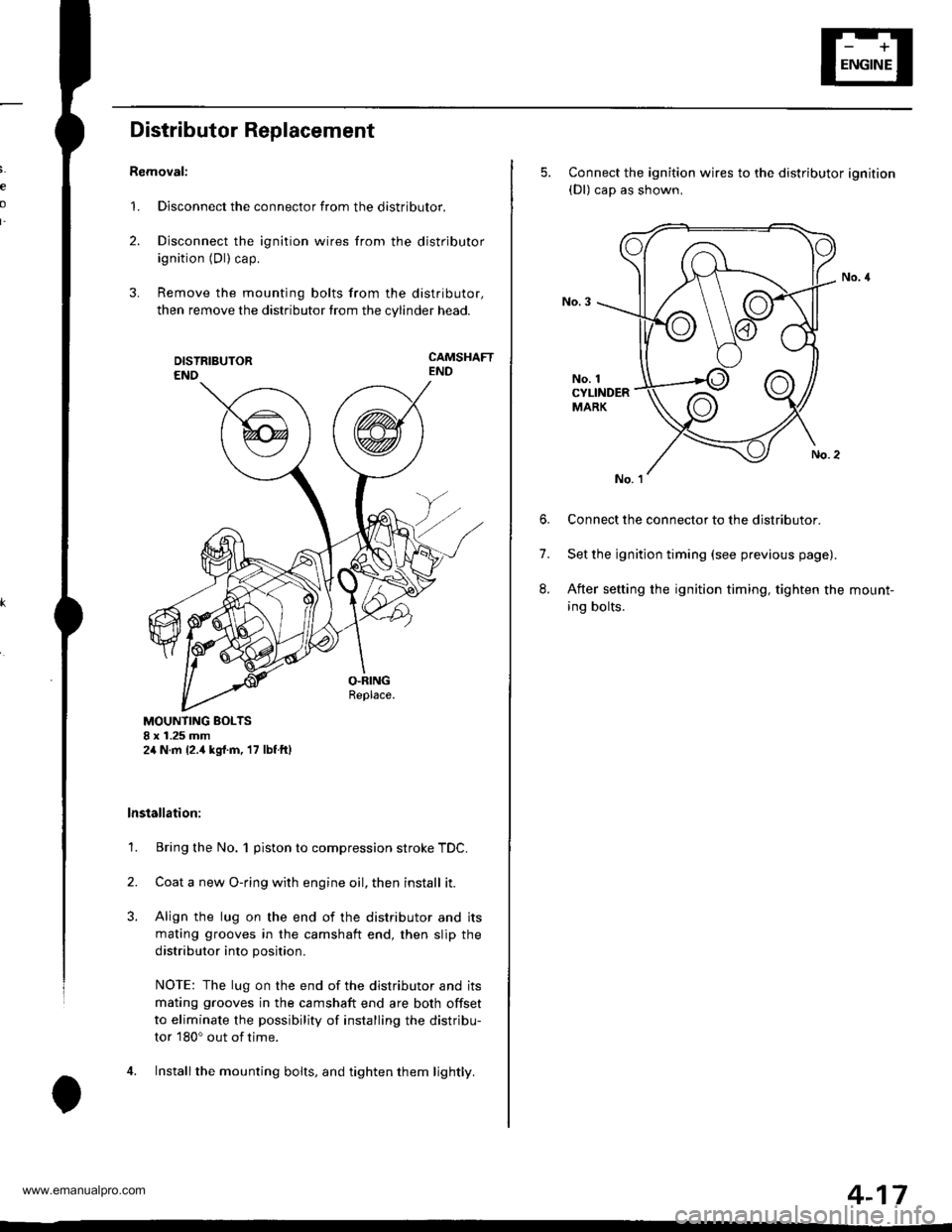
Distributor Replacement
Removal:
1. Disconnect the connector from the distributor.
2. Disconnect the ignition wires from the distributor
ignition (Dl) cap.
3. Remove the mounting bolts from the distributor,
then remove the distributor from the cylinder head.
CAMSHAFTEND
MOUNTING BOLTS8 x 1.25 mm2,1N.m {2.,1kgrf.m, 17 lbf ftl
lnstallation:
1. Bring the No. 1 piston to compression stroke TDC.
2. Coata new O-ring with engine oil, then install it.
3. Align the lug on the end of the distributor and its
mating grooves in the camshaft end, then slip the
distributor into position.
NOTE: The lug on the end of the distributor and its
mating grooves in the camshaft end are both offset
to eliminate the possibility of installing the distribu-
tor 180o out of time.
4. Installthe mounting bolts, and tighten them lightly.
5. Connect the ignition wires to the distributor ignition(Dl) cap as shown,
No. 1CYLINDERMARK
6. Connect the connector to the distributor.
7. Set the ignition timing (see previous page).
8. After setting the ignition timing, tighten the mount-
ing bolts.
4-17
www.emanualpro.com
Page 80 of 1395
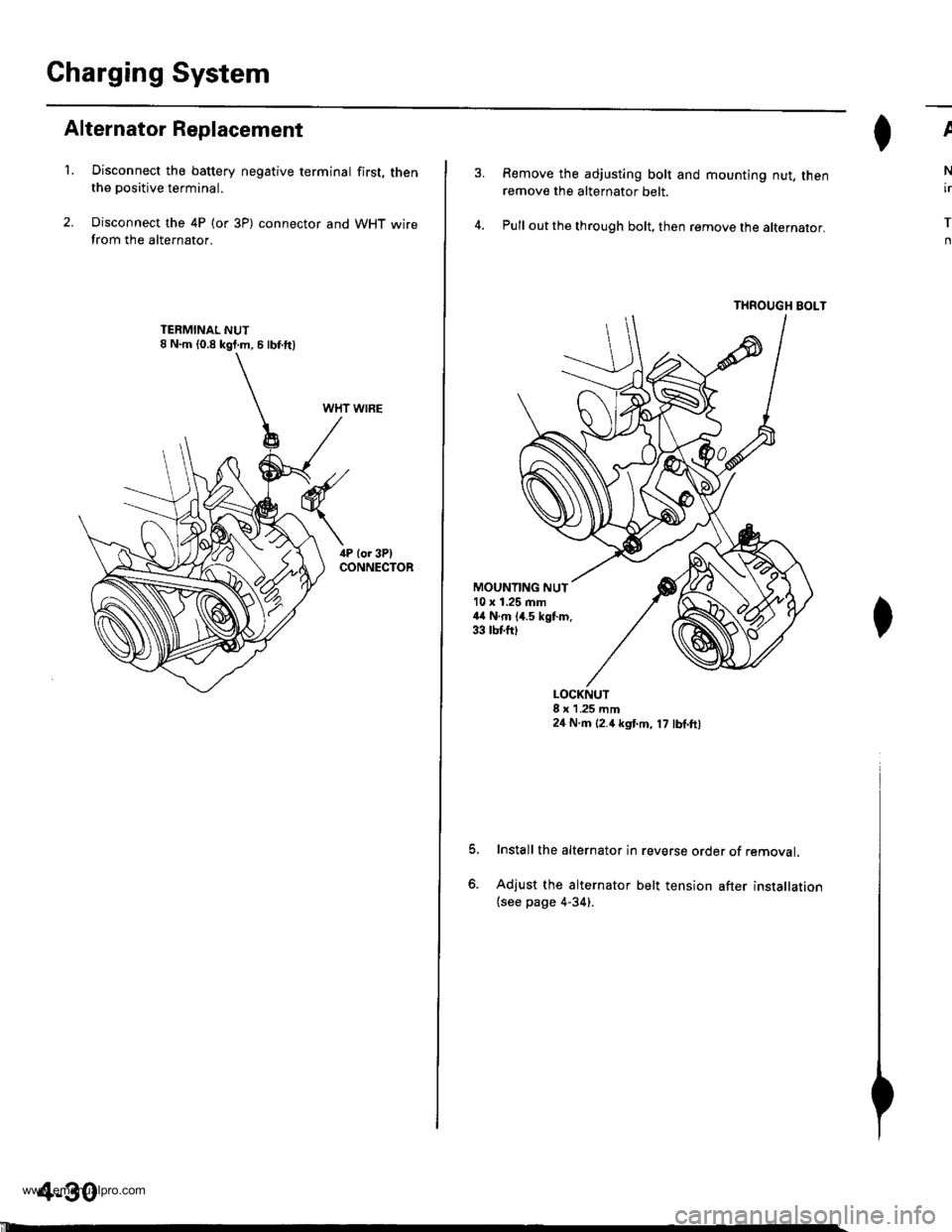
Charging System
Alternator Replacement
't.Disconnect the battery negative terminal first, thenthe positive terminal.
Disconnect the 4P (or 3P) connector and WHT wirefrom the alternator.
WHT WIRE
4-30
'll
Remove the adjusting bolt and mounting nut, thenremove the alternator belt.
Pull out the through bolt, then remove the alternator.
THROUGH BOLT
ll^I}v
N
ir
T
n
MOUNTING NUT10 x 1.25 mm44 N.m 14.5 kgf.m.33 tbtfttt
o.
LOCKNUT8 x 1 .25 mm24 N.m (2.4 kgt m, 17 lbl.ft,
Install the alternator in reverse order of removal.
Adjust the alternator belt tension after installation(see page 4-34).
www.emanualpro.com
Page 81 of 1395
,T
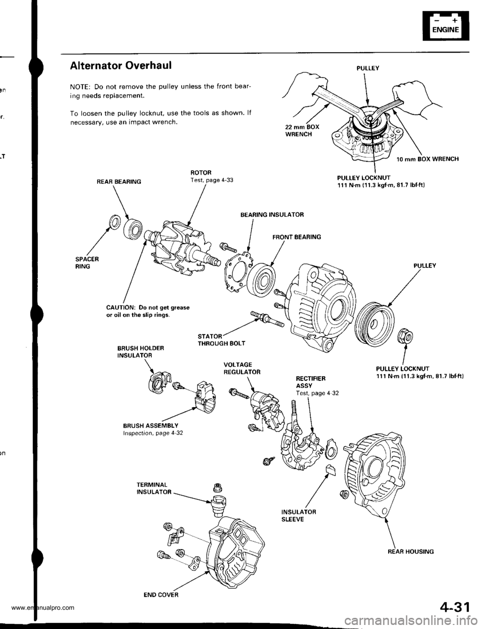
Alternator Overhaul
NOTE: Do not remove the pulley unless the front bear-
ing needs replacement.
To loosen the pulley locknut, use the tools as shown. lf
necessary, use an impact wrench.
PULLEY LOCKNUT111 N.m (11.3 kgf.m,81.7 lbf.ft)
FRONT BEARING
CAUTION: Do not get grease
or oil on the slip rings.
BRUSH HOLDERINSULATOB
"'^.^t%THROUGH BOLT
PULLEY
PULLEY LOCKNUT111 N.m {11.3 kgf.m, 81.7 lbf,ft)RECTIFIERASSYTest. page 4 32
PULLEY
BEARING INSULATOR
COVER
REAR HOUSING
4-31
www.emanualpro.com
Page 92 of 1395
Cruise Gontrol
Actuator Test (cont'dl
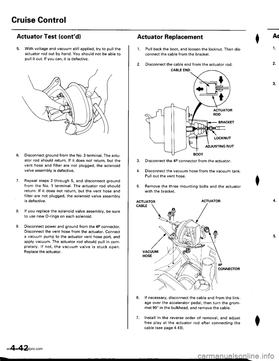
5. With voltage and vacuum still applied, try to pull the
actuator rod out by hand. You should not be able topull it out. lf you can. it is defectrve.
8.
9.
7.
Disconnect ground from the No. 3 terminal. The actu-
ator rod should return. lf it does not return, but the
vent hose and filter are not plugged, the solenoid
valve assembly is defective.
Repeat steps 2 through 5. and disconnect ground
from the No. l terminal. The actuator rod should
return. lf it does not return, but the vent hose and
filter are not plugged, the solenoid valve assembly
is defective.
lf you replace the solenoid valve assembly, be sure
to use new O-rings on each solenoid.
Disconnect power and ground from the 4P connector.
Disconnect the vent hose from the actuator. Connect
a vacuum pump to the actuator vent hose port, and
apply vacuum. The actuator rod should pull in com-pletely. lf not, the vacuum valve is stuck open.
Replace the actuator,
4-42
I
't.
Actuator Replacement
3.
4.
7.
Ar
Pull back the boot. and loosen the locknut. Then dis-
connect the cable from the bracket.
Disconnect the cable end from the actuator rod.
1.
4.
.J.
Disconnect the 4P connector from the actuator.
Disconnect the vacuum hose from the vacuum tank.
Pull out the vent hose.
Remove the three mounting bolts and the actuator
with the bracket.
ACTUATORACTUATOR
CABLE
lf necessary, disconnect the cable end from the link-
age over the accelerator pedal, then turn the grom-
met 90' in the bulkhead. and remove the cable.
Install in the reverse order of removal, and adjust
free play at the actuator rod after connecting the
cable (see page 4-43).
I
6.
I
www.emanualpro.com
Page 100 of 1395
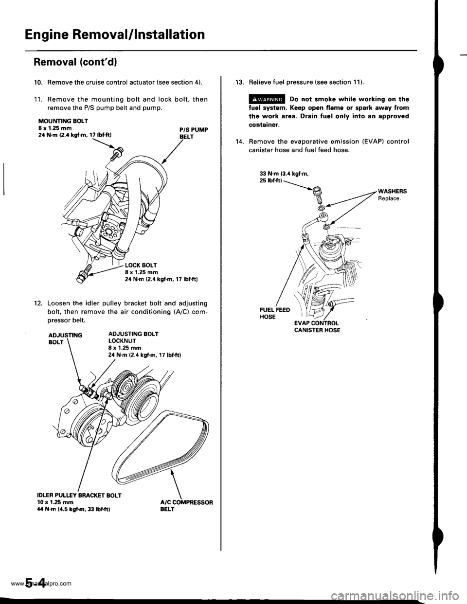
Engine Removal/lnstallation
Removal (cont'dl
Remove the cruise control actuator (see section 4).
Remove the mounting bolt and lock bolt, then
remove the P/S pump belt and pump.
10.
1t.
MOUNNNG BOLT8 x 1.25 mm2a N.m 12.4 kg{.m, 17 lbtftlP/S PUMPBELT
LOCK BOLTI x 1.25 mm24 N.m {2.4 kgtm, '17 lbf.ftl
12.Loosen the idler pulley bracket bolt and adjusting
bolt, then remove the air conditioning (A,/C) com-
pressor belt.
ID1TR PULI.f,Y ARACKET BOLT10 r 1.25 mma{ N.m 14.5lgtm,33 lbf.ft)
ADJUSTING BOLTLOCKNUT8 x 1.25 mm24 N.m {2.4 kgf.m, 17 lbf.ftl
5-4
13. Relieve fuel pressure {see section 11).
@ Do not 3mok6 whil€ working on th6
tugl systsm. Koep open flam€ or spark away from
the work area. Drain fuel only inlo an approved
container.
14. Remove the evaporative emission (EVAP) control
canister hose and tuel feed hose.
33 N.m (3.4 kgt.m,2s tbf.ft)
,%l
*ryft'fltr
\'t,f
EVAP CCCANISTER HOSE
www.emanualpro.com
Page 103 of 1395
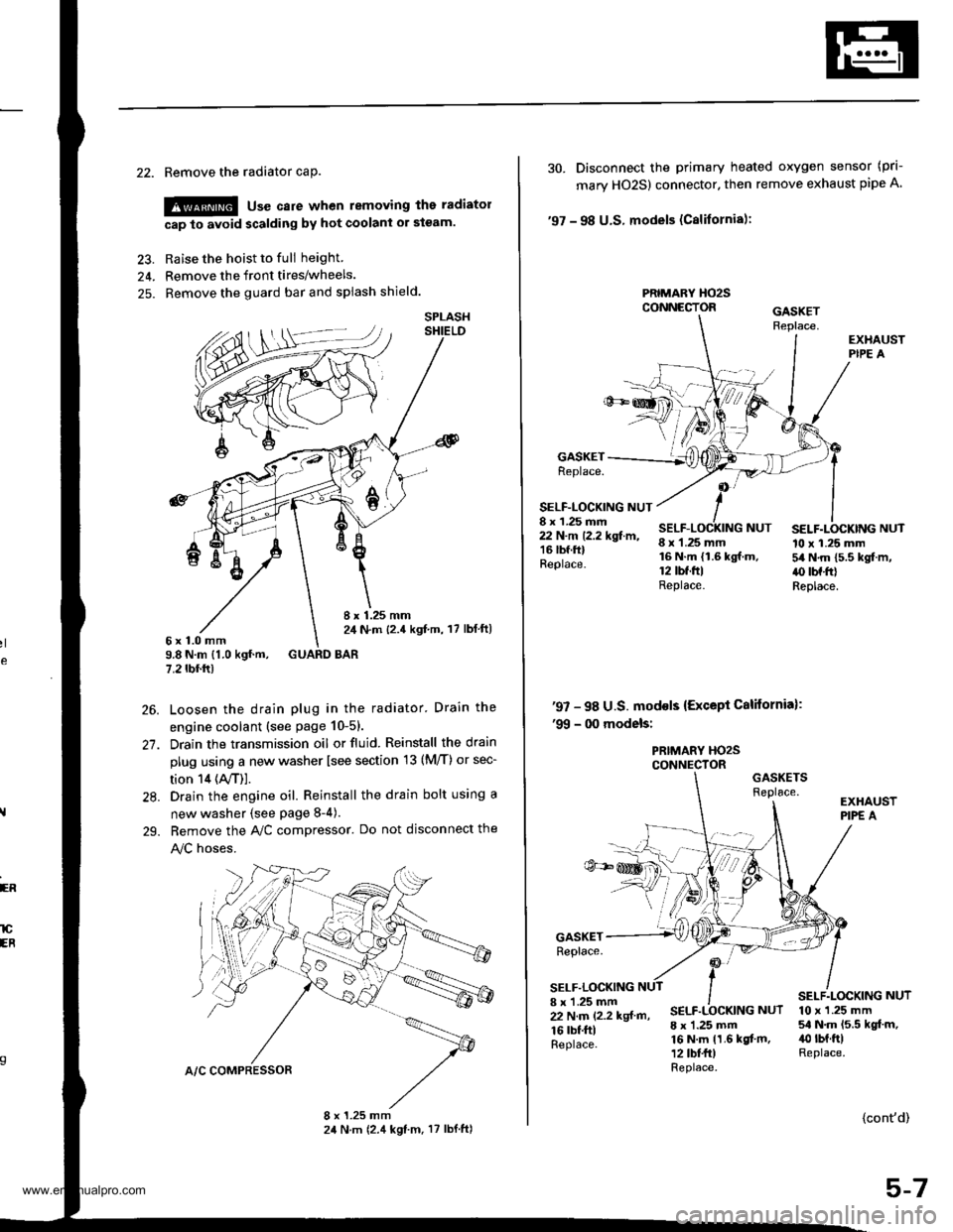
22. Remove the radiator caP.
!@ use care when removing the radiatol
cap to avoid scalding by hot coolani or steam.
23. Raise the hoist to full height
24. Remove the front tires/wheels.
25. Remove the guard bar and splash shield.
8 x 1.25 mm2,1 N.m {2.4 kgf,m, 17 lbl ft)6x1.0mm9.8 N.m {1.0 kgf.m, GUARD BAR7.2 tbf.rr)
Loosen the drain plug in the radiator. Drain the
engine coolant (see page 10-51.
Drain the transmission oil or fluid. Reinstall the drain
plug using a new washer lsee section 13 (M/T) or sec-
tion 14 (ly'T)].
Drain the engine oil. Reinstall the drain bolt using a
new washer {see page 8-4).
Bemove the A,/C compressor. Do not disconnect the
!y'C hoses.
SPLASH
26.
27.
28.
29.
ER
lCEB
30. Disconnect the primary heated oxygen sensor (prl-
mary HO2S) connector. then remove exhaust pipe A
'97 - 98 U.S. models (Cslifornia):
PRIMARY HO2SCONNECTOR
GASKETReplace.
SELF-LOCKING NUT8 x 1.25 mm22 N.m 12.2 kgf.m,16 lbf.ftlReplace.
8 x 1.25 mm16 N.m {1.6 kgf.m.12 tbt.ftlReplace.
SELF.LOCKING NUT10 x 1.25 mm54 N.m 15.5 kgf.m,.() tbf.frlReplace.
NUT
'97 - 98 U.S. mod€ls {Except California):'99 - 00 models:
PRIMARY HO2SCONNECTORGASKETSReplace.
GASKETReplace.
SELF.LOCKING8 x 'l.25 mm22 N.m (2.2 kgf m,
16 rbf.ftlReplace.
SELF.LOCKING NUT
8 x 1.25 mm16 N.m 11.6 kgf.m,12 tbt fr)Replace.
10 x 1.25 mm54 N.m 15.5 kgt.m,40 rbt.ftlReplace.
{cont'd)
5-7
www.emanualpro.com