clock HONDA CR-V 2000 RD1-RD3 / 1.G Owners Manual
[x] Cancel search | Manufacturer: HONDA, Model Year: 2000, Model line: CR-V, Model: HONDA CR-V 2000 RD1-RD3 / 1.GPages: 322, PDF Size: 4.64 MB
Page 55 of 322
Instrument
s an d Control s
Thi s sectio n give s informatio n abou t
th e control s an d display s tha t
contribut e to th e dail y operatio n o f
you r Honda . Al l th e essentia l
control s ar e withi n eas y reach .
Contro l Locations........................... . 5 2
Indicato r Lights............................... . 5 3
Gauges............................................. . 5 6
Speedometer............................... . 5 6
Tachometer................................. . 5 6
Odometer..................................... . 5 6
Tri p Meter................................... . 5 6
Fue l Gauge.................................. . 5 7
Temperatur e Gauge................... . 5 7
Maintenanc e Require d
Indicator................................... . 5 8
Control s Nea r th e Steerin g
Wheel....................................... . 5 9
Headlights................................... . 6 0 Daytim
e Runnin g Lights............ . 6 0
Instrumen t Pane l Brightness.... . 6 1
Tur n Signals................................ . 6 1
Windshiel d Wipers..................... . 6 2
Windshiel d Washers.................. . 6 2
Rea r Windo w Wipe r an d
Washer..................................... . 6 3
Hazar d Warning.......................... . 6 3
Rea r Windo w Defogger............. . 6 3
Steerin g Whee l Adjustment...... . 6 4
Steerin g Whee l Control s ............... . 6 6
Cruis e Control............................. . 6 6
Key s an d Locks............................... . 6 9
Keys.............................................. 69
Ignitio n Switch............................ . 6 9
Doo r Locks.................................. . 7 0
Powe r Doo r Locks...................... . 7 1
Remot e Transmitter................... . 7 2
Childproo f Doo r Locks.............. . 7 5
Tailgate........................................ . 7 5
Glov e Box.................................... . 7 7
Seats................................................. . 7 7
Fron t Sea t Adjustments............. . 7 7
Driver' s Sea t Heigh t
Adjustment.............................. . 7 8
Hea d Restraints.......................... . 7 9
Rea
r Seat-bac k Adjustment....... . 8 0
Rea r Sea t Armrest...................... . 8 0
Reclinin g th e Fron t an d
Rea r Seat-backs...................... . 8 1
Foldin g Rea r Seat....................... . 8 2
Powe r Windows.............................. . 8 4
Mirrors............................................. . 8 5
Adjustin g th e Powe r Mirrors.... . 8 6
Parkin g Brake................................. . 8 6
Digita l Clock.................................... . 8 7
Cente r Table.................................... . 8 7
Beverag e Holder............................. . 8 8
Built-i n Table................................... .
89
Cente r Pocket................................. .
9
1
Storag e Box..................................... . 9 1
Carg o Floo r Pockets....................... . 9 2
Accessor y Powe r Socket............... . 9 2
Tailgat e Pocket............................... . 9 3
Carg o Hooks...........,.,,..,,,.,...,,,........ . 9 3
Ashtrays........................................... . 9 4
Interio r Lights................................. . 9 4
Ceilin g Light................................ . 9 4
Spotlights..................................... 95
Carg o Are a Light........................ . 9 5
Ignitio n Switc h Light.................. . 9 5
Instrument s an d Control s
Page 77 of 322
Key
s an d Lock s
Panic Mode
Pani c mod e allow s yo u t o remotel y
activat e you r vehicle' s securit y
syste m to attrac t attention . Whe n
activated , th e hor n wil l soun d fo r
abou t 3 0 seconds . T o activat e pani c
mode , pres s an d hol d th e PANI C
butto n fo r abou t on e second .
T o cance l Pani c mod e befor e 3 0
seconds , pres s an y butto n o n th e
remot e transmitter . Yo u ca n als o
tur n th e ignitio n switc h t o O N (II) .
Pani c mod e wil l no t activat e if th e
ke y is i n th e ignitio n switch .
Replacing the Battery
Whe n th e remot e transmitter' s
batter y begin s t o ge t weak , i t ma y
tak e severa l pushe s o n th e butto n to
loc k o r unloc k th e doors , an d th e
LE D wil l ge t dim . Replac e th e
batter y a s soo n a s possible .
Batter y type : CR202 5
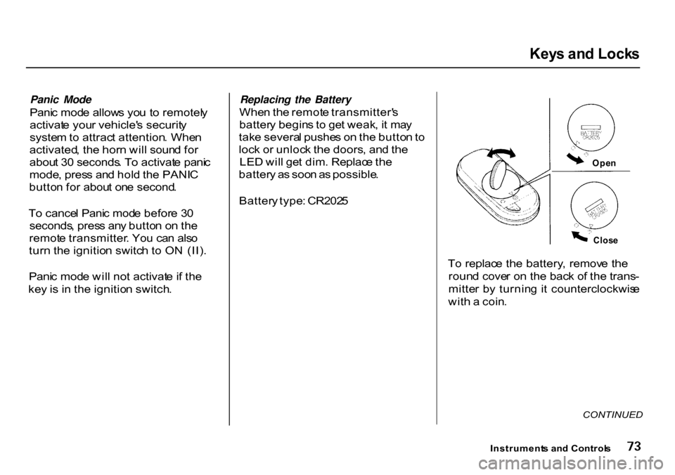
To replac e th e battery , remov e the
roun d cove r o n th e bac k o f th e trans -
mitte r b y turnin g i t counterclockwis e
wit h a coin .
Instrument s an d Control s
Clos
e
Ope
n
CONTINUED
Page 78 of 322
Key
s an d Lock s
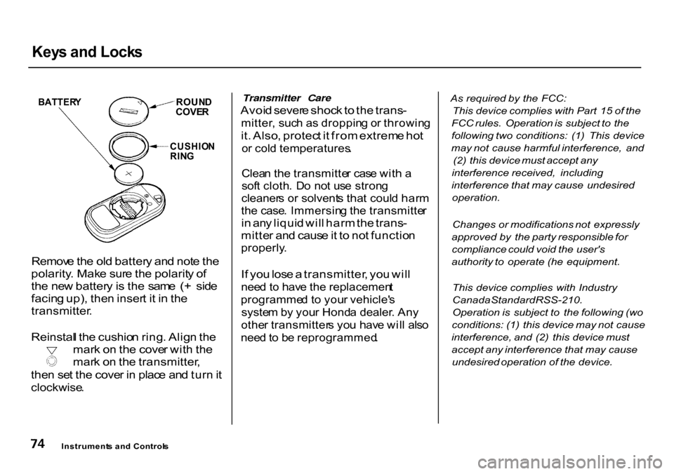
Remov e th e ol d batter y an d not e th e
polarity . Mak e sur e th e polarit y o f
th e ne w batter y is th e sam e ( + sid e
facin g up) , the n inser t i t i n th e
transmitter .
Reinstal l th e cushio n ring . Alig n th e mar
k o n th e cove r wit h th e mar
k o n th e transmitter ,
the n se t th e cove r i n plac e an d tur n it
clockwise .
Transmitter Care
Avoi d sever e shoc k to th e trans -
mitter , suc h a s droppin g o r throwin g
it . Also , protec t i t fro m extrem e ho t
o r col d temperatures .
Clea n th e transmitte r cas e wit h a
sof t cloth . D o no t us e stron g
cleaner s o r solvent s tha t coul d har m
th e case . Immersin g th e transmitte r
i n an y liqui d wil l har m th e trans -
mitte r an d caus e it t o no t functio n
properly .
I f yo u los e a transmitter , yo u wil l
nee d to hav e th e replacemen t
programme d t o you r vehicle' s
syste m by you r Hond a dealer . An y
othe r transmitter s yo u hav e wil l als o
nee d to b e reprogrammed .
As
required by the FCC:
This device complies with Part 15 of the
FCC rules. Operation is subject to the
following two conditions: (1) This device
may not cause harmful interference, and
(2) this device must accept any
interference received, including
interference that may cause undesired
operation.
Changes or modifications not expressly
approved by the party responsible for
compliance could void the user's
authority to operate (he equipment.
This device complies with Industry
Canada Standard RSS-210.
Operation is subject to the following (wo
conditions: (1) this device may not cause
interference, and (2) this device must
accept any interference that may cause
undesired operation of the device.
Instrument s an d Control s
BATTER
Y
ROUND
COVE R
CUSHIO N
RIN G
Page 91 of 322
Digita
l Clock , Cente r Tabl e
Digita l Cloc k
R (RESET )
Th e digita l cloc k display s th e tim e
wit h th e ignitio n switc h O N (II) .
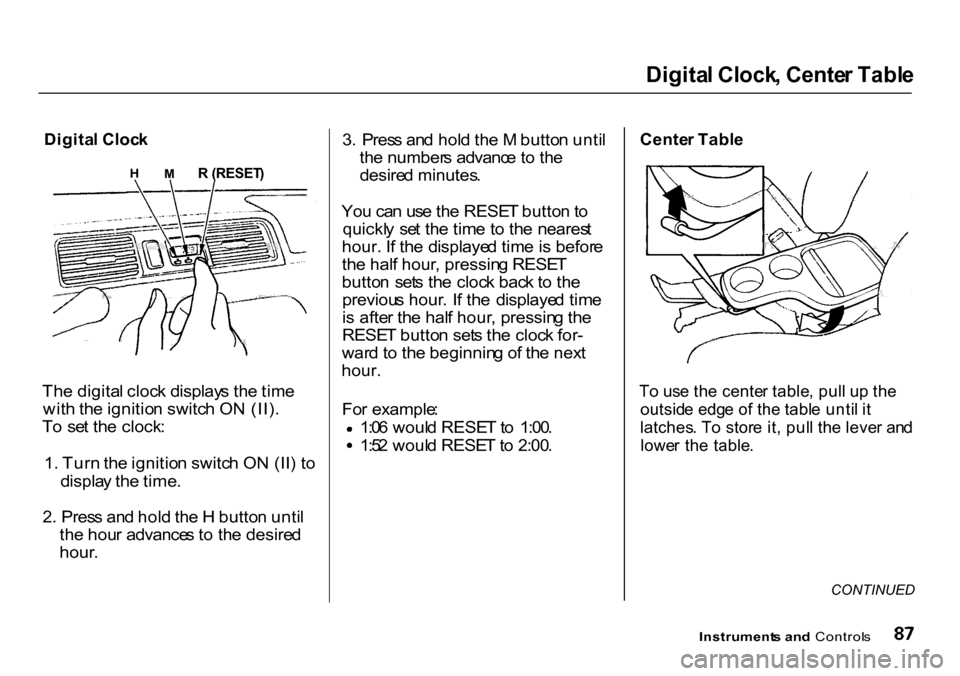
T o se t th e clock :
1 . Tur n th e ignitio n switc h O N (II ) t o
displa y th e time .
2 . Pres s an d hol d th e H butto n unti l
th e hou r advance s t o th e desire d
hour . 3
. Pres s an d hol d th e M butto n unti l
th e number s advanc e to th e
desire d minutes .
Yo u ca n us e th e RESE T butto n to
quickl y se t th e tim e t o th e neares t
hour. If th e displaye d tim e is befor e
th e hal f hour , pressin g RESE T
butto n set s th e cloc k bac k t o th e
previou s hour . I f th e displaye d tim e
i s afte r th e hal f hour , pressin g th e
RESE T butto n set s th e cloc k for -
war d to th e beginnin g o f th e nex t
hour.
Fo r example : 1:0
6 woul d RESE T to 1:00 . 1:5
2 woul d RESE T to 2:00 .
Cente
r Tabl e
T o us e th e cente r table , pul l u p th e
outsid e edg e o f th e tabl e unti l i t
latches . T o stor e it , pul l th e leve r an d
lowe r th e table .
CONTINUED
Instrument s an d Control s
H
M
Page 102 of 322
Heatin
g an d Coolin g
Prope r us e o f th e Heatin g an d
Coolin g syste m ca n mak e th e
interio r dr y an d comfortable , an d
kee p th e window s clea r fo r bes t
visibility .
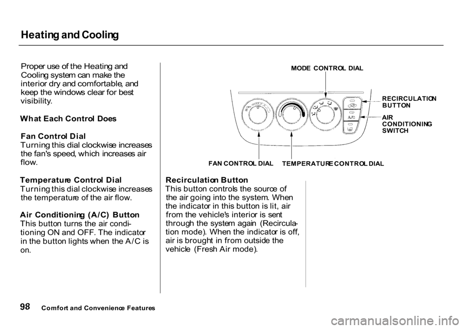
Wha t Eac h Contro l Doe s
Fa n Contro l Dia l
Turnin g thi s dia l clockwis e increase s
th e fan' s speed , whic h increase s ai r
flow .
Temperatur e Contro l Dia l
Turnin g thi s dia l clockwis e increase s
th e temperatur e o f th e ai r flow .
Ai r Conditionin g (A/C ) Butto n
Thi s butto n turn s th e ai r condi -
tionin g O N an d OFF . Th e indicato r
i n th e butto n light s whe n th e A/ C is
on .
Recirculatio
n Butto n
Thi s butto n control s th e sourc e o f
th e ai r goin g int o th e system . Whe n
th e indicato r i n thi s butto n is lit , ai r
fro m th e vehicle' s interio r i s sen t
throug h th e syste m agai n (Recircula -
tio n mode) . Whe n th e indicato r i s off ,
ai r i s brough t i n fro m outsid e th e
vehicl e (Fres h Ai r mode) .
Comfor t an d Convenienc e Feature s MOD
E CONTRO L DIA L
RECIRCULATIO N
BUTTO N
AI R
CONDITIONIN G
SWITC H
TEMPERATUR E CONTRO L DIA L
FA
N CONTRO L DIA L
Page 206 of 322
Coolin
g Syste m
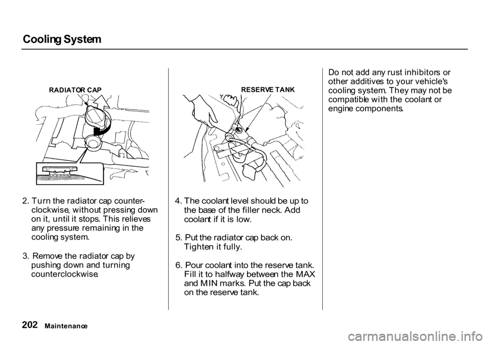
RADIATO R CA P
2 . Tur n th e radiato r ca p counter -
clockwise , withou t pressin g dow n
o n it , unti l i t stops . Thi s relieve s
an y pressur e remainin g in th e
coolin g system .
3 . Remov e th e radiato r ca p b y
pushin g dow n an d turnin g
counterclockwise . RESERV
E TAN K
4 . Th e coolan t leve l shoul d b e u p to
th e bas e o f th e fille r neck . Ad d
coolan t i f i t i s low .
5 . Pu t th e radiato r ca p bac k on .
Tighte n i t fully .
6 . Pou r coolan t int o th e reserv e tank .
Fil l i t t o halfwa y betwee n th e MA X
an d MI N marks . Pu t th e ca p bac k
o n th e reserv e tank .
D
o no t ad d an y rus t inhibitor s o r
othe r additive s t o you r vehicle' s
coolin g system . The y ma y no t b e
compatibl e wit h th e coolan t o r
engin e components .
Maintenanc e
Page 207 of 322
Coolin
g Syste m
Replacin g Engin e Coolan t
Th e coolin g syste m shoul d b e
completel y draine d an d refille d wit h
ne w coolan t accordin g t o th e tim e
an d distanc e recommendation s i n
th e maintenanc e schedule . Onl y us e
Genuin e Hond a Antifreeze/Coolant .
Drainin g th e coolan t require s acces s
t o th e undersid e o f th e vehicle .
Unles s yo u hav e th e tool s an d
knowledge , yo u shoul d hav e thi s
maintenanc e don e b y a skille d
mechanic .
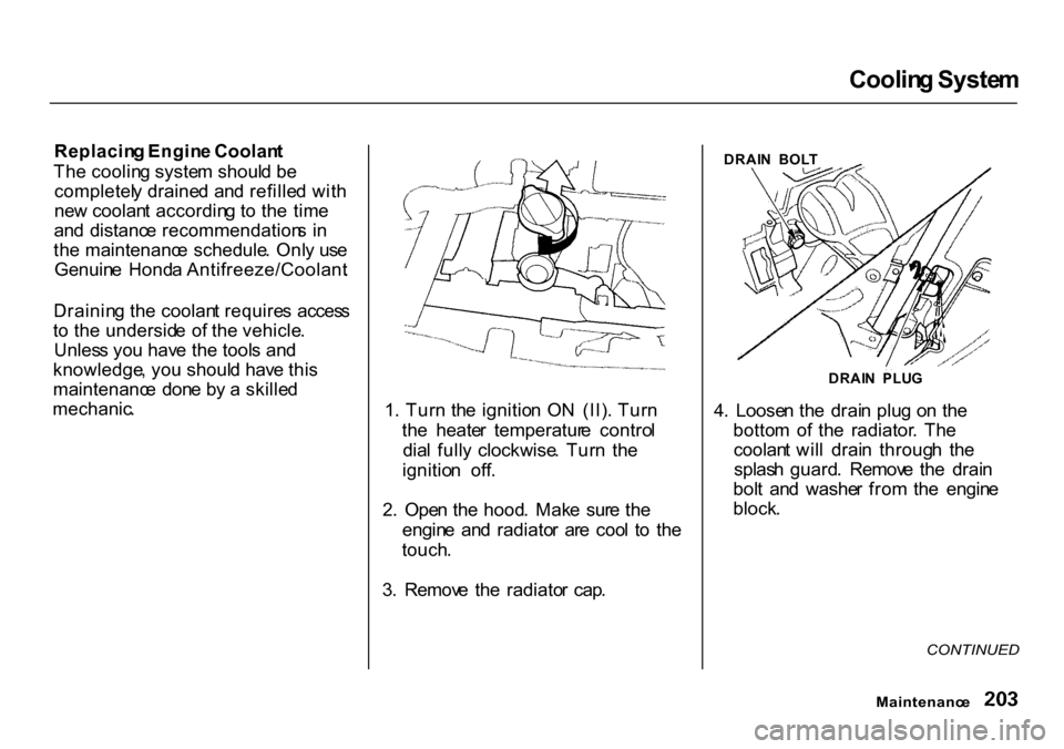
1. Tur n th e ignitio n O N (II) . Tur n
th e heate r temperatur e contro l
dia l full y clockwise . Tur n th e
ignitio n off .
2 . Ope n th e hood . Mak e sur e th e
engin e an d radiato r ar e coo l t o th e
touch .
3 . Remov e th e radiato r cap . 4
. Loose n th e drai n plu g o n th e
botto m o f th e radiator . Th e
coolan t wil l drai n throug h th e
splas h guard . Remov e th e drai n
bol t an d washe r fro m th e engin e
block .
CONTINUED
Maintenanc e
DRAI
N BOL T
DRAI N PLU G
Page 238 of 322
Light
s
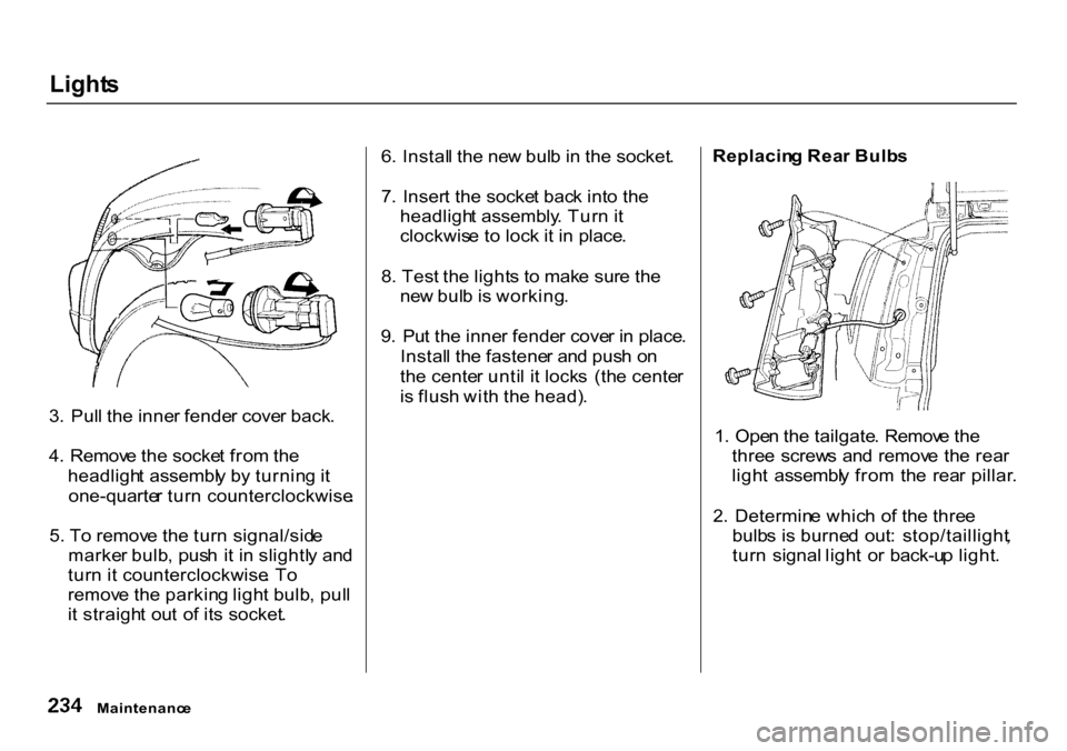
3 . Pul l th e inne r fende r cove r back .
4 . Remov e th e socke t fro m th e
headligh t assembl y b y turnin g it
one-quarte r tur n counterclockwise .
5 . T o remov e th e tur n signal/sid e
marke r bulb , pus h i t i n slightl y an d
tur n i t counterclockwise . T o
remov e th e parkin g ligh t bulb , pul l
i t straigh t ou t o f it s socket . 6
. Instal l th e ne w bul b in th e socket .
7 . Inser t th e socke t bac k int o th e
headligh t assembly . Tur n it
clockwis e t o loc k i t i n place .
8 . Tes t th e light s t o mak e sur e th e
ne w bul b is working .
9 . Pu t th e inne r fende r cove r i n place .
Instal l th e fastene r an d pus h o n
th e cente r unti l i t lock s (th e cente r
i s flus h wit h th e head) . Replacin
g Rea r Bulb s
1 . Ope n th e tailgate . Remov e th e
thre e screw s an d remov e th e rea r
ligh t assembl y fro m th e rea r pillar .
2 . Determin e whic h o f th e thre e
bulb s i s burne d out : stop/taillight ,
tur n signal light o r back-u p light .
Maintenanc e
Page 239 of 322
Light
s
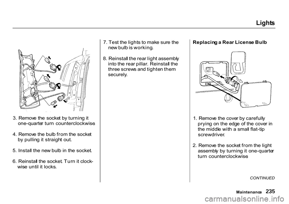
3 . Remov e th e socke t b y turnin g it
one-quarte r tur n counterclockwise .
4 . Remov e th e bul b fro m th e socke t
b y pullin g it straigh t out .
5 . Instal l th e ne w bul b in th e socket .
6 . Reinstal l th e socket . Tur n it clock -
wis e unti l i t locks . 7
. Tes t th e light s t o mak e sur e th e
ne w bul b is working .
8 . Reinstal l th e rea r ligh t assembl y
int o th e rea r pillar . Reinstal l th e
thre e screw s an d tighte n the m
securely .
Replacin
g a Rea r Licens e Bul b
1 . Remov e th e cove r b y carefull y
pryin g o n th e edg e o f th e cove r i n
th e middl e wit h a smal l flat-ti p
screwdriver .
2 . Remov e th e socke t fro m th e ligh t
assembl y b y turnin g it one-quarte r
tur n counterclockwise .
CONTINUED
Maintenanc e
Page 240 of 322
Light
s
3 . Pul l th e bul b straigh t ou t o f it s
socket . Pus h th e ne w bul b in unti l
i t bottom s in th e socket .
4 . Tur n o n th e parkin g light s an d
chec k tha t th e ne w bul b is
working .
5 . Reinstal l th e socket . Sna p th e
cove r bac k in place .
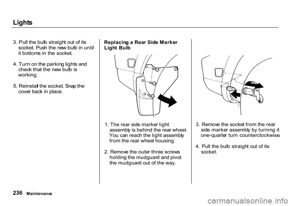
Replacin
g a Rea r Sid e Marke r
Ligh t Bul b
1 . Th e rea r sid e marke r ligh t
assembl y is behin d th e rea r wheel .
Yo u ca n reac h th e ligh t assembl y
fro m th e rea r whee l housing .
2 . Remov e th e oute r thre e screw s
holdin g th e mudguar d an d pivo t
th e mudguar d ou t o f th e way . 3
. Remov e th e socke t fro m th e rea r
sid e marke r assembl y b y turnin g i t
one-quarte r tur n counterclockwise .
4 . Pul l th e bul b straigh t ou t o f it s
socket.
Maintenanc e