Bearing HONDA CR-V 2000 RD1-RD3 / 1.G Workshop Manual
[x] Cancel search | Manufacturer: HONDA, Model Year: 2000, Model line: CR-V, Model: HONDA CR-V 2000 RD1-RD3 / 1.GPages: 1395, PDF Size: 35.62 MB
Page 844 of 1395
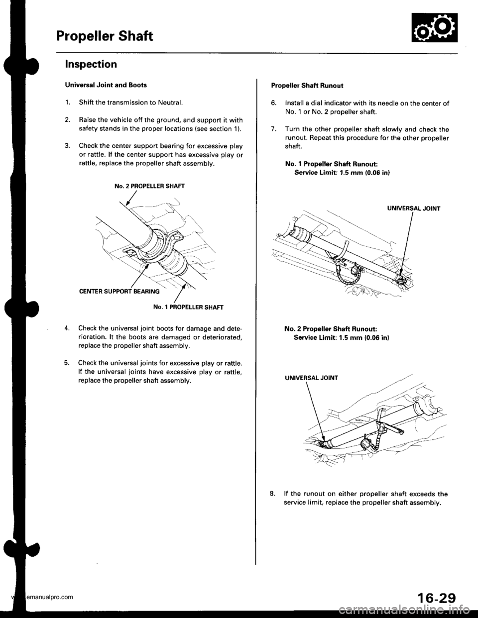
Propeller Shaft
Inspection
Univarsal Joint and Boots
1. Shift the transmission to Neutral.
2. Raise the vehicle off the ground, and support it with
safety stands in the proper locations (see section 1).
3. Check the cente. support bearing for excessive play
or rattle. It the center support has excessive play or
raftle, replace the propeller shaft assembly.
No. 1 PROPET_LER SHAFT
Check the universal joint boots for damage and dete-
rioration. lt the boots are damaged or deteriorated,
replace the propeller shaft assembly.
Check the universal joints for excessive play or rattle.
lf the universal joints have excessive play or rattle,
replace the propeller shaft assembly.
Propellor Shaft Runout
6. Install a dial indicator with its needle on the center of
No, 1 or No.2 propeller shaft.
7. Turn the other propeller shaft slowly and check the
runout. Repeat this procedure for the other propeller
shaft.
No. 1 Propeller Shaft Runout:
Service Limit: t.5 mm (0.06 in)
No. 2 Propeller Shaft Runout:
Service Limit: 1.5 mm {0.06 inl
lf the runout on either oroDeller shaft exceeds the
service limit, replac€ the propeller shaft assembly.
16-29
www.emanualpro.com
Page 845 of 1395
Propeller Shaft
RemovaUlnstallation
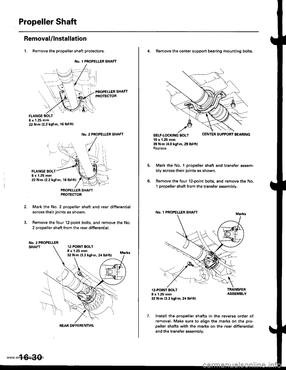
1, Remove the propeller shaft protectors.
No. 1 PROPELLER SHAFT
PROPELLER SHAFTPROTECTOR
FLANGE BOLTI x 1 .25 mm22 N.m (2.2 kg{.m. 16lbl'ft)
2.
No. 2 PROPELLER SHAFT
FLANGE BOLT8 x 1.25 mm22 N.m 12.2 kgf.m, 16lbf.ft)
PNOPELLER SHAFTPROTECTOR
Mark the No. 2 propeller shaft and rear differsntial
across their joints as shown.
Remove the four 12-point bolts. and remove the No.
2 propeller shaft from the rear differential.
No.2 PROPELLERSHAFT12.POINT BOLT8 x 1.25 mm32 N.m 13.3 kst m, 24 lbtftl
REAR DIFFERENTIAL
16-30
4, Remove the center support bearing mounting bolts.
SELF-LOCK|NG BOLT uErr rEn Durrr.r'r I I'EAnrNu
10 x 1.25 mm39 N'm 14.0 kg{.rn,29 lbtftlReplace.
Mark the No. I propeller shaft and transfer assem-
bly across their joints as shown.
Remove the four 12-point bolts, and remove the No.
1 propeller shaft from the transfer assembly,
No. 'l PROPELLER SHAFT
o.
12.POINT BOLT8 x 1.25 mm32 N.m 13.3 kgt'm, 2,1 lbf.ft)
TRANSFERASSEMBLY
7. Install the propeller shafts in the reverse order of
removal. Make sure to align the marks on the pro-
p€ller shafts with the marks on the rear differential
and the transfer assemblv.
www.emanualpro.com
Page 866 of 1395
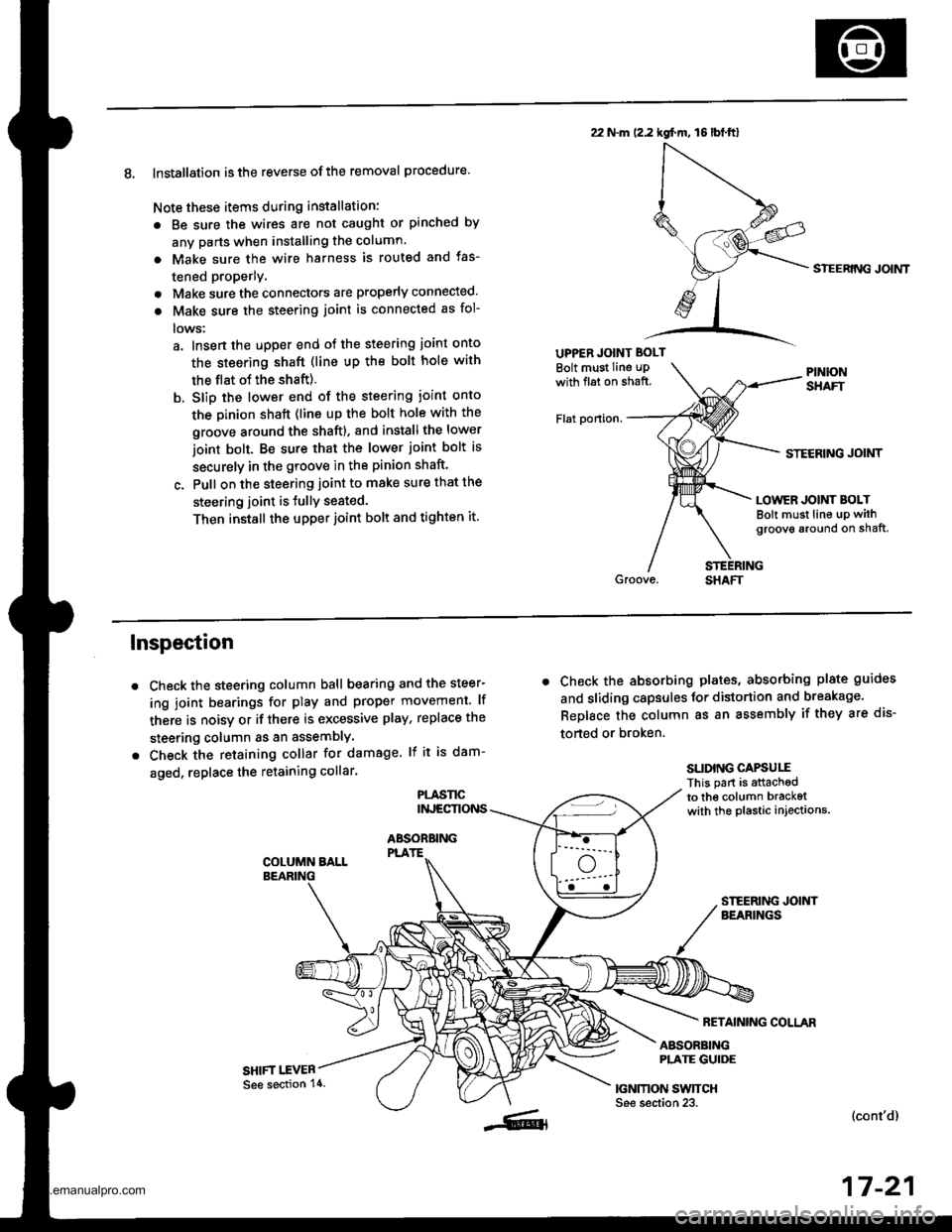
8. Installation is the reverse ofthe removal procedure.
Note these items during installation:
. Be sure the wires are not caught or pinched by
any parts when installing the column.
a Make sure the wire harness is routed and fas-
tened properly.
. Make sure the connectors are properly connected.
. Make sure the steering joint is connected as fol-
lows:
a. lnsert the uDper end of the steering joint onto
the steering shaft (line up the bolt hole with
the flat ot the shaft).
b. Slip the lower end of the steering ioint onto
the Dinion shaft (lins up the bolt hole with the
groove around the shaft). and installthe lower
ioint bolt. Be sure that the lower joint bolt is
securely in the groove in the pinion shaft'
c. Pull on the steering joint to make sure that the
steering joint is JullY seated.
Then install the upper joint bolt and tighten it.
22 N.m (2.2 kgf.m, 16lbt.ftl
UPPER JOINT BOLT
Bolt must Iine uPwith fl6t on shaft.
Flat ponion.
SIEERING JOIMT
STECRING JOINT
LOWER JOINT BOLTBolt must line up withgroove around on shaft,
Inspection
Check the steering column ball bearing and the steer-
ing joint bearings for play and proper movement. lf
there is noisy or if there is excessive play, replace the
steering column as an assemblY
Check the retaining collar for damage. lf it is dam-
aged, replace the retaining collar.
PLASl'tCINJECTIONS
ABSOBBINGPLATE
SHIFT I.EVER
. Check the absorbing plates, absorbing plate guides
and sliding capsules Jor distortion and breakage.
ReDlace the column as an assembly if they are dis-
torted or broken.
SLIDING CAPSUIIThis part is attachedto the column bracketwith the plastic injections.
FETAINING COLLAR
ABSORBINGPLATE GUIDE
|GNMON SWTTCHSee section 23.(cont'd)
17-21
See section 14.
www.emanualpro.com
Page 872 of 1395
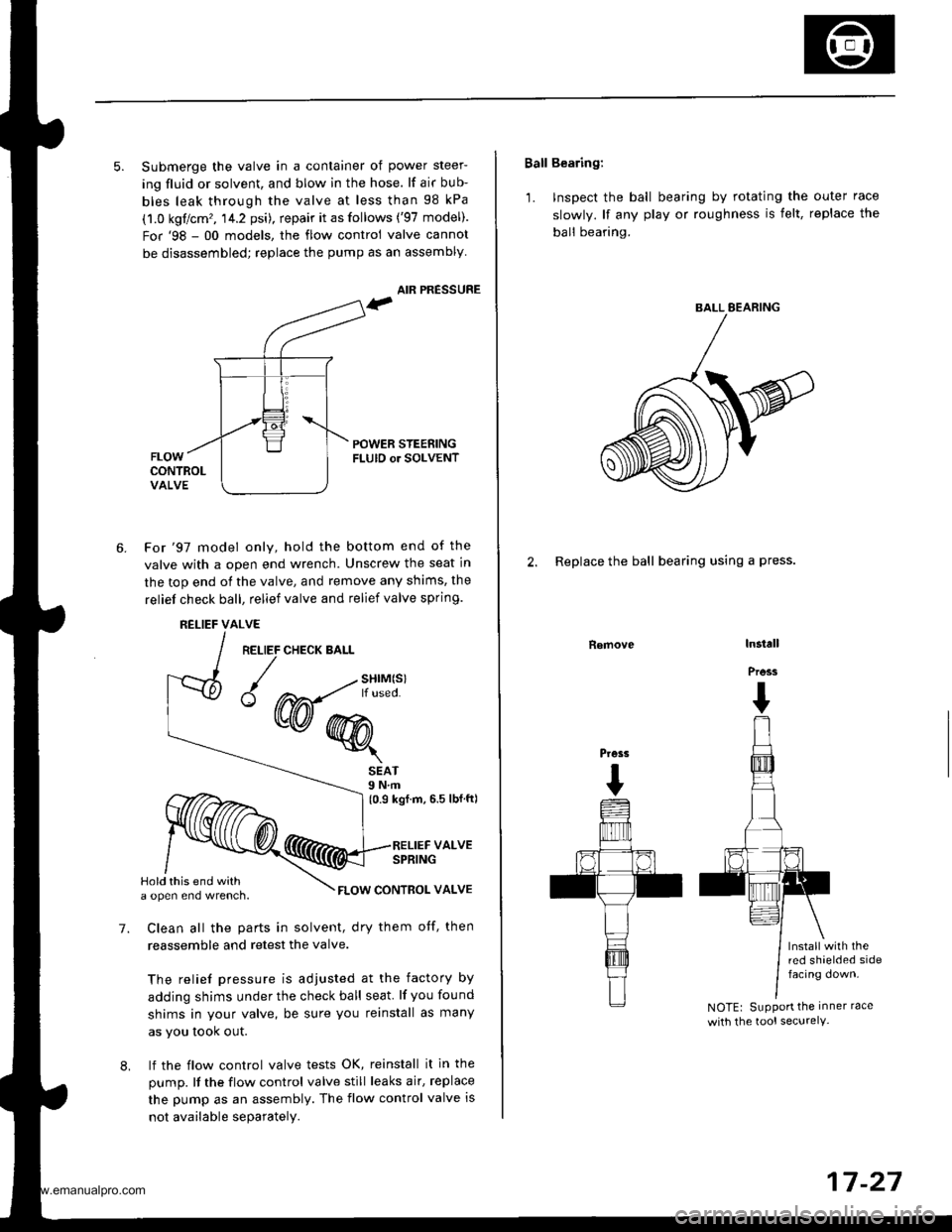
5. Submerge the valve in a container of power steer-
ing fluid or solvent, and blow in the hose. lf air bub-
bles leak through the valve at less than 98 kPa
(1.0 kgflcm'�, 14.2 psi), repair it as follows ('97 model).
For'98 - 00 models, the flow control valve cannot
be disassembled; replace the pump as an assembly
AIR PRESSURE
POWER STEENINGFLUID or SOLVENT
6.For'97 model only, hold the bottom end of the
valve with a open end wrench. Unscrew the seat in
the top end of the valve, and remove any shims, the
reliel check ball, relief valve and relief valve spring.
RELIEFALVE
RELIEF CHECK BALL
{w@r
7.
SEAT9 N.m(0.9 kgf.m, 6.5 lbfft)
RELIEF VALVESPRING
FLOW CONTBOL VALVE
Clean all the parts in solvent, dry them otf, then
reassemble and retest the valve.
The relief pressure is adjusted at the factory by
adding shims under the check ball seat lf you found
shims in your valve, be sure you reinstall as many
as you took out.
lf the flow control valve tests OK, reinstall it in the
pump. It the flow control valve still leaks air, replace
the pump as an assembly. The flow control valve is
not available separately.
8,
Hold this end witha open eno wrencn.
Ball Bearing:
'1. Inspect the ball bearing by rotating the outer race
slowly. lf any play or roughness is felt, replace the
ball bearing.
2. Replace the ball bearing using a press.
Removelnstall
Press
I
Press
I
lnstall with thered shaelded sidefacing down.
NOTEr SuPPort the inner race
with the tool securelY-
BALL EEARING
17-27
www.emanualpro.com
Page 881 of 1395
Power Steering Gearbox
Disassembly {cont'd}
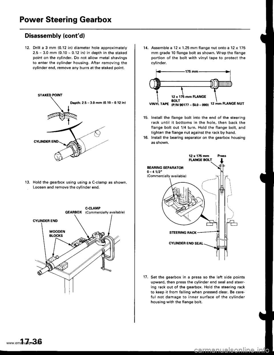
12. Drill a 3 mm (0.12 in) diameter hole approximately
2.5 - 3.0 mm (0.10 - 0.12 in) in depth in the staked
point on the cylinder. Do not allow metal shavings
to enter the cylinder housing. After removing the
cylinder end, remove any burrs at the staked point.
D.oth: 2.5 - 3.0 mm 10.10 - 0.12 inl
CYUNOER
Hold the gearbox using using a C-clamp as shown,
Loosen and remove the cvlinder end.
13.
17-36
14, Assemble a 12 x 1.25 mm flange nut onto a '12 x 175
mm grade 10 flange bolt as shown, Wrap the flange
portion of the bolt with vinyl tape to protect the
cvlinder,
VINYL TAP€ tp/N 90177 - SLO - OOOI 12mmFLANGENUT
Install the flange bolt into the end of the steering
rack until it bottoms in the hole. then back the
flange bolt out 1/4 turn. Hold the flange bolt, and
tighten the flange nut against the rack by hand.
Install the bearing separator on the gearbox housing
as snown.
15.
BEARING SEPARATOR0 - 1112'(Commercially available)
17.
STEERING RACK
CYLINDER €ND
Set the gearbox in a press so the lelt side points
upward, then press the cylinder end seal and steer-
ing rack out of the gearbox. Hold the steering rack
to keep it from falling when pressed clear. Be care-
ful not damage to inner surface of the cylinder
housing with the flange bolt.
www.emanualpro.com
Page 883 of 1395
Power Steering Gearbox
Disassembly (cont'd)
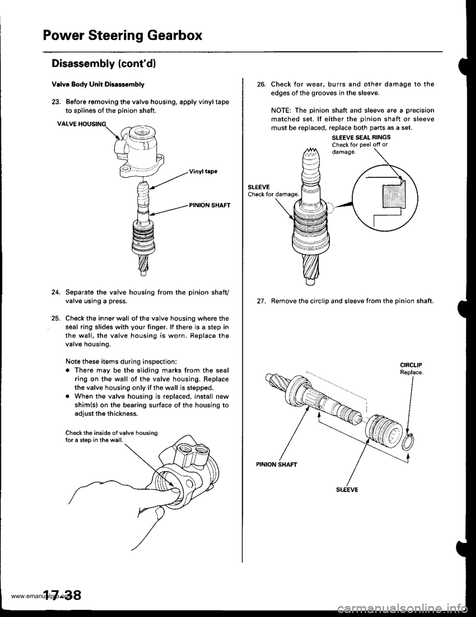
Valve Body Unit Dbassembly
23. Before removing the valve housing, apply vinyltape
to solines of the Dinion shaft.
VALVE HOUSING
Separate the valve housing from the pinion shafv
valve using a press.
Check the inner wall of the valve housing where the
seal ring slides with your finger. lf there is a step in
the wall, the valve housing is worn. Replace the
valve housing.
Note these items during inspection:
o There may be the sliding marks from the seal
ring on the wall of the valve housing. Replace
the valve housing only if the wall is stepped.
. When the valve housing is replaced, install new
shim{s) on the bearing surface of the housing to
adiust the thickness.
Check the inside ofvalve housingfor a step in the wall.
17-38
26. Check for wear, burrs and other damage to the
edges of the grooves in the sleeve.
NOTE: The pinion shaft and sleeve are a precision
matched set. lf either the oinion shaft or sleeve
must be replaced, replace both parts as a set.
SLEEVE SEAL RINGSCheck for Deel off or
27. Remove the circlip and sleeve from the pinion shaft.
www.emanualpro.com
Page 884 of 1395
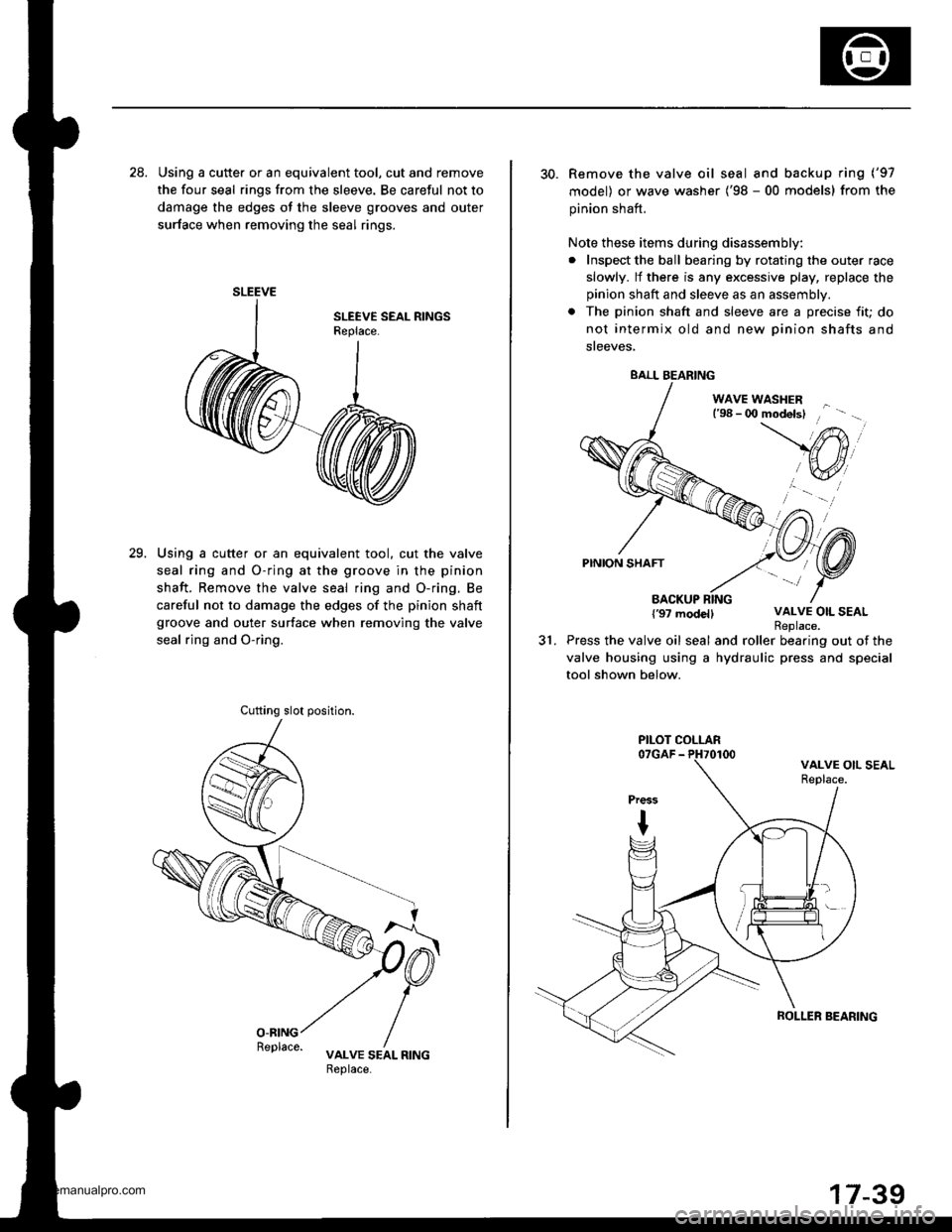
28. Using a cutte. or an equivalent tool, cut and remove
the four seal rings from the sleeve. Be careful not to
damage the edges ot the sleeve grooves and outer
surface when removing the seal rings.
Using a cutter or an equivalent tool. cut the valve
seal ring and O-ring at the groove in the pinion
shaft. Remove the valve seal ring and O-ring. Be
careful not to damage the edges of the pinion shaft
groove and outer surface when removing the valve
seal rjng and O-ring.
29.
SLEEVE
Cufting slot position.
30. Remove the valve oil seal and backup ring ('97
model) or wave washer ('98 - 00 models) from the
pinion shaft.
Note these items during disassembly:
. Inspect the ball bearing by rotating the outer race
slowly. lf there is any excessive play, replace the
pinion shaft and sleeve as an assembly.
. The pinion shaft and sleeve are a precise fit; do
not intermix old and new Dinion shafts and
sreeves,
WAVE WASHERl'98 - 0O modelsl
PINION SHAFT
BACKUP RING{'97 modellVALVE OIL SEAL
31.Replace.Press the valve oil seal and roller bearing out of the
valve housing using a hydraulic press and special
tool shown below.
BALL BEARING
PILOT COLLAR
ROLLER SEARING
www.emanualpro.com
Page 885 of 1395
Power Steering Gearbox
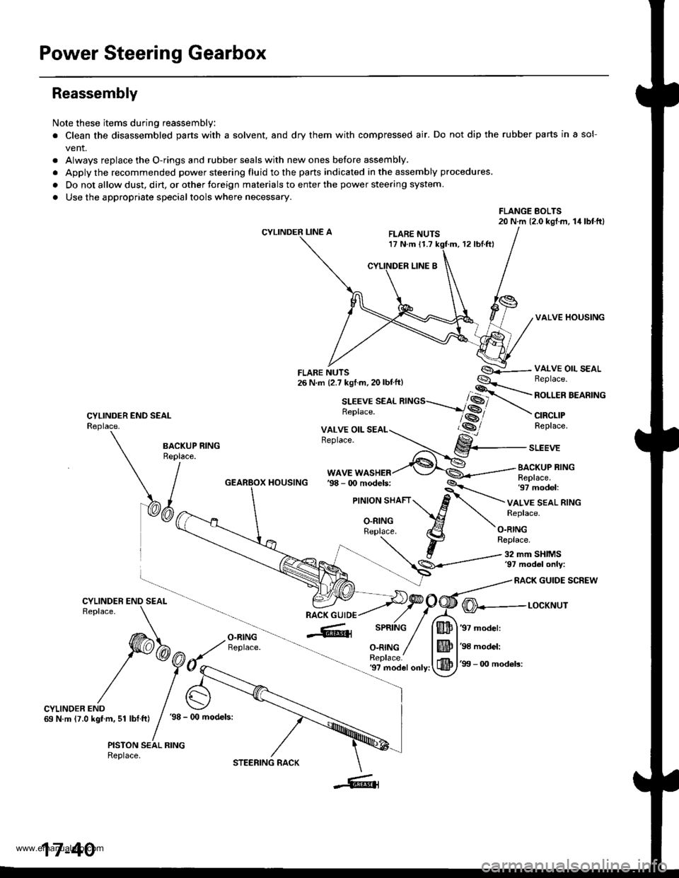
Reassembly
Note these items during reassembly
. Clean the disassembled parts with a solvent, and dry them with compressed air. Do not dip the rubber parts in a sol-
vent.
. Always replace the O-rings and rubber seals with new ones before assembly.
. Apply the recommended power steering fluid to the parts indicated in the assembly procedures.
. Do not allow dust. dirt, or other toreign materials to enter the power steering system.
. Use the appropriate specialtools where necessary.
FLANGE BOLTS20 N.m (2.0 kgl.m, 14lbtftl
CYLINDER LINE AFLARE NUTS17 N.m 11.712 rbl.ftl
VALVE HOUSING
CYLINDER END SEALReplace.
VALVE OIL SEALBeplace.
ROLLER BEARING
CIRCLIPReplace.
BA.KUP RING
\/^"
WAVE WASHERBACKUP RINGReplace.97 model:HOUSING
VALVE SEAL RINGReplace.
O.RINGReplace.
32 mm SHIMS'97 mod6l only:
RACK GUIDE SCREW
O-RINGReplace.
@---r-ocxr'rur
'97 model:
'98 model:
'99 - 0O mod6ls:'9? model only:
CYLINDER END69 N.m (7.0 kgf.m, 51 lbf.ft)'98 - (x) models:
PISTON SEAL RINGReplace.
17-40
STEERING RACK
www.emanualpro.com
Page 886 of 1395
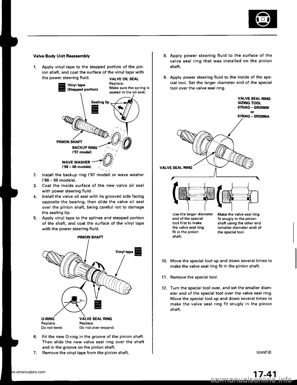
Valve Body Unh Roa$embly
1. Apply vinyl tape to the stepped portion of the pin-
ion shaft, and coat the surface of the vinyl tape with
the power steering fluid.
Vinyl tape(Stopp6d portion)
VALVE OIL SEALReplace.Make sure the spring isseated in the oil seal.
Serling
E
7.
PINION SHAFT
BACKUP RING137 modell
WAVE WASHER{'98 - 00 modelsl
Install the backup ring {'97 model) or wave washer
('98 - 00 models).
Coat the inside surface of the new valve oil seal
with power steering fluid.
Install the valve oil seal with its grooved side facing
opposite the bearing, then slide the valve oil seal
over the pinion shaft, being careful not to damage
the sealing lip.
Apply vinyl tape to the splines and stepped ponion
of the shaft, and coat the surface of the vinyl tape
with the power steering fluid.
Vinyl trp€
O.RINGReplace.Do not twist.R€place-Do not over-expand.
Fit the new O-ring in the groove of the pinion shaft.
Then slide the new valve seal ring over the shaft
and in the groove on the pinion shaft,
Remove the vinyl tape from the pinion shaft.
\/
PINION SHAFT
8.Apply power steering fluid to the surface of the
valve seal ring that was installed on the pinion
shaft.
Apply power steering fluid to the inside of the spe-
cial tool. Set the larger diameter end of the special
tool over the valve seal ring.
VALVE SEAL RINGSIZNG TOOL07NAG - SR309q'ot07NAG - SR3oltoA
Mak€ the valve seal ringfit snugly in the pinion
shatt using th6 other end{smaller diameter end) otthe special tool.
10.
11.
12.
Move the special tool up and down several times to
make the valve seal ring fit in the pinion shaft,
Remove the soecial tool.
Turn the special tool over, and set the smaller diam-
eter end of the specisl tool over the valve seal ring.
Move the special tool up and down several times to
make the valve seal ring fit snugly in the pinion
shaft.
(cont'd)
lrr.rj1
tffifrE-rr.]
r\-''] 7
Usg th6 larg€r diameterend of the specialtoollirst to maketh€ valve seal ringtit in the pinion
shaft.
17-41
www.emanualpro.com
Page 888 of 1395
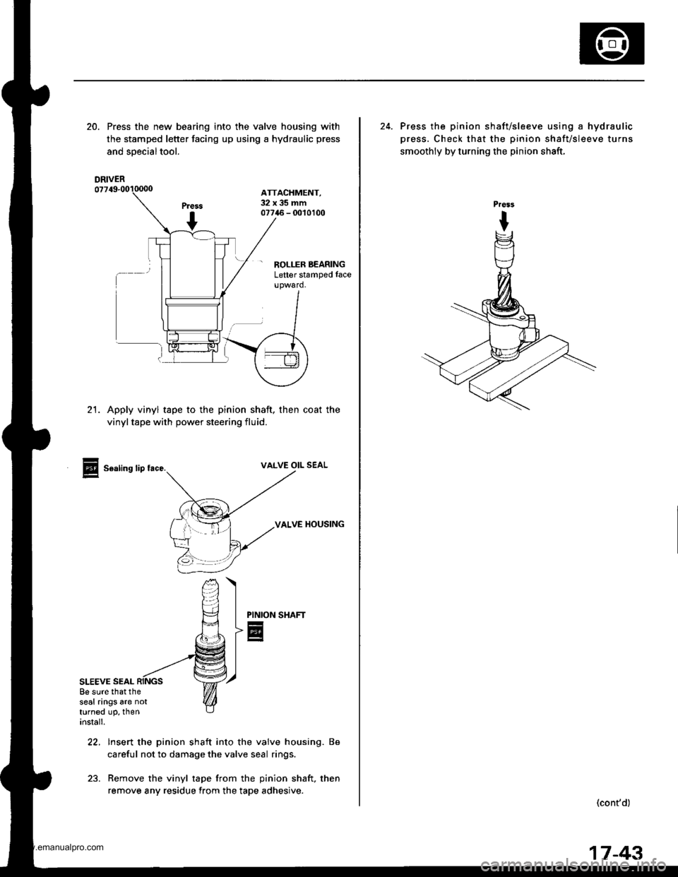
20. Press the new bearing into the valve housing with
the stamped letter facing up using a hydraulic press
and soecialtool.
ATTACHMENT,32x35mm07746 - 0010100
- ROLLER BEARINGLetter stamped face
21. Apply vinyl tape to the pinion shaft, then coat the
vinyltape with power steering fluid.
Sealing lip tace.VALVE OIL SEAL
VALVE HOUSING
SHAFT
SLEEVE SEAL
PINION
E
22, Insert the pinion shaft into the valve housing. Be
careful not to damage the valve seal rings.
23. Remove the vinyl tape from the pinion shaft, then
remove any residue from the tape adhesive.
8e sure that theseal rings are notturned up, theninstall.
DRIVER
24. Press the pinion shaft/sleeve using a hydraulic
press. Check that the pinion shaft/sleeve turns
smoothly by turning the pinion shaft,
(cont'd)
17-43
www.emanualpro.com