Bearing HONDA CR-V 2000 RD1-RD3 / 1.G Workshop Manual
[x] Cancel search | Manufacturer: HONDA, Model Year: 2000, Model line: CR-V, Model: HONDA CR-V 2000 RD1-RD3 / 1.GPages: 1395, PDF Size: 35.62 MB
Page 941 of 1395

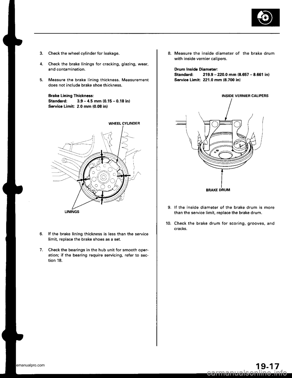
Check the wheel cylinder for leakage.
Check the brake linings for cracking, glazing, wear,
and contamination.
Measure the brake lining thickness. Measurement
does not include brako shoe thickness.
Brake Lining Thicknoss:
Standard: 3.9 -,1.5 mm {0.15 - 0.18 inl
Sorvice Limil: 2.0 mm {0.08 in}
lf the brake lining thickness is less than the service
limit, replace the brake shoes as a set.
Check the bearings in the hub unit for smooth oper-
ation; if the bearing require servicing. refer to sec-
tion 18.
7.
WHEEL CYLINOER
LININGS
8. Measure the inside diameter of the brake drum
with inside vernier calioers,
Drum Insido Diamoter:
Standard: 219.9 - 220.0 mm (8.657 - 8.661 in)
Service Limit: 221.0 mm {8.700 inl
lf the inside diameter of the brake drum is more
than the service limit, replaca the brake drum.
Check the brake drum for scoring, grooves, and
cracKs.
10.
BRAKE DRUM
19-17
www.emanualpro.com
Page 981 of 1395

Pulsers/Wheel Sensors
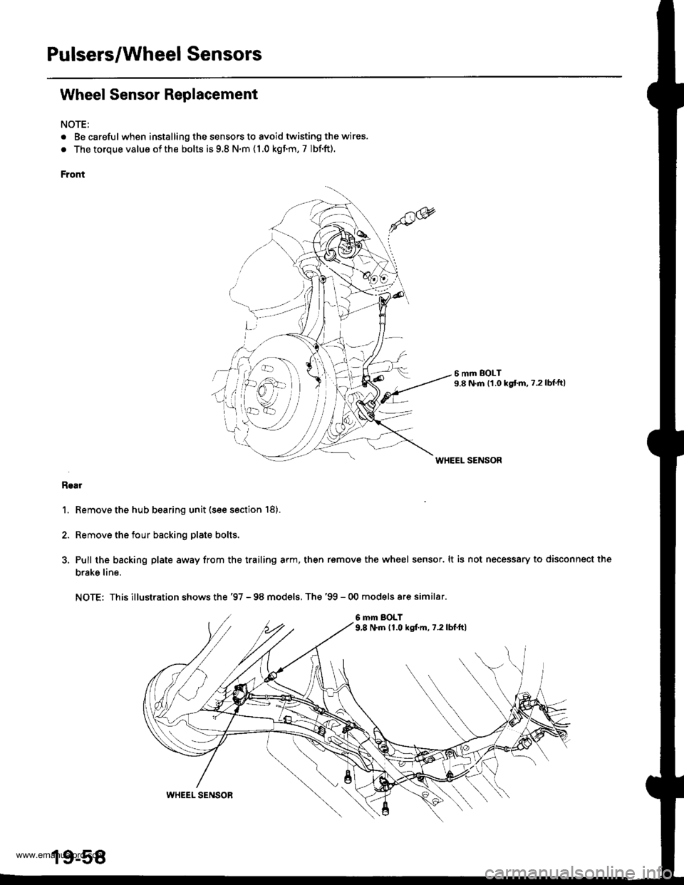
Wheel Sensor Replacement
NOTE;
. Be carefulwhen installing the sensors to avoid twisting the wires.
. The torque value of the bolts is 9.8 N.m ( 1.0 kgf.m, 7 Ibf.ft).
Front
6 mm BOLT9.8 N.m {1.0 kgtm. ?.2lbf'ft)
WHEEL SENSOR
Rgar
1. Remove the hub bearing unit (see section 18).
2. Remove the tour backing plate bolts.
3, Pull the backing plate away from the trailing arm, then remove the wheel sensor. lt is not necessary to disconnect the
brake line.
NOTE: This illustration shows the '97 - 98 models, The '99 - 00 models are similar.
6 mm BOLT9,8 N.m 11.0 kgf.m, 7.2lbf.ft)
\all
19-58
WHEEL SENSOR
www.emanualpro.com
Page 1153 of 1395

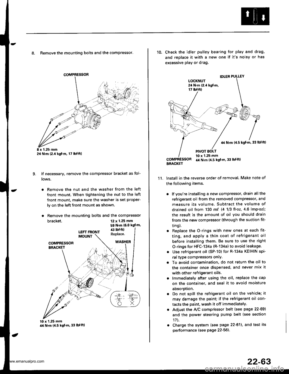
8. Remove the mounting bolts and the compressor.
E x 1.25 mm2a N.m (2.,1kgf.m, l7 lbl.ft)
lf necessary, remove the compressor bracket as fol-
lows.
. Remove the nut and the washer from the left
front mount. When tightening the nut to the left
front mount, make sure the washer is set proper-
ly on the left front mount as shown.
. Remove the mounting bolts and the compressor
bracket.
q
12 x 1.25 mm
59 N.m (6.0 kgt'm,
10 x 1,25 mmart N.m (4.5 kgf'm, 33 lbfftl
11.
10. Check the idler pulley bearing for play and drag,
and replace it with a new one if it's noisy or has
excessive play or drag.
lnstall in the reverse order of removal. Make note of
the following items,
. lf you're installing a new compressor, drain all the
reJrigerant oil from the removed compressor, and
measure its volume. Subtract the volume of
drained oil trom 130 m/ 14 U3 fl'o2,4.6 lmp'oz);
the result is the amount of oil you should drain
lrom the new compressor (through the suction fit-
trngl.
. Replace the O-rings with new ones at each fit-
ting, and apply a thin coat o{ refrigerant oil
before installing them. Be sure to use the right
O-rings for HFC-134a (R-134a) to avoid leakage.
. Use refrigerant oil (SP-10) for R-134a KEIHIN spi-
ral type compressors only.
. To avoid contamination, do not return the oil to
the container once dispensed, and never mix it
with other refrigerant oils.
. lmmediately after using the oil, replace the cap
on the container. and seal it to avoid moisture
aDsorprlon.
. Do not spill the refrigerant oil on the vehicle; it
may damage the paint; if the retrigerant oil con-
tacts the Daint, wash it off immediately.
. Adjust the Ay'C compr'essor b€lt (see psge 22-69)
and the power steering pump belt {see section
17t.
. Charge the system (see page 22-611, and test its
performance (see page 22-56]-.
IDLER PULLEY
+r N.m 14.5 kgt m,33lbf ftl
PIVOT BOLT10 x 1.25 mmir4 N.m {4.5 kgt m, 33 lbl'ft}BBACKET
www.emanualpro.com
Page 1155 of 1395

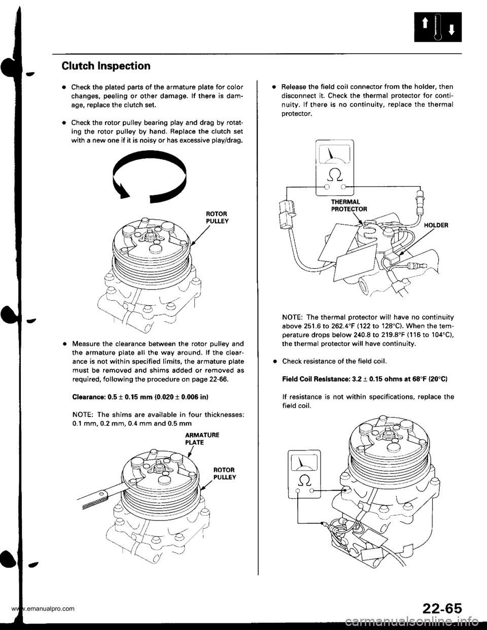
Clutch Inspection
Check the plated parts of the armature plate for color
changes, peeling or other damage. lf there is dam-
age, replace the clutch set.
Check the rotor pulley bearing play and drag by rotat-
ing the rotor pulley by hand. Replace the clutch set
with a new one if it is noisy or has excessive play/drag.
Measure the clearance between the rotor pulley and
the armature plate all the way around. lf the clear-
ance is not within specified limits, the armature plate
must be removed and shims added or removed as
required, following the procedure on page 22-66.
Cloarance: 0.5 t 0.15 mm {0.020 t 0.q)6 in)
NOTE: The shims are available in four thicknesses:
0.1 mm. 0.2 mm. 0.4 mm and 0.5 mm
ABMATUBE
ROTOR
. Release the field coil connector from the holder, then
disconnect it. Check the thermal protector for conti-
nuity, lf there is no continuity, replace the thermal
prorecror.
NOTE: The thermal protector will have no continuity
above 251.6 to 262.4"F 1122 to 128"C). When the tem-perature drops below 240.8 to 219.8"F (116 to 104'C),
the thermal protector will have continuity.
Check resistance of the field coil.
Field Coil Resistance: 3.2 i 0.15 ohms at 68"F {20'C)
lf resistance is not within specifications, replace the
field coil.
22-65
www.emanualpro.com