Start HONDA CR-V 2000 RD1-RD3 / 1.G Workshop Manual
[x] Cancel search | Manufacturer: HONDA, Model Year: 2000, Model line: CR-V, Model: HONDA CR-V 2000 RD1-RD3 / 1.GPages: 1395, PDF Size: 35.62 MB
Page 680 of 1395
Transfer
4.
Inspection
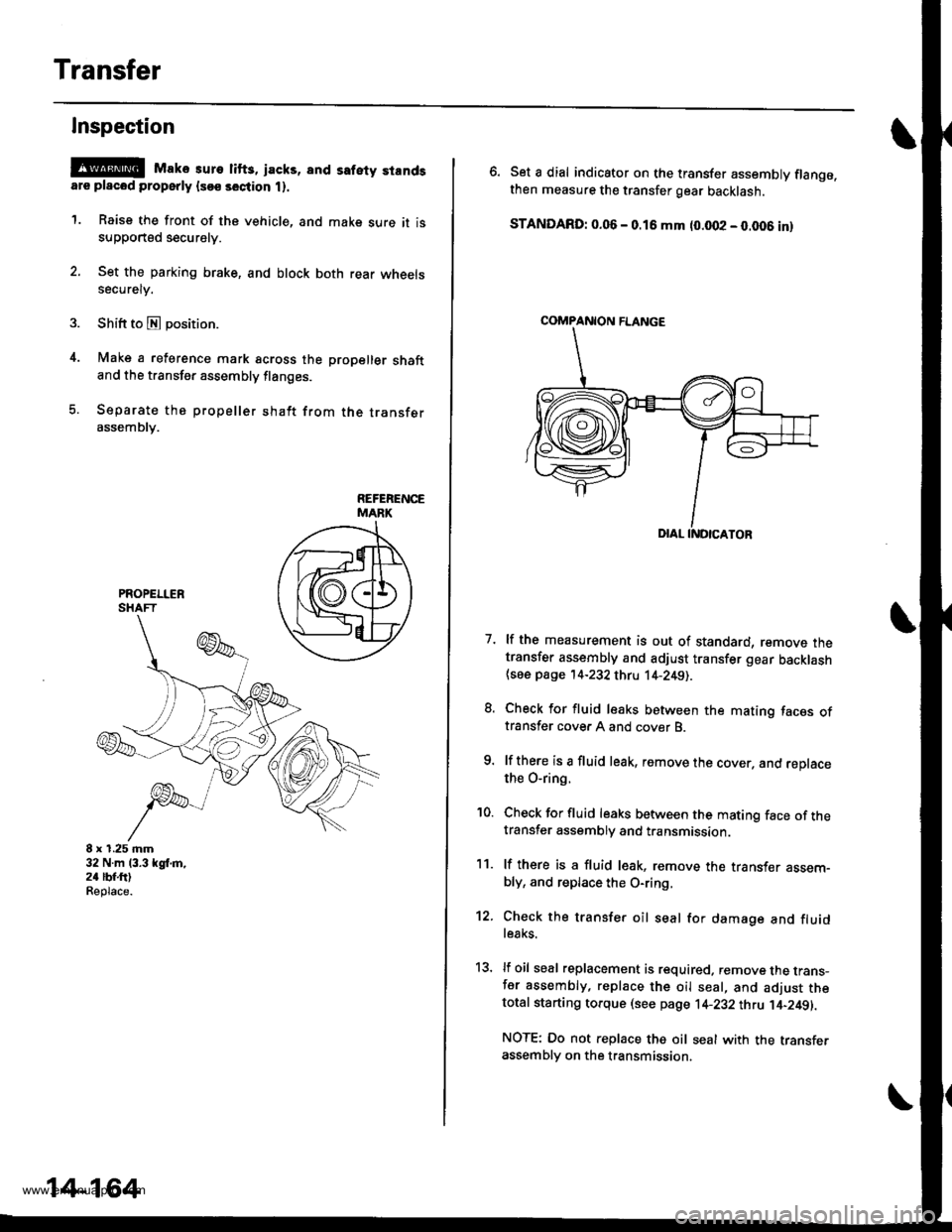
@E Mako suro lifts, jacks, and safety standsare placod properly lsoe section t).
1. Raise the front of the vehicle, and make sure it issupported securely.
2. Set the parking brake, and block both rear wheelssecurely.
Shift to E position.
Make a reference mark across the propeller shaftand the transfer assembly flanges.
Separate the propeller shaft from the transferassembly.
8 x 1.25 mm32 N.m 13.3 kgl,m,24 lbf.ftlReplace.
14-164
\
6. Set a dial indicator on the transfer assembly flange.then measure the transfer gear backlash.
STANDARD: 0.06 - 0.16 mm (0.002 - 0.006 inl
7. lf the measurement is out of standard, remove thetransfer assembly and adjust transfer gear backlash{see page '14-232 thru 14-2491.
8. Check for fluid leaks between the mating faces oftransfer cover A and cover B.
9. lf there is a fluid leak, remove the cover, and reDlacethe O-ring.
'10. Check for fluid leaks between the mating face of thetransfer assembly and transmission.
11. lf there is a fluid l€ak, remove the transf€r assem-bly, and replace the O-ring,
12. Check the transfer oil seal for damage and fluidle8ks.
13, lf oil seal replacement is required. remove the trans-fer assembly, replace the oil seal, and adjust thetotal starting torque (see page 1+232 thtu ]'4-249||.
NOTE: Do not replace the oil seal with the transferassembly on the transmission.
COMPANION FLANGE
www.emanualpro.com
Page 684 of 1395
Transfer Assembly
Installation (cont'dl
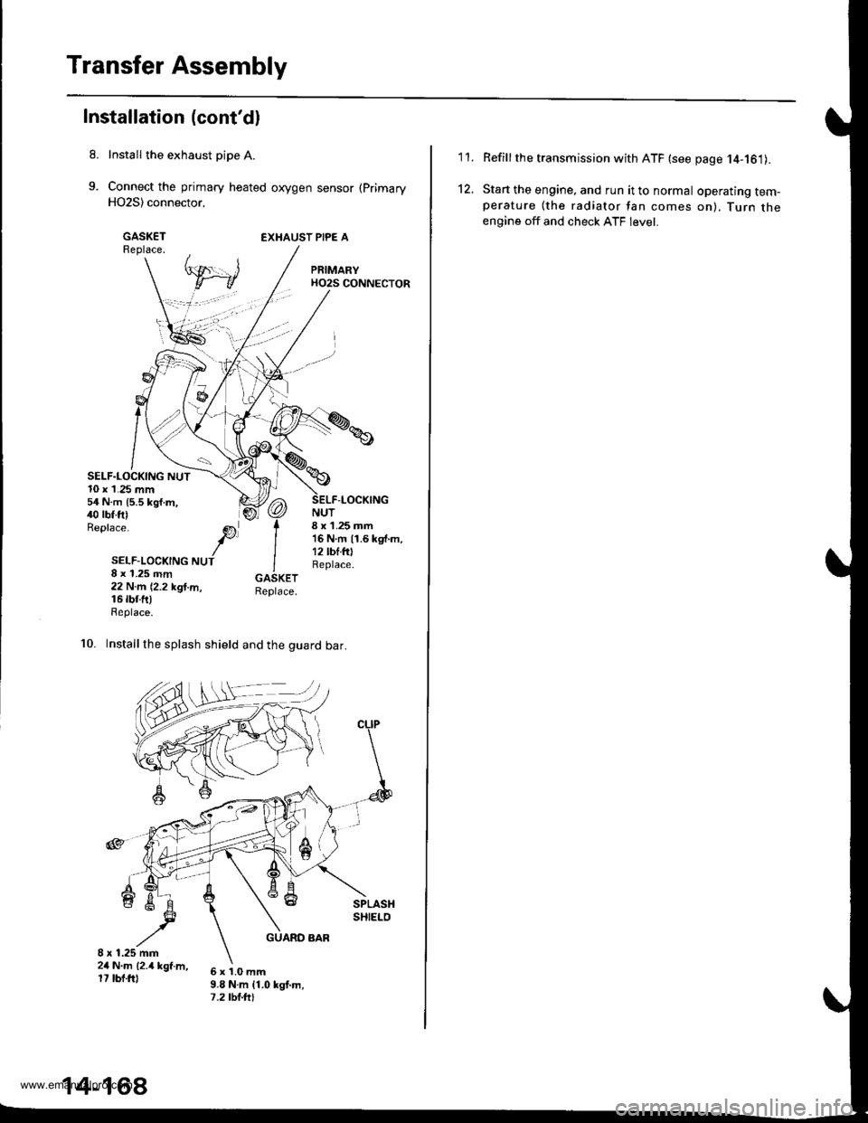
Install the exhaust pipe A.
Connect the primary heated oxygen sensor (Primary
H02S) connector,
GASKETReplace.EXHAUST PIPE A
SELF.LOCKING NUT10 x 1.25 mm54 N.m {5.5 kgf.m,40 rbf.ft)Replace.
NUT8 x 1.25 mm16Nm11.6kgf.m,12 lbf.fOReplace.
-LOCKING
SELF-LOCKING NUT8 x 1.25 mm22 N.m (2.2 kgl.m,16 rbr.fttReplace.
10. Installthe splash shield and the guard bar.
6x1.0mm9.8 N.m {1.0 kgt.m,7.2 tbt.ftt
14-168
'I '�I.
12.
Refillthe transmission with ATF (see page 14-161).
Start the engine, and run it to normal operating tem-perature (the radiator fan comes on), Turn theengine off and check ATF level.
www.emanualpro.com
Page 685 of 1395

Transmission
Removal
@
2.
'1.
Make sure lifts. iacks, and safety stands aro placed
properly, and hoist brackets are attached to the col-
rest position on the engine lsee section 11.
Apply th€ parking brake and block the r€ar wheels,
so vehicls will noi roll off the stands and fall on you
while working under it.
NOTE: Use fender covers to avoid damaging painted
surfaces.
Disconnect the negative terminal, then disconnect
the positive terminal from the battery.
Remove the intake air duct and the air cleaner hous-
ing assembly,
Remove the starter cables. Remove the harness
clamp from the clamp bracket.
5.
STARTERCABLES
Remove the transmission ground cable terminal
and the radiator hose clamp lrom the transmission
hanger.
Disconnect the lock-up control solenoid valve con-
nector, then remove the harness clamp from the
clamp bracket.HARNESS CLAMP
RADIATOR HOSECLAMP
CONTROLSOLENOID VALVECONNECTOR
CLAMP
6. Disconnect the vehicle speed sensor (VSS), the coun-
tershaft speed sensor, and the A/T gear position
switch connectors.
A/T GEAR POSITIONSWITCH CONNECTOR
VEHICLE SPEEDSENSOR |VSS'
CONNECTORBfiACKET
SPEED SENSORCONNECTOR
7. Remove the transmission housing mounting bolts.
MOUNTING BOLTS
(cont'd)
14-169
www.emanualpro.com
Page 689 of 1395
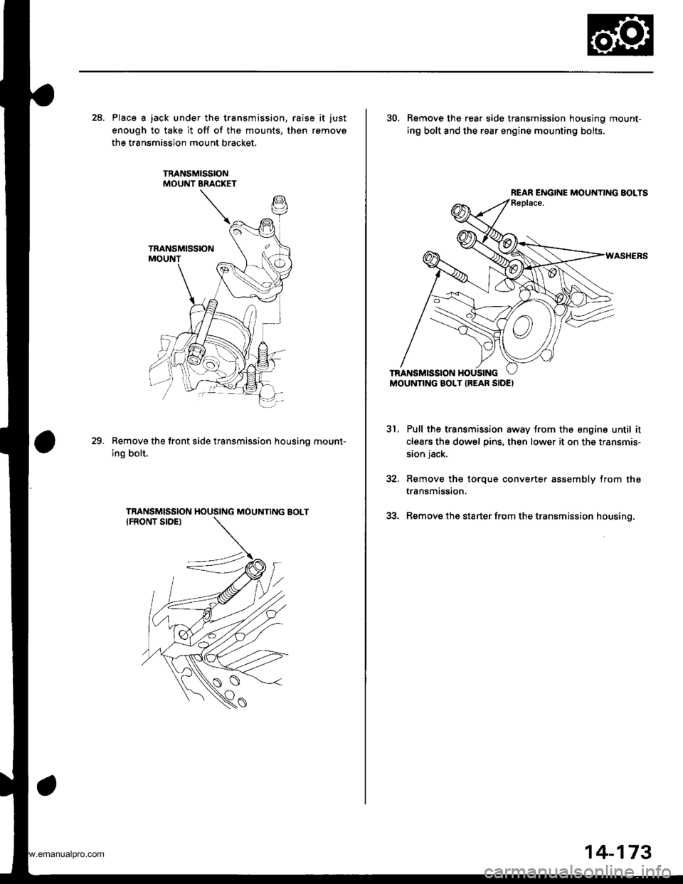
28. Place a jack under the transmission, raise it just
enough to take it off of the mounts, then remove
the transmission mount bracket.
Remove the front side transmission housino mount-
ing bolt.
29.
30. R€move the rear side transmission housing mount-
ing bolt and the rear engine mounting bolts.
Pull the transmission away from the engine until it
clears the dowel pins, then lower it on the transmis-
sion jack.
Remove thg torque converter assembly from the
transmission.
Remove the starter from the transmission housing.
31.
REAR ENGINE MOUNTING BOLTS
14-173
www.emanualpro.com
Page 736 of 1395
Clutch
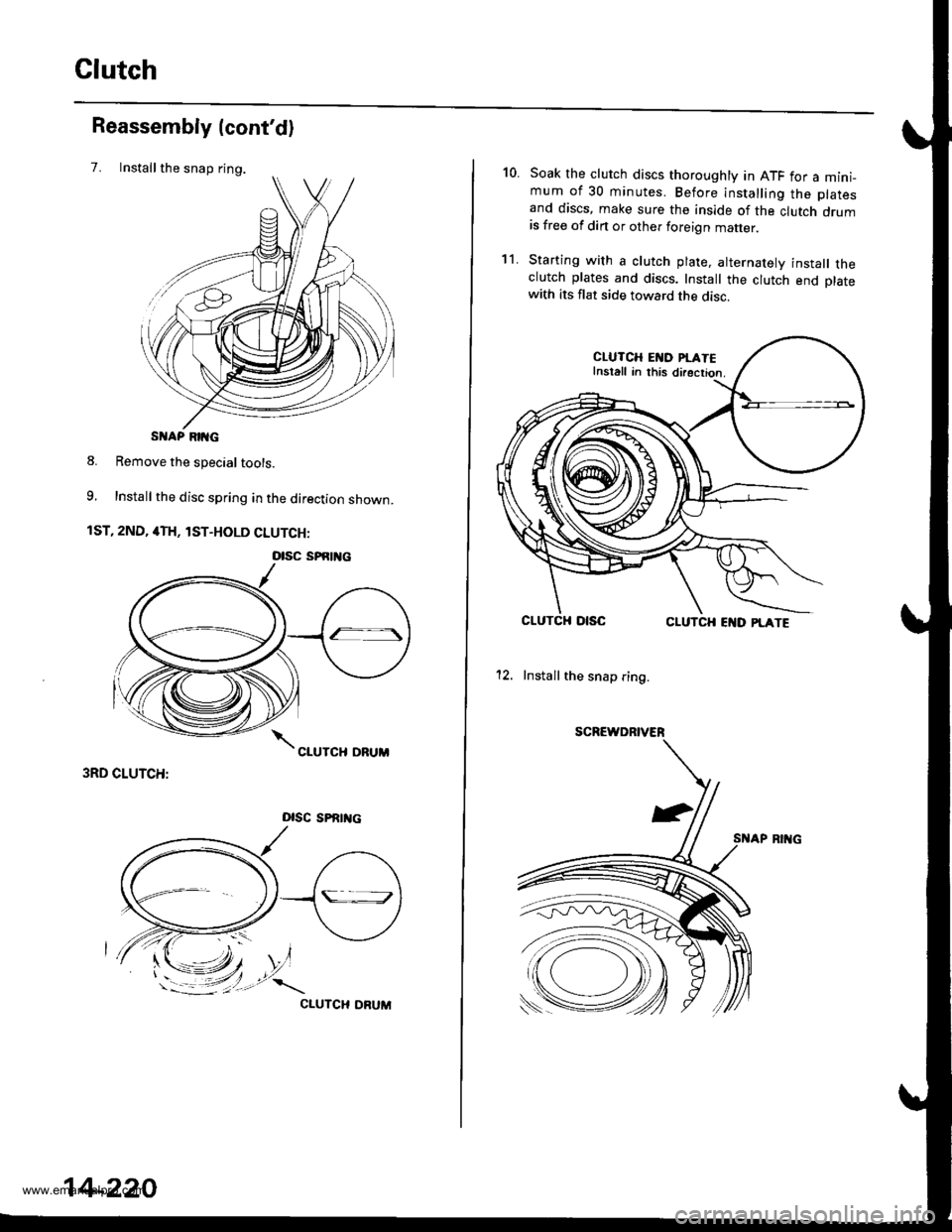
Installthe snap ring.
Reassembly (cont'd)
7.
S AP RIIG
8. Remove the special tools.
9, Install the disc spring in the direction shown.
1ST, 2ND, 4TH, lST-HOLD CLUTCH:
3RD CLUTCH:
Dlsc sPRrrtc
CIUTCH ORUM
otsc sPfitl{c
14-220
10.Soak the clutch discs thoroughly in ATF for a mini_mum of 30 minutes. Before installing the platesand discs, make sure the inside of the clutch drumis free of din or other foreign matter
Starting with a clutch plate, alternatelv install theclutch plates and discs. Install the clutch end platewith its flat side toward the disc.
CLUTCH EI{D PI.ATEInstall in this directior.
CLUTCHCLUTCH EI{D PLATE
12. Install the snap ring.
SCREWDRIVER
't1.
www.emanualpro.com
Page 749 of 1395
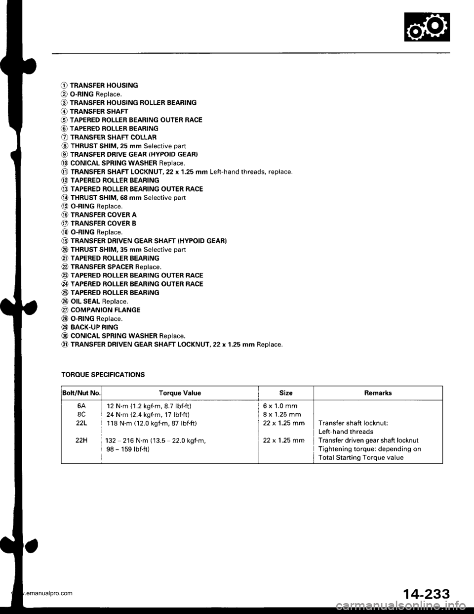
O TRANSFER HOUSING
O o-RING Replace.
O TRANSFER HOUSING ROLLER BEARING
@ TRANSFER SHAFT
O TAPERED ROLLER BEARING OUTER RACE
@ TAPERED ROLLER BEARING
O TRANSFER SHAFT COLLAR
@ THRUST SHIM, 25 mm Selective part
€) TRANSFER DRtvE GEAR (HYPoID GEAR}
@ coNtcAL SPRtNG WASHER Reptace,
@ TRANSFER SHAFT LOCKNUT,22 x 1.25 mm Left-hand rhreads, replace.
(D TAPERED ROLLER EEARING
@ TAPERED ROLLER EEARING OUTER RACE(} THRUST SHIM, 68 mm Selective part
@ O-RING Replace.
@ TRANSFER coVER A
(} TRANSFER COVER B
@ o-RING Replace.
(9 TRANSFER DRIVEN GEAR SHAFT (HYPOID GEAR)
@ THRUST SHIM, 35 mm Selective part
@ TAPERED ROLLER BEARING
@ TRANSFER SPACER Reptace.
@ TAPERED RoLLER BEARTNG OUTER RACE
@ TAPERED ROLLER BEARING OUTER RACE
@ TAPERED BOLLER BEARTNG
@ olL SEAL Replace.
@ COMPANION FLANGE
@ o-RING Replace.
@ BACK-UP RING
@ coNtcAL SPRtNG WASHER Reptace.
@ TRANSFER DRIVEN GEAR SHAFT LOCKNUT,22 x 1.25 mm Replace.
TOROUE SPECIFICATIONS
Boh/Nut No.Torque ValueSizeRemarks
6A
8C
22L
22H
12 N'm (1.2 kgf.m,8.7 lbf.ft)
24 N.m (2.4 kgf.m, 17 lbnft)
118 N.m (12.0 kgim,87 Ibift)
132 216 N.m (13.5 22.0 kgf.m,
98 - 159 lbift)
6x1.0mm
8 x 1.25 mm
22 x 'l.25 mm
22 x 1.25 mm
Transfer shaft locknut:
Left hand threads
Transfer driven gear shaft locknut
Tightening torque: depending on
Total Starting Torque value
14-233
www.emanualpro.com
Page 750 of 1395
Transfer Assembly
Inspection
NOTE: To prevent damage to the transfer housing,
always use soft jaws or equivalent materials between
the transfer housing and the vise.
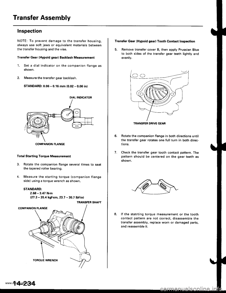
Trsnsfer Gear (Hypoid gear) Backl8sh M€asurem€nt
1. Set a dial indicator on the companion flange as
snown.
2. Measure the transfer gear backlash.
STANDARD: 0.06 - 0.16 mm {0.02 - 0.06 in)
Total Starting Torque Meagurgm€nt
3, Rotate the companion flange several times to seat
the tapered roller bearing.
4. Measure the starting torque (companion flange
side) using a torque wrench as shown,
STANDARD:
2.68 - 3.,17 N.m(27.3 - 35.,1 kgf.cm, 23.7 - 30.7 lbf.inl
TRANSFER SHAFT
DIAL INDICATOR
COMPANION FLANGE
14-234
Transfer Gear (Hypoid gear) Tooth Contact Inspection
5, Remove transfer cover B, then apply Prussian Blue
to both sides of the transfer gear teeth lightly and
Rotate the companion flange in both directions until
the transfer gear rotates one full turn in both direc-
tions.
Check the transfer gear tooth contact pattern. Thepattern should be centered on the gear tseth as
snown.
6.
7.
8.lf the statrting torque measurement or the tooth
contact pattern are not correct, disassemble the
transfer assembly, replace worn or damaged parts,
and reassemble it.
TRANSFER DRIVE G€AR
www.emanualpro.com
Page 756 of 1395
Transfer Assembly
Reassembly
NOTE:
. While reassembling the transfer assembly:. Check and adjust the transfer gear tooth contact.. Measure and adjust the transfer gear backlash.. Check and adjust the tapered roller bearing stan-
ing torque.
. Coat all pans with ATF during reassembly.. Replace the tapered roller bearing and the bearing
outer race as a set if either part is replaced.. Replace the transfer drive gear and the transfer dri-ven gear shaft as a set if either part is replaced.
Outline of Assembly
1.Select the 35 mm thrusi shim.
Psrtorm this procedute if the transter driven g€ar
shaft or the tapered roller bearing on the transfer
driven gear shaft is replaced.
Prea$emble the parts to check and adiust transtelgear backlash and transfer gear tooth contact.
Disassemble the parts, then assemble the translerdriven gsar shaft and its related pans.
2.
3.
4. Measure and adjust the starting torque oI the
transfer driven gear shaft tapered roller bearing.
5. Assemble the transfer shaft and its related parts.
6. Measure and adiust the total starting torque.
35 mm Thrust Shim Selection
L Select the 35 mm thrust shim if the transfer drivengear shaft or the tapered roller bearing on the trans-
fer driven gear shaft is replaced.
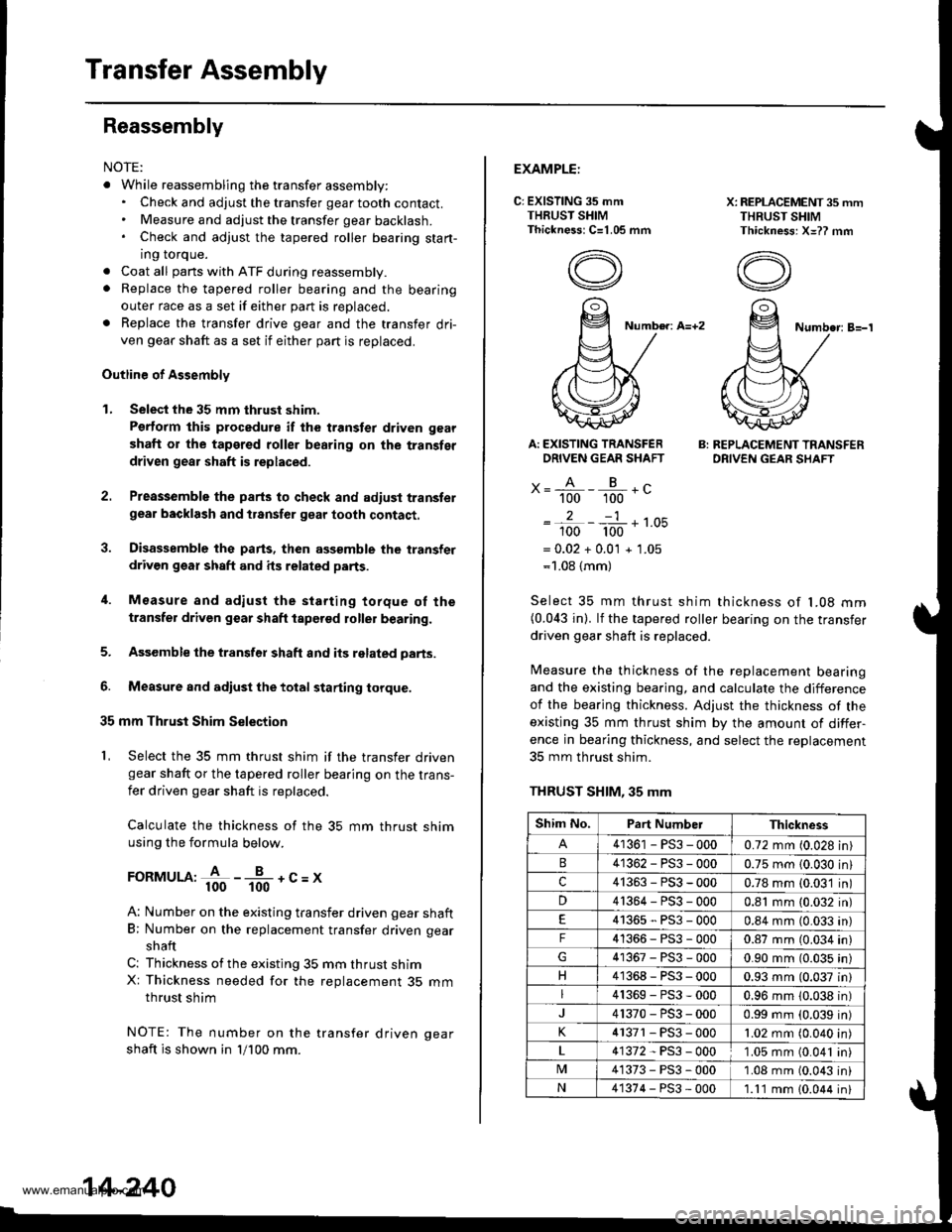
Calculate the thickness of the 35 mm thrust shimusing the formula below.
FoRMULA:+ -*-+c=x
A: Number on the existing transfer driven gear shaft
B; Number on the replacement transfer driven gear
shaft
C: Thickness ofthe existing 35 mm thrust shimX: Thickness needed for the replacement 35 mmthrust shim
NOTE: The number on the transfer driven oear
shaft is shown in 'll100 mm.
14-240
EXAMPLE:
C: EXISTING 35 mmTHRUST SHIMThickness: C=1.05 mm
X: REPLACEMENT 35 mmTHRUST SHIMThickness: X=?? mm
Number: A=+2Numbe.: B=-'l
Ar EXISTING TRANSFERDRIVEN GEAR SHAFT
x= A - B .c" 100 100 -
2-1
100 100 '-
= 0.02 + 0.0'l + 1.05=1.08 {mm)
B: REPLACEMENT TRANSFERDRIVEN GEAR SHAFT
Select 35 mm thrust shim thickness of l�08 mm(0.043 in). lf the tapered roller bearing on the transfer
driven gear shaft is replaced.
Measure the thickness of the replacement bearingand the existing bearing, and calculate the difference
of the bearjng thickness. Adjust the thickness of the
existing 35 mm thrust shim by the amount of differ-
ence in bearing thickness, and select the replacement
35 mm thrust shim.
THRUST SHIM, 35 mm
Shim No.Part NumberThickness
41361 - PS3 - 0000.72 mm (0.028 in)
41362-PS3-0000.75 mm {0.030 in}
c41363-PS3-0000.78 mm (0.03'1 in)
D41364-PS3-0000.81 mm (0.032 in)
41365-PS3-0000.84 mm (0.033 an)
F41366-PS3-0000.87 mm (0.034 in)
41367-PS3-0000.90 mm (0.035 in)
H41368-PS3-0000.93 mm (0.037 in)
41369-PS3-0000.96 mm 10.038 in)
41370-PS3-0000.99 mm (0.039 in)
K4 r371 - PS3 - 0001.02 mm (0.040 in
41372-PS3-0001.05 mm (0.041 in
M41373-PS3-0001.08 mm (0.043 in
N41374-PS3-000'1.11 mm 10.044 in
www.emanualpro.com
Page 758 of 1395
Transfer Assembly
Reassembly (cont'd)
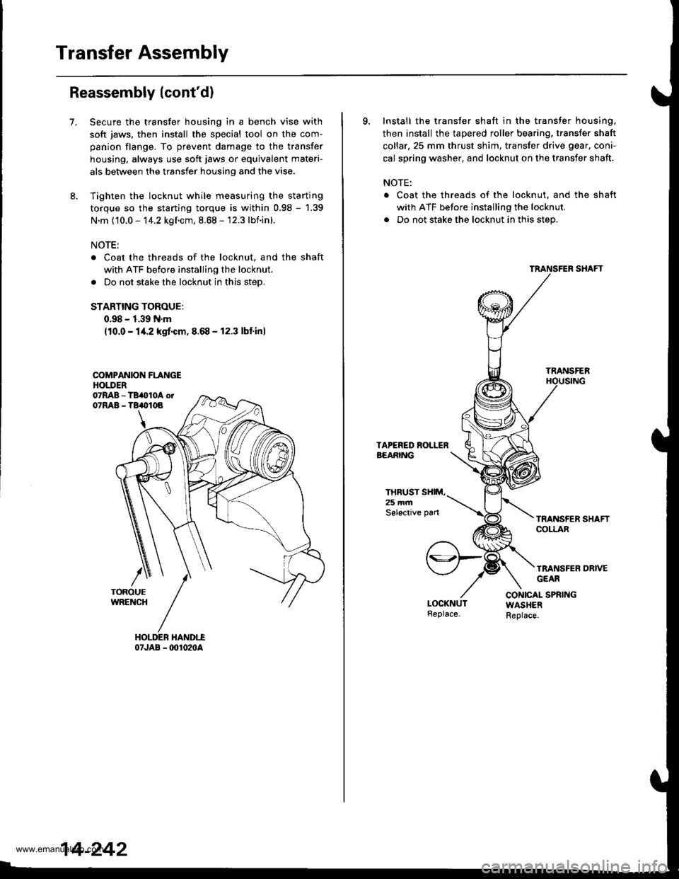
7.Secure the transfer housing in a bench vise with
soft jaws, then install the special tool on the com-
panion flange. To prevent damage to the transfer
housing, always use soft jaws or equivalent materi-
als between the transfer housing and the vise.
Tighten the locknut while measuring the starting
torque so the starting torque is within 0.98 - '1.39
N.m (10.0 - 14.2 kgf.cm, 8.68 - 12.3 lbnin).
NOTE:
Coat the threads of the locknut, and the shaft
with ATF before installing the locknut.
Do not stake the locknut in this step.
STARTING TOROUE:
0.98 - 1.39 N.m
{10.0 - 14.2 kgrf.cm,8.68 - 12.3 lbf'inl
COMPANION FLANGEHOLDER
07JAB - @1020A
14-242
9. Install the transfer shaft in the transfer housing,
then install the tapered roller bearing, transfer shaft
collar.25 mm thrust shim, transfer drive gear, coni-
cal spring washer, and locknut on the transfer shaft.
NOTE:
. Coat the threads of the locknut. and the shaft
with ATF before installing the locknut.
. Do not stake the locknut in this step.
TRANSFER
THRUST SXIM,25 mmSelective pan
TRANSFER DRIVEGEAR
CONICAL SPRINGWASHERReplace.
www.emanualpro.com
Page 761 of 1395
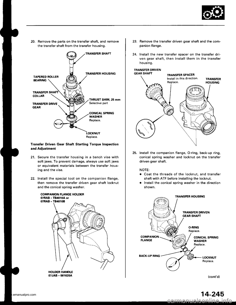
20. Remove the parts on the transfer shaft, and remove
the transfer shaft from the transfer housinq.
TRANSFER SHAFT
TRANSFER HOUSINGTAPEFED ROLLERBEARNG
TRANSFERCOLLAR
TRANSFER DRIVEGEAR
THRUST SHIM, 25 mmSelective pan
CONICAL SPRINGWASHERReplace.
Transf€r Driven Gear Shaft Starting Torque Inspsction
and Adjustment
21. Secure the transfer housing in a bench vise with
soft jaws, To prevent damage, always use soft jaws
or equivalent materials between the transfer hous-
ing and the vise.
22. Install the special tool on the companion flange,
then remove the transfer driven oear shaft locknut
and the conical spring washer.
COMPANION FLANGE HOLDER07RAB - TB,010A ol07RAB - TB,010B
Replace.
23. Remove the transter driven gear shaft and the com-
panion flange,
24. Install the new transfer spacer on the transfer dri-
ven gear shaft, then install them in the transfer
housrng.
TRANSFER DRIVENGEAR SHAFTTFANSFER SPACERlnstall in this direction.Replace.
25.Install the companion flange, O-ring, back-up ring.
conical spring washer and locknut on the transfer
driven gear shaft.
NOTE:
. Coat the threads of the locknut, and transfer
shaft with ATF before installing the locknut.
. Install the conical spring washer in the direction
shown,
TRANSFER HOUSING
O.RINGReplace.
CONICAL SPRINGWASHERReplace.
LOCKNUTReplace.
(cont'd)
BACK.UP RING
14-245
www.emanualpro.com