Clearance HONDA CR-V 2000 RD1-RD3 / 1.G User Guide
[x] Cancel search | Manufacturer: HONDA, Model Year: 2000, Model line: CR-V, Model: HONDA CR-V 2000 RD1-RD3 / 1.GPages: 1395, PDF Size: 35.62 MB
Page 117 of 1395
Valve Clearancev
Adjustment (cont'dl
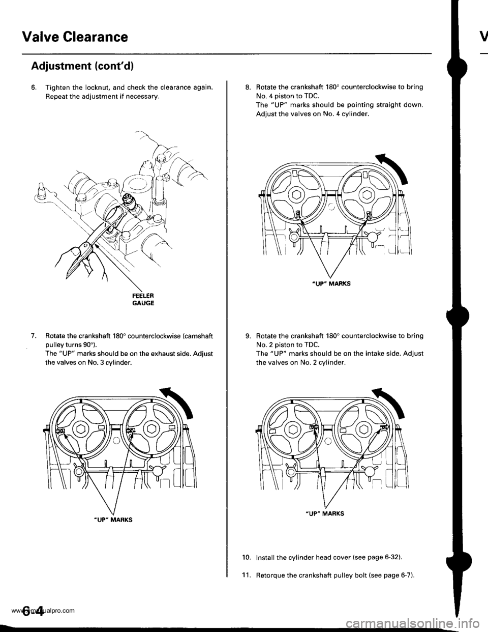
6. Tighten the locknut, and check the clearance agajn.
Repeat the adjustment if necessary.
GAUGE
Rotate the crankshaft 180" counterclockwise (camshaft
pulley turns 90').
The "UP" marks should be on the exhaust side. Adjust
the valves on No. 3 cylinder.
.UP" MARKS
7.
8. Rotate the crankshaft 180" counterclockwise to brinq
No. 4 piston to TDC.
The "UP" marks should be pointing straight down.
Adjust the valves on No. 4 cylinder.
Rotate the crankshaft 180'counterclockwise to brino
No.2 piston to TDC.
The "UP" marks should be on the intake side. Adiust
the valves on No. 2 cylinder.
Install the cylinder head cover (see page 6-32).
Retorque the crankshaft pulley bolt (see page 6-7).
10.
11.
"UP" MARKS
"UP" MARKS
www.emanualpro.com
Page 135 of 1395
Camshafts
4.
Inspection
1.
7.
Loosen the adjusting screws.
Remove the camshaft holders.
Mark the rocker arms, then remove them.
Reinstall the camshaft and holders. Tighten the
camshaft holder bolts in a crisscross pattern, begin-
ning with the inner bolts.
9.8 N.m (1.0 kgf.m.7.2 lbf.ft)
Seat the camshafts by pushing them toward the dis-
tributor end of the head with a screwdriver.
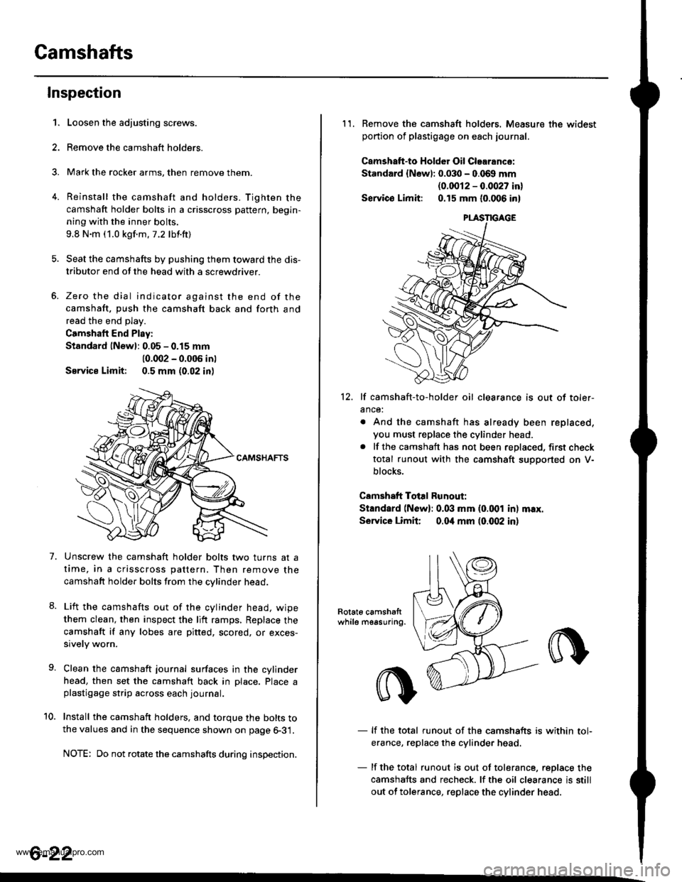
Zero the dial indicator against the end of the
camshaft, push the camshaft back and forth and
read the end play.
Camshaft End Play:
Standard lNewl: 0.05 - 0.15 mm
10.002 - 0.005 in)
Service Limit: 0.5 mm (0.02 in)
Unscrew the camshaft holder bolts two turns at a
time, in a crisscross pattern, Then remove the
camshaft holder bolts from the cvlinder head.
Lift the camshafts out of the cylinder head. wipe
them clean, then inspect the lift ramps, Replace the
camshaft if any lobes are pitted, scored, or exces-
sively worn.
Clean the camshaft journal surfaces in the cylinder
head, then set the camshaft back in Dlace. Place aplastigage strip across each journal.
Install the camshaft holders. and torque the bolts tothe values and in the sequence shown on page 6-31.
NOTE: Do not rotate the camshafts during inspection.
8.
10.
6-22
11. Remove the camshaft holders. Measure the widest
portion of plastigage on each journal.
Camshatt-to HoldGr Oil Clearance:
Standard {Newl: 0.030 - 0.069 mm
{0.0012 - 0.0027 in}
Servico Limit: 0.15 mm (0.006 in)
12. lf camshaft-to-holder oil clearance is out of toler-
ance:
. And the camshaft has already been replaced,
you must replace the cylinder head.. lf the camshaft has not been replaced, first check
total runout with the camshaft suoDorted on V-
blocks.
Camshaft Total Runout:
Standard (N6w): 0.03 mm (0.001 in) max.
Service Limit 0.04 mm (0.(X)2 in)
Rotat6 camshattwhile measuring.
- lf the total runout of the camshafts is within tol-
erance, replace the cylinder head
- lf the total runout is out of tolerance, replace the
camshafts and recheck. lf the oil clearance is still
out of tolerance, replace the cylinder head.
www.emanualpro.com
Page 138 of 1395
Valve Guides
Valve Movement
1. Measure the guide-to-stem clearance with a dial
indicator while rocking the stem in the direction of
normal thrust (wobble method),
lntake Valve Stem-to-Guide Clearance:
Standard (Newl: 0.04 - 0.10 mm
(0.002 - 0.004 in)
Service Limit 0.16 mm (0.006 in)
Exhaust Valve Stem-to-Guide Clearance:
Standard {Newl: 0.10 - 0.16 mm
(0.004 - 0.006 inl
Service Limit: 0,22 mm (0.009 inl
lf the measurement exceeds the service limit,
recheck using a new valve.
lf the measurement is now within the service limit,
reassemble using a new valve.
lf the measurement still exceeds the limit, subtract the
O.D. of the valve stem, measured with a micrometer,
from the l.D. of the valve guide, measured with an
inside micrometer or ball gauge.
Take the measurements in three places along the
valve stem and three places inside the valve guide
The difference between the largest guide measure-
ment and the smallest stem measurement should
not exceed the service limit.
lntake Valve Stem-to-Guide Clearance:
Standard (New): 0.02 - 0.05 mm
{0.001 - 0.002 in)
Service Limit: 0.08 mm (0.003 in)
Exhaust Valve Stem-to-Guide Clearance:
Standard (New): 0.05 - 0.08 mm
(0.002 - 0.003 in)
Service Limit: 0.11 mm (0.004 in)
2.
3.
Replacement
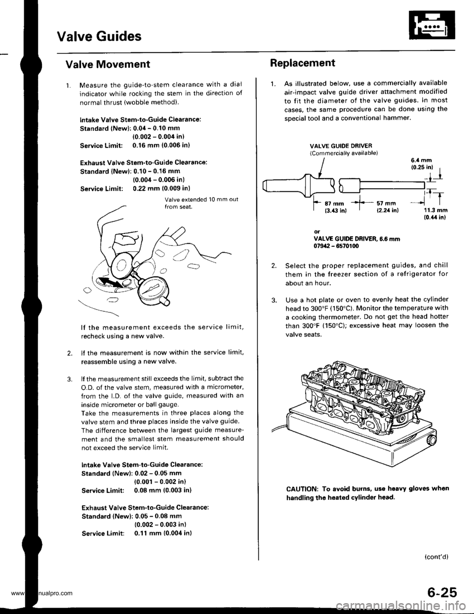
1. As illustrated below, use a commercially available
air-impact valve guide driver attachment modified
to fit the diameter of the valve guides. In most
cases, the same procedure can be done using the
sDecial tool and a conventional hammer.
VALVE GUIDE DRIVER(Commerciallv available)
2.
3.
(0.25 inl I
_,1-r
,_T-_lrl
'11.3 mm(0.{,r in}
orVALVE GUIDE DRIVER, 6.6 mm0t9a:I - G5t01q)
Select the proper replacement guides. and chill
them in the freezer section of a refrigerator for
about an hour.
Use a hot plate or oven to evenly heat the cylinder
head to 300"F (150"C). Monitor the temperature with
a cooking thermometer. Do not get the head hofter
than 300'F (150"C); excessive heat may loosen the
valve seaIs.
6.4 mm
CAUTION: To avoid burns, uss heavy gloves when
handling the heated cylinder head.
(cont'd)
6-25
*]-- sz mm' l2.21inl
www.emanualpro.com
Page 140 of 1395
Cylinder Head
Reaming
NOTE: For new valve guides only.
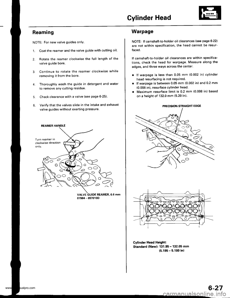
1. Coat the reamer and the valve guide with cutting oil.
2. Rotate the reamer clockwise the full length of the
valve guide bore.
Continue to rotate the reamer clockwise while
removing it from the bore.
Thoroughly wash the guide in detergent and water
to remove anY cutting residue.
Check clearance with a valve (see page 6-25).
Verify that the valves slide in the intake and exhaust
valve guides without exerting pressure.
3.
4.
5.
6.
vALvE GUIDE REAMER,6.6 mm0798i1 - 657010O
REAMER HANDLE
e
Warpage
NOTE: lf camshaft-to-holder oil clearances (see page G22)
are not within specification, the head cannot be resur-
faced.
lf camshaft-to-holder oil clearances are within specifica-
tions, check the head for warpage. Measure along the
edges, and three ways across the center.
. if warpage is less than 0.05 mm (0.002 in) cylinder
head resurfacing is not required
lf warpage is between 0.05 mm (0.002 in) and 0.2 mm
(0.008 in), resurface cylinder head.
Maximum resurface limit is 0.2 mm (0.008 in) based
on a height of 132.0 mm (5.20 in).
Cylind€r Hesd Height:
Standard {New}: 131.95 - 132.05 mm
15.195 - 5.199 inl
PRECISION STRAIGHT EDGE
6-27
www.emanualpro.com
Page 145 of 1395

Cylinder Head
Installation (cont'dl
'13. Align the marks on the cylinder head plug to thecylinder head upper surface, then install the cylin
der head plug in the end of the cylinder head.
CYLINOER HEADPLUGReplace.
lnstallthe back cover.
To set the camshafts at TDC position for the No. lpiston, align the holes in the camshafts with theholes in the No. l camshaft holders and insert 5.0mm pin punches in the holes. Install the keys into
the camshaft grooves.
37 N m (3.8 *gl.m, 27 lbt.tr)
9.8 N.m (1.0 kgtm,7.2|hrftl
Push the camshaft pulleys onto the camshafts. thentighten the retaining bolts to the torque specified.
6-32
14.
KEYS
I x 1.25 mm
6x1.0mm
Install the timing belt (see page 6-1 1).
Adjust the valve clearance (see page 6-3).
Thoroughly clean the head cover gasket and thegroove.
lnstall the head cover gasket in the groove of thecylinder head cover. Seat the head cover gasket in
the recesses for the camshaft first, then work it into
the groove around the outside edges. Make sure thehead cover gasket is seated securely in the corners
of the recesses with no gap.
17.
'18.
19.
www.emanualpro.com
Page 147 of 1395
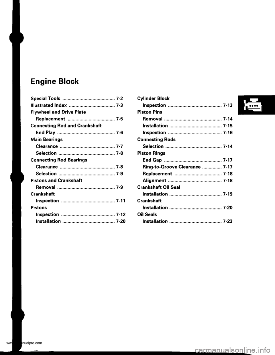
Engine Block
Speciaf Tools .............7-2
lllustrated lndex ................................... 7-3
Flywheel and Drive Plate
Replacement ..,.,....7-5
Connecting Rod and Grankshaft
End Play .................7-6
Main Bearings
Cfearance ...............7 -7
Selection ................7-8
Connecting Rod Bearings
Clearance ...............7-8
Selection ................7-9
Pistons and Crankshaft
Removal .................7-9
Crankshaft
Inspection .............. 7-11
Pistons
fnspection ..............7-12
fnstaflation .............7-20
Cylinder Block
Inspection ..............7-13
Piston Pins
Removal ..,.......,,..... 7-14
Installation ............. 7-15
Inspection .............. 7-16
Connecting Rods
Selection ................7 -14
Piston Rings
End Gap .................7 -17
Ring-to-Groove Clearance ............... 7 -17
Replacement .........7-18
Alignment .............. 7-18
Crankshaft Oil Seal
lnstallation ............. 7-19
Crankshaft
lnstalfation .............7-20
Oil Seals
fnstalfation ....,..,.....7-23
www.emanualpro.com
Page 150 of 1395
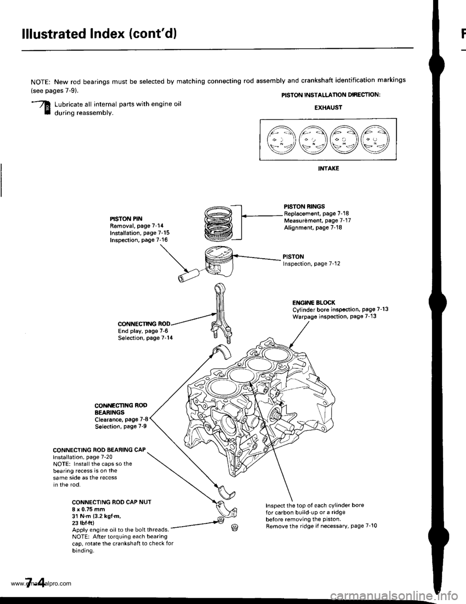
lllustrated Index (cont'd)
NOTE: New rod bearings
(see pages 7-91.
must be selected by matching connecting rod assembly and crankshaft identification markings
PISTON INSTALLANON DIRECTION:
Lubricate all internal parts with engine oil
during reassembly.EXHAUST
INTAKE
PISTON RINGSReplacement. page 7-18Measurdment, page 7-17Alignm€nt, page 7-18
PISTONInspection, page 7-12
l1\AAtr\
\9q9Q9e/
PISTON PINRemoval, page 7-14
Installation, page 7-15Inspection. page 7-16
ENGINC BLOCKCylinder bore inspection. pago 7-13
Warpage inspoction, Page 7-'13
CONNECTING ROD BEARING CAPlnstallation, page 7-20NOTE: Install the caps so thebearing recess is on thesame side as the recessin the rod.
CONNECTING ROD CAP8 x 0.75 mm31 N.m {3.2 kgl.m.23 tbf.ftl
CONNECTING
COiINECI'ING RODBEARINGSClearance, page 7-8
Solection. page 7-9
NUT
End play, page 7-6Selection, page 7-14
Inspect the top ot each cylinder borefor carbon build up or a ridgebelore removing the piston.
Remove the ridge if necessary, page 7-10Apply engine oil to the bolt threads.NOTE: After torquing each bearingcap, rotate the crankshaft to check forbinding.
7-4
www.emanualpro.com
Page 153 of 1395
Main Bearings
2.
3.
1.
4.
Clearance
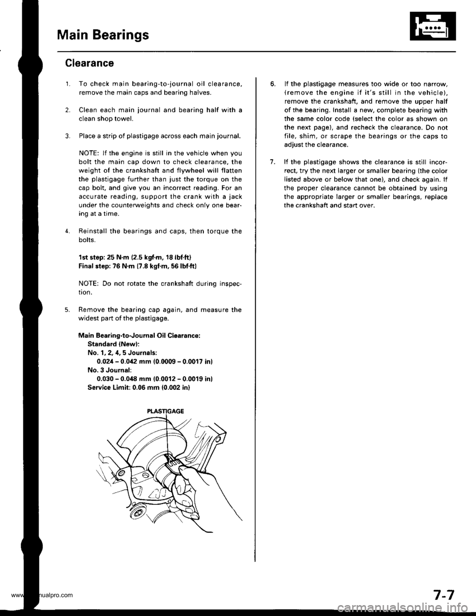
To check main bearing-to-journal oil clearance,
remove the main caps and bearing halves.
Clean each main journal and bearing half with a
clean shop towel.
Place a strip of plastigage across each main journal.
NOTE: lf the engine is still in the vehicle when you
bolt the main cap down to check clearance, the
weight of the crankshaft and flywheel will flatten
the plastigage further than just the torque on the
cap bolt, and give you an incorrect reading. For an
accurale reading, support the crank with a jack
under the counterweights and check only one bear-
Ing aI a Irme.
Reinstall the bearings and caps, then torque the
bolts,
1st step:25 N'm (2.5 kgf.m, 18lbf.ft)
Final siep: 76 N'm 17.8 kgl.m, 56 lbf.ftl
NOTE: Do not rotate the crankshaft during inspec-
tron.
Remove the bearing cap again, and measure the
widest part of the plastigage.
Main Bearing.to.Journal Oil Clearance:
Stand8.d {New):
No. 1,2,4,5 Journsls:
0.02i1- 0.0i12 mm (0.0009 - 0.0017 inl
No. 3 Journal:
0.030 - 0.0i18 mm (0.0012 - 0.0019 inl
Service Limit: 0.06 mm 10.002 in)
lf the plastigage measures too wide or too narrow,(remove the engine if it's still in the vehicle),
remove the crankshaft, and remove the upper half
of the bearing. Install a new, complete bearing with
the same color code (select the color as shown on
the next page). and recheck the clearance, Do not
file, shim, or scrape the bearings or the caps to
adjust the clearance.
lf the plastjgage shows the clearance is still incor-
rect, try the ne)d larger or smaller bearing {the color
listed above or below that one), and check again. lf
the proper clearance cannot be obtained by using
the appropriate larger or smaller bearings, replace
the crankshaft and start over.
7.
7-7
www.emanualpro.com
Page 154 of 1395
Main BearingsConnecting Rod Bearings
Selection
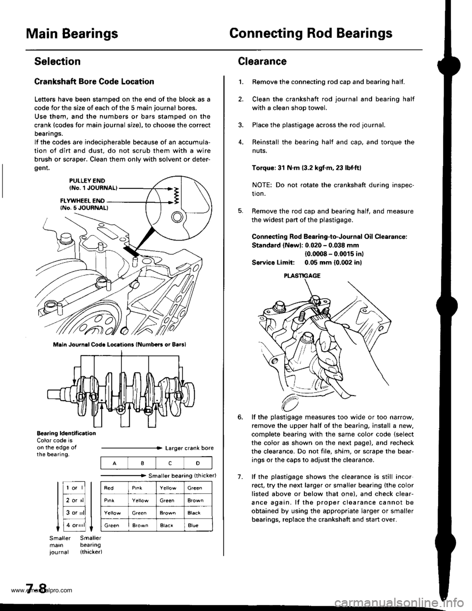
Crankshaft Bore Code Location
Letters have been stamDed on the end of the block as a
code Jor the size of each of the 5 main journal bores.
Use them, and the numbers or bars stamped on the
crank (codes for main journal size), to choose the correct
beanngs.
lf the codes are indecipherable because of an accumula-
tion of dirt and dust. do not scrub them with a wire
brush or sc.aper. Clean them only with solvent or deter-
gent.
Main Journ.l Cod. Locrtions lNumbcB oi Bar3l
Bearing ld.ntif icrtionColor code ison the edge ofthe bearing.
7-8
IcD
"""""""" Smallerbearing(rhicker)
Green
Green
ElaclAlue
Clearance
Remove the connecting rod cap and bearing half.
Clean the crankshaft rod journal and bearing half
with a clean shop towel.
Place the plastigage across the rod journal.
Reinstall the bearing half and cap, and torque the
nuts.
1.
7.
Torqus: 31 N.m (3.2 kgf.m. 23 lbf.ft)
NOTE: Do not rotate the crankshaft during inspec-
tion.
Remove the rod cap and bearing half, and measure
the widest part of the plastigage.
Connesting Rod Bearing-to-Journal Oil Clearancc:
Standard {Newl: 0.020 - 0.038 mm
{0.0008 - 0.0015 in)
Service Limit: 0.05 mm {0.002 inl
lf the plastigage measures too wide or too narrow,
remove the upper half of the bearing, install a new.
complete bearing with the same color code {select
the color as shown on the next page), and recheck
the clearance. Do not file, shim, or sc.ape the bear-
ings or the caps to adjust the clearance.
lf the plastigage shows the clearance is still incor
rect, try the next larger or smaller bearing {the color
listed above or below that one). and check clear-
ance again. lf the proper clearance cannot be
obtained by using the appropriate larger or smaller
bearings. replace the crankshaft and start over.
PLASTIGAGE
www.emanualpro.com
Page 158 of 1395
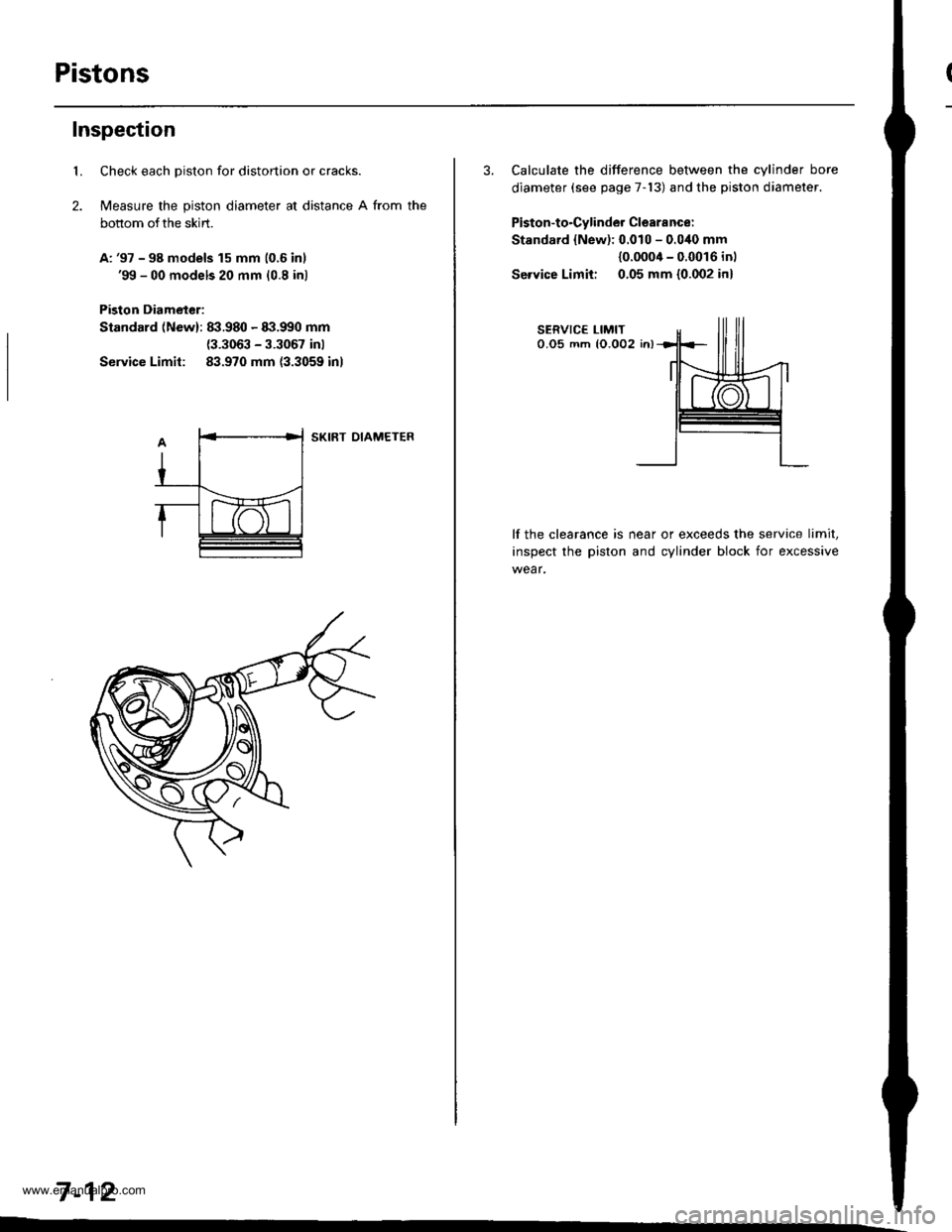
PistonsI
Inspection
LCheck each piston for distortion or cracks.
Measure the piston diameter at distance A from the
bottom of the skirt.
A: '97 - 98 models 15 mm 10.5 inl'99 - 00 models 20 mm 10.8 inl
Piston Diameter:
Standard (New): 8:1.980 - txl.990 mm(3.3063 - 3.3067 inl
Service Limit: 83.970 mm {3.3059 inl
SKIRT DIAMETER
7-12
3. Calculate the difference between the cylinder bore
diameter (see page 7-13) and the piston diameter.
Piston-to-Cylinder Clearance:
Standard {New): 0.010 - 0.040 mm
{0.0004 - 0.0016 inl
Service Limit: 0.05 mm {0.002 in}
lf the clearance is near or exceeds the service limit,
inspect the piston and cylinder block for excessive
wear.
www.emanualpro.com