Bearing HONDA CR-V 2000 RD1-RD3 / 1.G Owner's Manual
[x] Cancel search | Manufacturer: HONDA, Model Year: 2000, Model line: CR-V, Model: HONDA CR-V 2000 RD1-RD3 / 1.GPages: 1395, PDF Size: 35.62 MB
Page 434 of 1395
Pressure Plate
Removal/lnspection
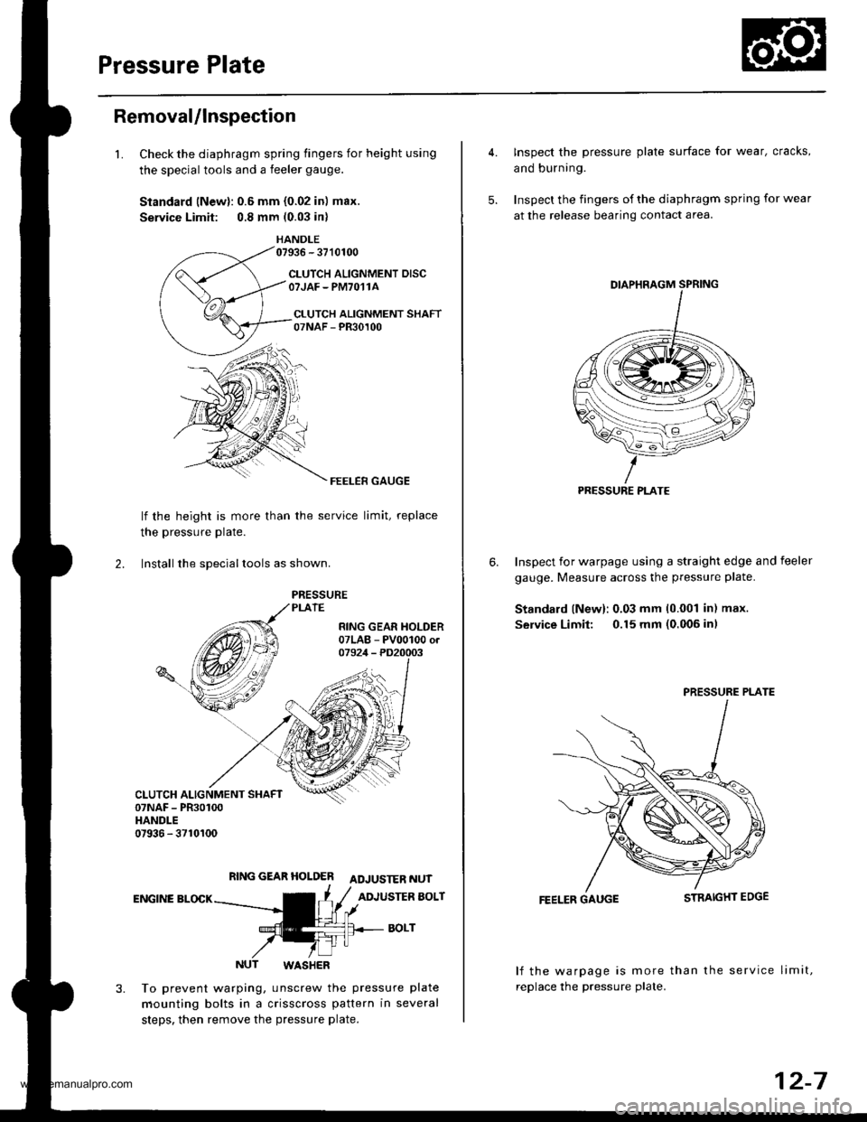
1.Check the diaphragm spring fingers for height using
the special tools and a feeler gauge.
Standard lNewl: 0.6 mm {0.02 in) max.
Service Limit: 0.8 mm (0.03 in)
HANDLE07936 - 3710100
CLUTCH ALIGNMENT DISCOTJAF - PM7O11A
CI.UTCH ALIGNMENT SHAFT07NAF - PR30100
FEELER GAUGE
lf the height is more than
the pressure Plate.
the service limit, replace
2. lnstall the sDeciallools as shown.
RING GEAR HOLDER ADJUSTER NUT
ENGINE BLOCKADJUSTER BOLT
BOLT
NUT WASHER
To prevent warping, unscrew the pressure plate
mounting bolts in a crisscross pattern in several
steps. then remove the pressure plate.
4. Inspect the pressure plate surface for wear, cracks,
and burning.
5. Inspect the fingers of the diaphragm spring for wear
at the release bearing contact area.
Inspect for warpage using a straight edge and feeler
gauge. Measure across the pressure plate.
Standard lNew): 0.03 mm 10.001 in) max.
Service Limit: 0.15 mm (0.006 inl
6.
FEELER GAUGE
lf the warpage is more than the service limit,
replace the pressure plate.
PRESSURE PLATE
PRESSURE PLATE
12-7
www.emanualpro.com
Page 436 of 1395
Flywheel
Inspection
2.
3.
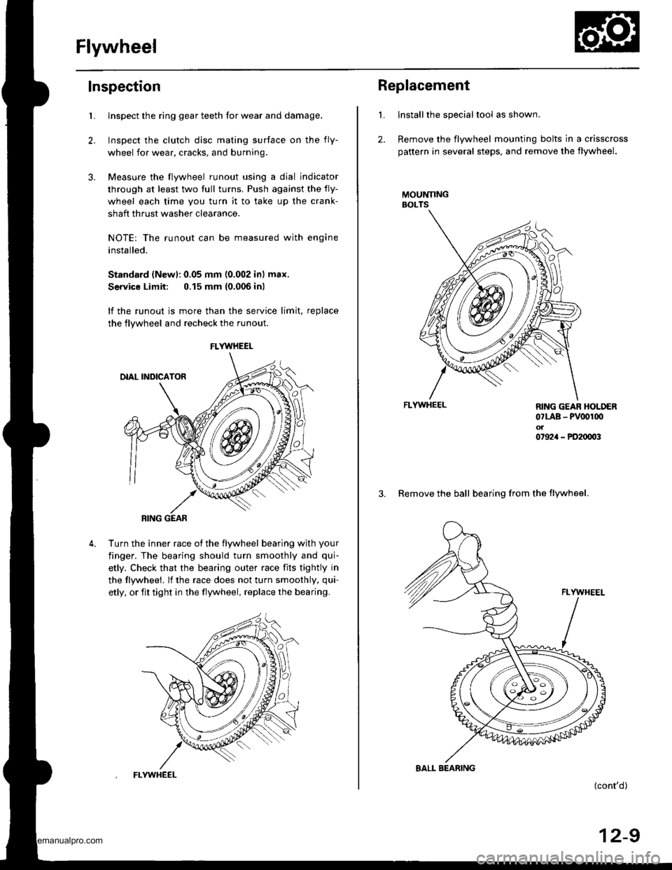
Llnspect the ring gear teeth for wear and damage.
Inspect the clutch disc mating surface on the fly-
wheel for wear, cracks, and burning
Measure the flywheel runout using a dial indicator
through at least two full turns. Push against the fly-
wheel each time you turn it to take up the crank-
shaft thrust washer clearance.
NOTE: The runout can be measured with engine
installed.
Standard (Newl: 0.05 mm (0.002 in) max.
Service Limit: 0.15 mm {0.006 inl
lf the runout is more than the service limit, replace
the flywheel and recheck the runout
Turn the inner race ot the flywheel bearing with your
finger. The bearing should turn smoothly and qui-
etly. Check that the bearing outer race fits tightly in
the tlywheel. lf the race does not turn smoothly, qui-
etly, or fit tight in the flywheel, replace the bearing.
FLYWHEEL
RING GEAR
FLYWHEEL
L
2.
Replacement
Installthe special tool as shown.
Remove the flywheel mounting bolts in a crisscross
pattern in several steps, and remove the flywheel.
MOUNNNGBOLTS
FLYWHEEL
(cont'd)
12-9
RING GEAR HOLDER07LAB - PV00r00ol07924 - PD20003
3. Remove the ball bearing from the flywheel.
BALL BEARING
www.emanualpro.com
Page 437 of 1395
FlywheelClutch Disc, Pressure Plate
Replacement (cont'dl
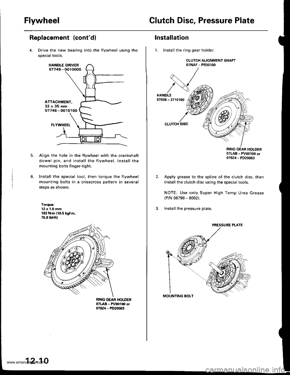
Drive the new bearing
specialtools.
HANOLE DRIVER07749-
ATTACHMET{T-32x35mm07746 -O010100
FLYWHECI-
Align the hole in the flywheel with the crankshaft
dowel pin, and install the flywheel. Install the
mounting bolts finger-tight.
Install the special tool, then torque the flywheel
mounting bolts in a crisscross pattern in several
steps as shown.
Torque:12 x 1.0 mmr03 N.m (10.5 kgl.ln,75.9 tbtftl
into the flywheel using the
12-10
Installation
1. Install the ring gear holder.
CLUTCH ALIGNMENT SHAFT07NAF - PR30100
CLUTCH DISC
RING GEAR HOLDER07LAB _ pvoot(x) or07924 _ PD20003
Apply grease to the spline of the clutch disc, then
install the clutch disc using the special tools.
NOTE: Use only Super High Temp Urea Grease(P/N 08798 - 9002).
lnstall the pressure plate.
PRESSURE PLATE
www.emanualpro.com
Page 438 of 1395
Release Bearing
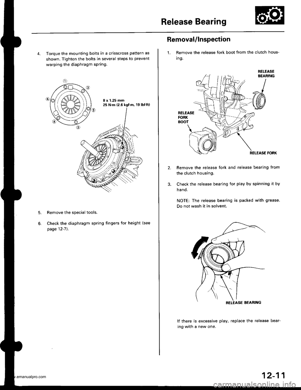
4. Torque the mounting bolts in a crisscross pattern as
shown. Tighten the bolts in several steps to prevent
warping the diaphragm spring.
8 x 1.25 mm25 N.m (2.6 kgf.m, 19lbfft)
Remove the special tools.
Check the diaphragm spring fingers for height (see
page 12-7]'.
5.
6.
Removal/lnspection
1. Remove the release fork boot from the clutch hous-
Ing.
RELEASEBEABING
RELEASEFORKBOOT
\
RELEASE FORK
Remove the release fork and release bearing from
the clutch housing.
Check the release bearing for play by spinning it by
ha nd.
NOTE: The release bearing is packed with grease.
Do not wash it in solvent.
lf there is excessive play, replace the release bear-
ing with a new one.
12-11
www.emanualpro.com
Page 439 of 1395
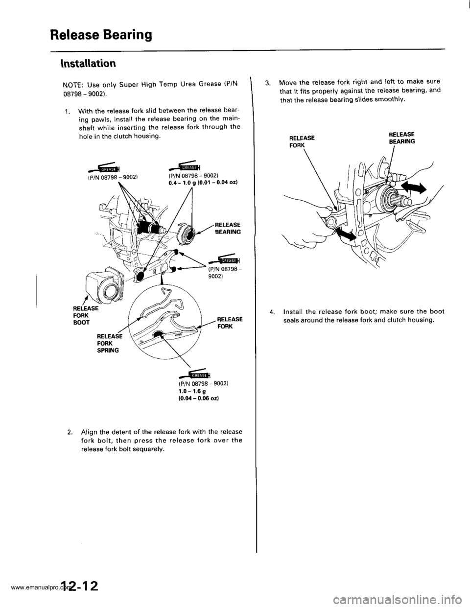
Release Bearing
lnstallation
NOTE: Use only Super High Temp Urea Grease (P/N
08798 - 9002).
1. With the release fork slid bet\iveen the release bear-
ing pawls. install the release bearing on the main-
shaft while inserting the release tork through the
hole in the clutch housing.
lPlN 08798 - 9002)0.,1- 1.0 I (0.01 - 0 04 ozl
(P/N 087989002)
(P/N 08798 9002)
1.0 - 1.6 g
{0.0,1 - 0,06 ozl
-6.l(P/N 08798 -
r iz]))
| (,4\1t1t
/\[wRELEASEFORKBOOT
Align the detent of the release fork with the release
fork bolt, then press the release fork over the
release fork bolt sequarelv.
12-12
3. Move the release lork right and left to make sure
that it tits properly against the release bear'rng. and
that the release bearing slides smoothlY.
Install the release tork boot; make sure the boot
seals around the release fork and clutch housing.
4.
www.emanualpro.com
Page 440 of 1395
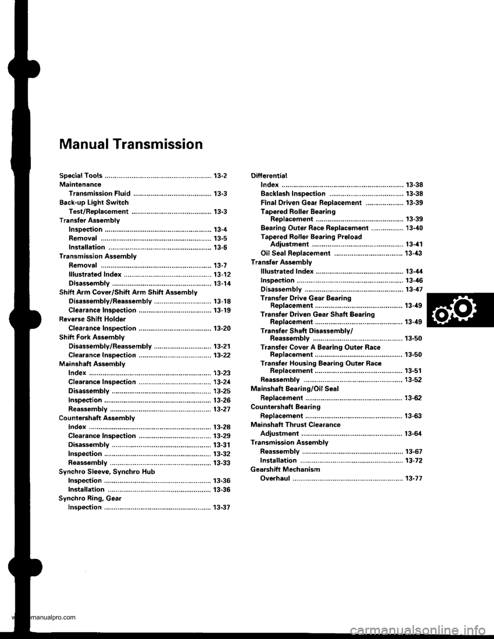
Manual Transmission
Diff€rential
lndex ...................... ......... 13-38
Backlash Inspestion ..,....,.,.....................,......, 13-38
Final Driven Gear Replacement .................... 13-39
Tapered Roller BearingReplacement ............. 13-39
Bearing Outer Race Replacement ......,.,........ 13-i10
Tapered Roller Bearing PreloadAdiustment ............... 13-il1
Oil Seal Reolacement .................................... 13-/l:}
Transfer Assembly
lllustrated Index ............. 13-il4
Inspection ..,....,.,......,...... 13-46
Disassembly ................... 13-47
Transfer Drive Gear BearingReplacement ...,..................,....................... 13-ilg
Transfer Driven Gear Shaft BearingReplacement .............................................. 13-ilg
Transfer Shaft Disassembly/Reassembly .............. 13-50
Transler Cover A Bearing Outer RaceRep1acement.........,.,.,..........,....,...,.........,., 13-50
Transter Housing Bearing Outer RaceReD1acement.............................................. 13-51
Reassembly ..-............,... 13-52
Mainshaft Bearing/Oil Seal
Beplacement .................. 13-62
Countershaft Bearing
Replacement .,,.,.,., ..,...... 13-63
Mainshaft Thrust Clearance
Adiustment .................... 13-6,1
Transmission Assembly
Reassembly .,.,.,.,..,.,....,., 13-67
fnstaffation .,.,.............,... 13-72
Gearshift Mechanism
Overhaul ................ .........13-17
www.emanualpro.com
Page 441 of 1395
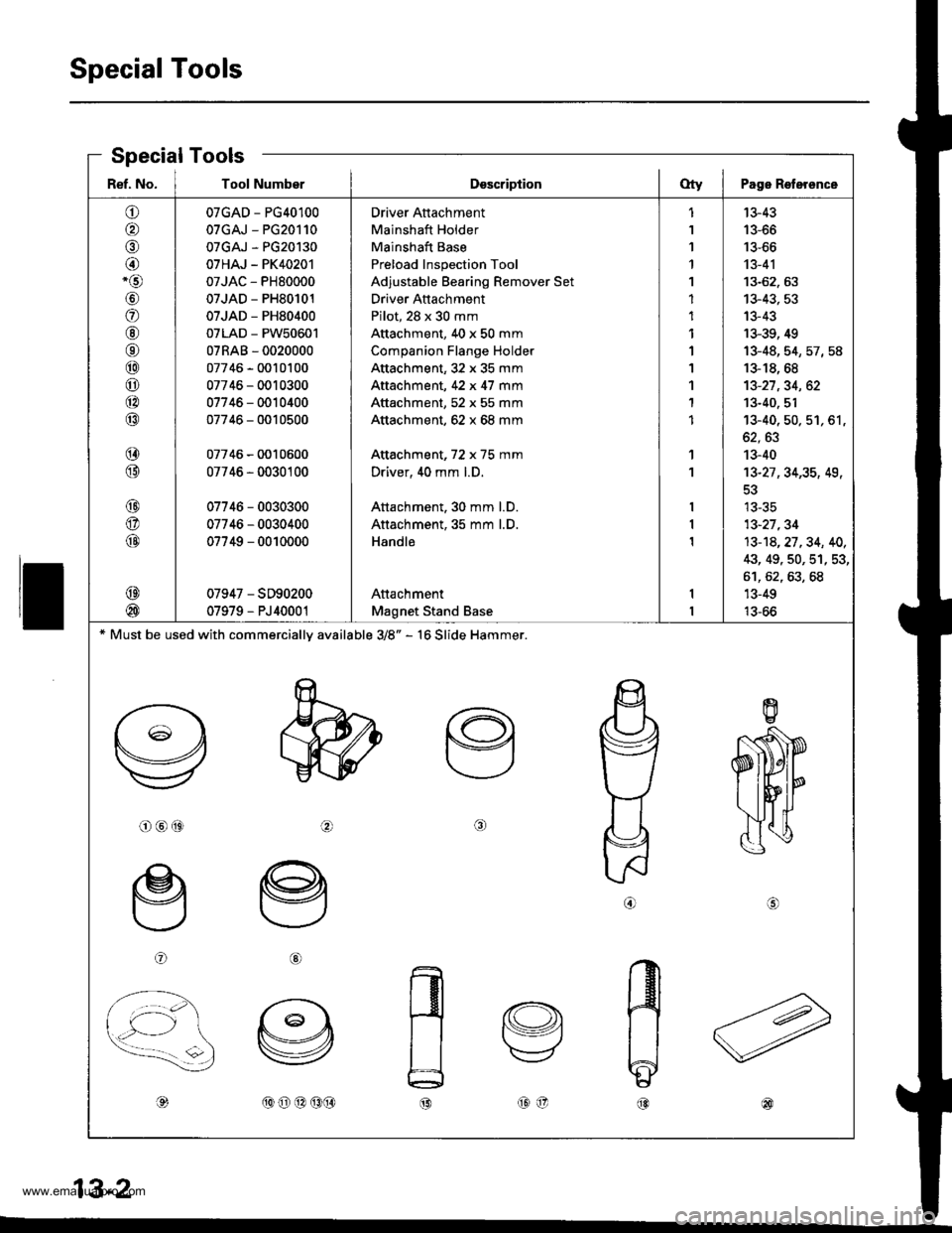
Special Tools
ll
Ref. No. I Tool NumberDsscriptionOty I Page Roterence
o
o,6)
@-o
\9'
a
@6r
@
o
@
@
@
@
@
@
@
@
@
07GAD - PG40100
07GAJ - PG20110
07GAJ - PG20130
07HAJ - PK40201
07JAC - PH80000
07JAD - PH80101
07JAD - PH80400
07LAD - PW50601
07RAB - 0020000
07746 - 0010100
07746 - 0010300
07746 - 0010400
07746 - 0010500
07746 - 0010600
07746 - 0030100
07746 - 0030300
07746 - 0030400
07749 - 0010000
07947 - SD90200
07979 - PJ40001
Driver Attachment
Mainshaft Holder
Mainshaft Base
Preload Inspection Tool
Adjustable Bearing Remover Set
Driver Attachment
Pilot, 28 x 30 mm
Attachment, 40 x 50 mm
Companion Flange Holder
Attachment,32 x 35 mm
Attachment, 42 x 47 mm
Attachment, 52 x 55 mm
Attachment, 62 x 68 mm
Attachment, 72 x 75 mm
Driver, 40 mm l.D.
Attachment. 30 mm l.D.
Attachment, 35 mm l.D.
Handle
Attachment
Magnet Stand Base
1
1
1'l
1
1
1
1
1
1'I
1
1
1
1
13-43
13-66
13-66
13-41
13-62. 63
13-43, 53
13-43
13-39, 49
13-48,54,57,58
13-18, 68
13-27,34, 62
13-40. 51't3-40, 50. 51, 61,
oz, oJ
13-40
13-27 ,34,35, 49,
tJ-5C
13-27,34
13-14,27.34, 40,
43, 49, 50, 51, 53,
61,62,63,68'13-49
13-66
* Must be used with commercially available 3/8" - 16 Slide Hammer.
o@(9ta\
oG)
,d,(oo@(9(}@o@
.A IAa 5-z
Special Tools
www.emanualpro.com
Page 450 of 1395
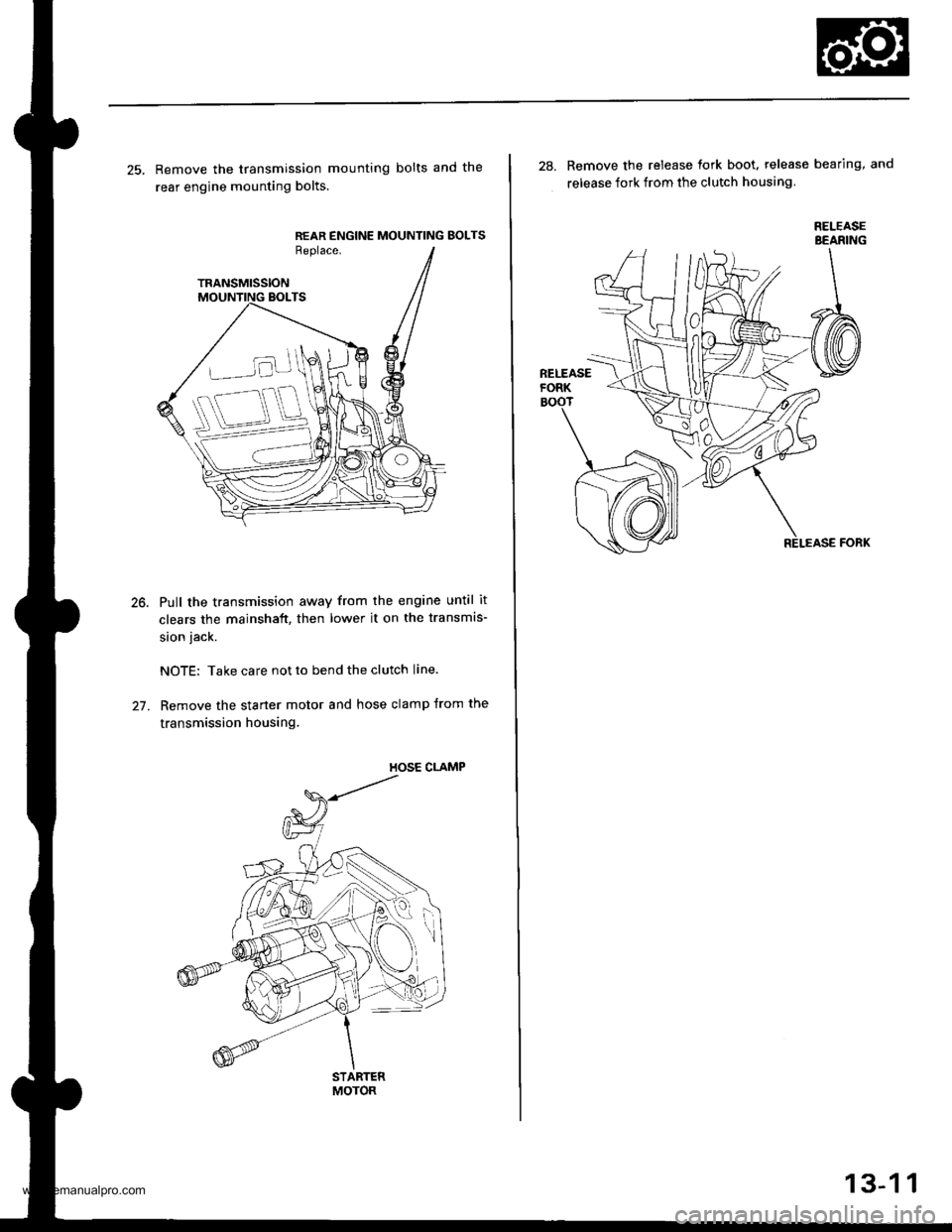
25. Remove the transmission mounting bolts and the
rear engine mounting bolts.
REAR ENGINE MOUNTING BOLTSReplace.
TRANSMISSION
Pull the transmission away from the engine until it
clears the mainshaft, then lower it on the transmis-
sion jack.
NOTE: Take care not to bend the clutch line.
Remove the starter motor and hose clamp from the
transmission housing.
STARTERMOTOR
28. Remove the release tork boot. release bearing, and
release fork from the clutch housing
RELEASEBEANING
13-1 1
www.emanualpro.com
Page 451 of 1395
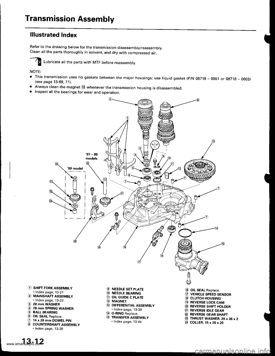
Transmission Assembly
lllustrated Index
Refer to the drawing below for the transmission disassembly/reassembly.Clean all the pans thoroughly in solvent, and drv with comoressed air.
I LuUri""r" utt the parts with MTF before reassembly.
NOTE:
t This transmission uses no gaskets between the major housings; use liquid gasket (p/N 0g718 - 0001 or oE7l8 - 0003)(see page 13-69, 71).. Always clean the magnet @ whenever the transmissjon housing is disassembled.. Inspect all the bearings for wear and operation.
C) sHrFr FoRK ASSEMBLY.Index page, l3-21(a MAINSHAFT ASSEMBLY.Index page, 13-23(9 28 mm WASHER€) 28 mm SPRTNG WASHERO BALL BEARINGa6) OIL SEAL ReDlace.(D 14 x 20 mm DOWEL ptN
G) couNTERSHAFT ASSEMBLY.lndex page, 13-28
NEEDLE SET PLATENEEDLE BEARINGOIL GUIOE C PLATEMAGNETDIFFERENTIAL ASSEMBLY.lndex page, 13-38O-nlNG Beplace.TRANSFER ASSEMBLY.Index page, '13,44
OIL SEAL Replace.VEHICLE SPEED SENSORCLUTCH HOUSINGREVERSE LOCK CAMREVEESE SHIFT HOLDERREVERSE IDLE GEARREVERSE GEAR SHAFTTHRUST WASHER,20 x 36 x 2COLLER, 15 x 20 x 20
aol
@o@@
(D
i9
@@@(9
@@@e3@
13-12
www.emanualpro.com
Page 462 of 1395
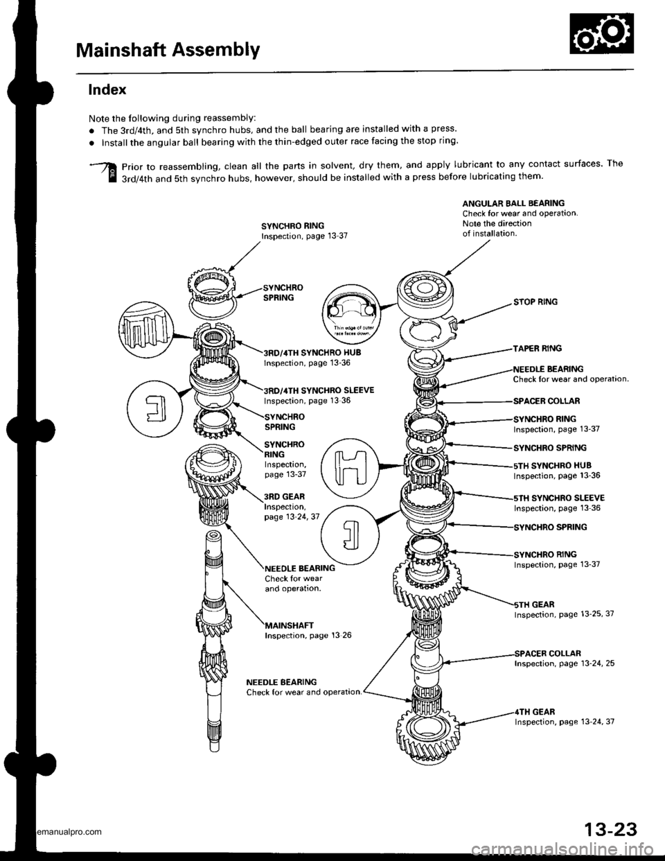
Mainshaft Assembly
lndex
Note the Iollowing during reassembly:
. The 3rd/4th, and 5th synchro hubs, and the ball bearing are installed with a press.
. Installthe angular ball bearing with the thin-edged outer race facing the stop ring
prior to reassembling, clean all the parts in solvent, dry them, and apply lubricant to any contact surfaces. The
3rd/4th and 5th svnchro hubs, however, should be installed with a press before lubricating them'
ANGULAR EALL BEARINGCheck for wear and operation.Note the directionof installation.SYNCHRO RINGInspection, page l3 37
SYNCHRO HUBlnspection, page 13-36
SYNCHRO SLEEVEInspection, page 13 36
SPRING
SYNCHRO
SYOP RING
TAPER RING
BEARINGCheck Ior wear and operataon.
COLLAR
RINGInspection, page 13-37
SYNCHRO SPRING
SYNCHRO HUBInspection, page 13_36
SYNCHRO SLEEVEInspection, page 13 36
SPFING
RINGInspection, page 13_37
GEARInspection, page 13_25, 37
COLLARInspection, page 13-24, 25
GEARInspection, page 13 24, 37
Inspection,page 13-37
3RD GEARInspeclton,page 13 24,37
BEARINGCheck for wearano operalton.
Inspection, page 13 26
NEEDLE BEARINGCheck for wear and operat,on.
13-23
www.emanualpro.com