No start HONDA CR-V 2000 RD1-RD3 / 1.G Owner's Manual
[x] Cancel search | Manufacturer: HONDA, Model Year: 2000, Model line: CR-V, Model: HONDA CR-V 2000 RD1-RD3 / 1.GPages: 1395, PDF Size: 35.62 MB
Page 77 of 1395
R'oR
l
u
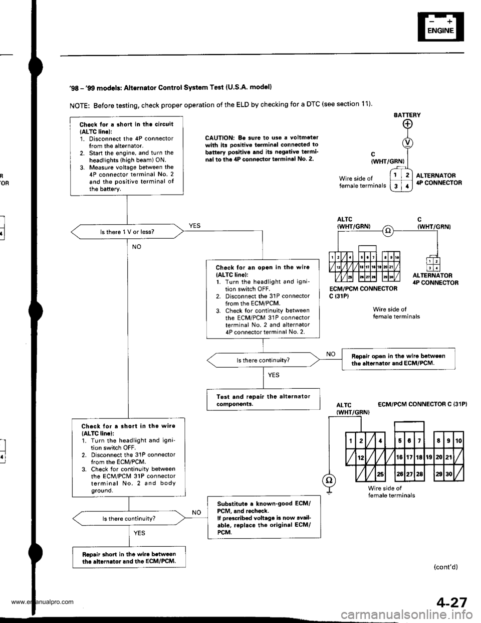
'98 -'9O modols: Alternator Contlol SYstem Te3t (U.S.A' model)
NOTE: Before testing, check proper operation of the ELD by checking for a DTC (see section 11)
EATTERY
CAUTION: Be surc to uso a voltmetorwith its oo3itive torminel connccted to
battery po3hivo tnd its negativo teami'
nal to the 4P connector torminal No 2.
ECM,/PCM CONNECTORc {31P)
Wire side olfemale terminals
cIWHT/GRN)
Wire side oltemale terminals
ALTERNATOR4P CONNECTOR
ALTC
IWHT/GBNI
ECM/PCM CONNECTOR C {31P}
(cont'd)
Chock tor . short in tha circuit
IALTC lino):1. Disconnoct the 4P connectorIrom the alternator.2. Start the engine, and turn the
headlights (high beam) ON.
3. Measure voltage between the4P connector terminal No. 2
and the positive terminal oIthe battsry.
lsthere 1V or less?
Check for an opon in the wire
IALTC line):1. Turn the headlight and igni-
tion switch OFF.2. Disconnect the 31P connectorfrom the ECM/PCM.3. Check tor continuity betweenth6 ECM/PCM 31P connectorterminal No. 2 and alternator4P connector terminal No. 2.
Ropair open in the wiro betweenthe ahornrtor and ECM/PCM.
Chack lor a rhort in tho wire
{ALTC lincl:'!. Turn the headlight and igni'tion switch OFF.2. Disconnect the 31P connectorIrom the ECM/PCM.3. Ch6ck for continuity betweenthe ECM/PCM 31P connectorterminal No. 2 and bodyground.
Substituto . known-good ECM/
PCM, .nd rochock.lf prdcdb€d voltage b now av.il-able, repl.ce the original ECM/
rcM.
Rcpair rhort in thc wire b.twconth. ahGrn.tol.nd the EcM/PcM.
4-27
www.emanualpro.com
Page 78 of 1395
Gharging System
Troubleshooting (cont'd)
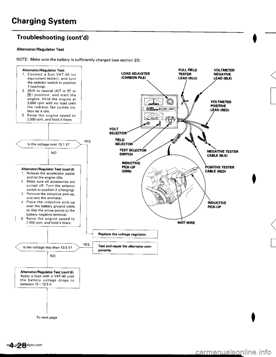
Alternator/Regulator Test
NOTE: Make sure the battery is sufficiently charged (see section 23).
FIELDSELECTOR
TESTswtTcH
I
VOLTMEIERPOSmVEt
NEGATIVE TESTERCABI.E {BLKI
(BED)
TESTERINDUCTIVEPICK.UP{GRN)CABLE IREDIAhernator/Regulator Test (cont'd)lI� Release the accelerator pedal,and let the engine idle.2 Make sure all accessories areturned off. Turn the selectorswitch to posjtion 2 (charging).3 Remove the inductive pick up,and zero the ammeter.{ Place the inductive pick-upover the battery ground cableso that the arrow points to thebaftery negative terminal.5. Raise the engine speed to2 000 rpm, and hold ir there.
I
(
T
I
WHT WIRE
Alternator/Regulator Test:1. Connect a Sun VAT-40 (orequrvalent tester), and turnthe selector switch to position1{sraning).2. Shift to neutral (A/T in E orN) position, and start theengane. Hold the engine at3,000 rpm with no load untilthe radiator fan comes on,then let it idle.3. Raise the engine speed to2,000 rpm, and hold it there.
ls the voltage over 15.1 V?
ls the voltage less than 13.5 V?
Altarnator/Regulator Test (cont'd:Apply a load with a VAT-40 untilthe battery voltage drops tobetween 12 - 13.5 V.
To next page
4-28
www.emanualpro.com
Page 89 of 1395

Disconnest the lilP connector from the control unit.
Csvity WireTest condition
R€conn€ct tho 14P connGctor to the control unit.
Test: Desired resultPossible cause it result is not obtained
BRNAr'VHTUnder all conditionsCheck for resistance to groundl
There should be 80 - 120 o.
Faulty actuator solenoid
Poor ground (G202)
An open in the wire1BRNUnder all conditionsCheck for resistance to groundl
There should be 40 - 60 0.
11BRN/BLKUnder all conditionsCheck for resistance to ground:
There should be 70 - 110 O.
2GRY
lgnition switch ON (ll),
main switch ON and
brake pedal depressed,
then released
Check for voltage to ground:
There should be 0 V with the pedal
depressed and battery voltage with
the pedal released.
. Faulty brake switch. An open in the wire
BLKUnder all conditionsCheck for continuity to ground:
There should be continuity.
. Poor ground (G401). An open in the wire
5GRNMHT
Brake pedal depressed,
then released
Check for voltage to ground:
There should be battery voltage with
the pedal depressed, and 0 V with
the pedal released.
Blown No.52 1'15 Alfuse in the
under-hood fuse/relay box
Faulty brake switch
An open in the wire
LT GRN/
RED
Set button pushedCheck for voltage to ground:
There should be battery voltage.Blown No. 52 {'15 A} fuse in the
under-hood fuse/relay box
Faulty horn relay
Faulty sevresume switch
Faulty cable reel
An open in the wire7LT GRN/
BLK
Resume button pushed
10RED/BLU
lgnition switch ON lll)Attach to ground:
Cruise indicator light in the gauge
assembly should come on.
Elown bulbBlown No. 25 (7.5 A) tuse in theunder-dash fuse/relay box
Faulty dimming circuit in the gauge
assembly
An open in the wire
ELU^r'r'HT
lgnitjon switch ON {ll}and main switch ON;
raise the front of the
vehicle, block one wheel
and rotate the other
wheel slowly.
Check for voltage between the
ELUA/VHT @ and BLK O terminalsl
There should be 0 - 5 V or more-0 - 5 V or more repeatedly.
Faulty vehicle speed sensor (VSS)
An open in the wire
r3LT GRN
lgnition switch ON {ll}and main switch ONCheck for voltage to ground:
There should be battery voltage.
Blown No. 14 (7.5 A) fuse in theunder-dash fuse/relay box
Faulty main switch
An open in the wire
l4PNK
A'/T: Shift lever in E, EotE
lvl/T: Clutch pedal
releaseo
Check for continuity to ground:
There should be continuity.NOTE: There should be no continu-
ity when the shift lever is in otherpositions or when the clutch pedal is
oepresseo.
Faulty A/f gear position switch 1A,/TlFaulty or misadjusted clutch switch
fi{/r)Poor ground (G101)
An open in the wire
BLU
Start tho engine. turnthe main switch ON, anddrive the vehicle over 25
mph (40 km/h)with the
crurse control set
Check for voltage to ground:
There should be approx.5 V
. Faulty cruise control unit. Shod to ground
*: '98 - 00 models with Automatic Transmission.
4-39
www.emanualpro.com
Page 93 of 1395
Actuator Cable Adiustment
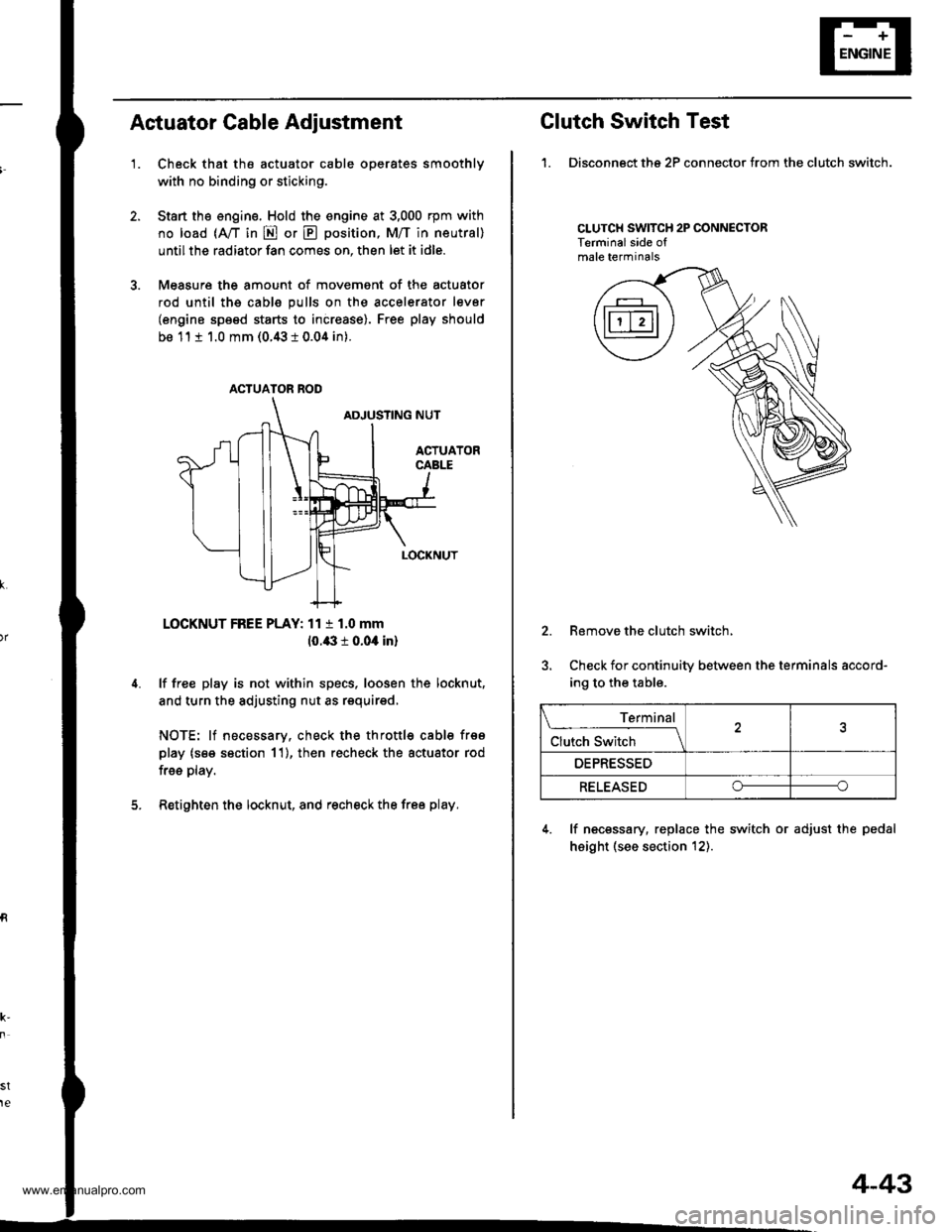
'1.Check that the actuator cable operates smoothly
with no binding or sticking.
Start the engine. Hold the engine at 3,000 rpm with
no load (A,/T in E or E position, M/T in neutral)
until the radiator fan comes on, then let it idle.
Measure the amount of movement of the actuator
rod until ths cable pulls on the accelerator lever
(engine speed starts to increase). Free play should
be 11 t 1.0 mm (0.43 i 0.04 in).
LOCKNUT FREE PLAY: 11 t 1.0 mm
10.43 r 0.04 in)
lf free play is not within specs, loosen the locknut,
and turn the adjusting nut as requirsd,
NOTE: lf necessary, check the throttl€ cable frso
play (s€e section 11), then recheck the actuator rod
free play.
Retighten the locknut, and recheck the free play.
st
te
ACTUATOR ROD
Clutch Switch Test
1. Disconngct ths 2P connector from the clutch switch.
CLUTCH SWITCH 2P CONNECTORTerminalside ofmale terminals
2.
5.
Remove the clutch switch,
Check for continuity between the terminals accord-
ing to the table.
4. lf necessary, replace the switch or adjust the pedal
height (see section t2).
Terminal
Clutch Switch \
OEPRESSED
RELEASEDoo
4-43
www.emanualpro.com
Page 112 of 1395
Engine Removal/lnstallo cton
Installation (cont'd)
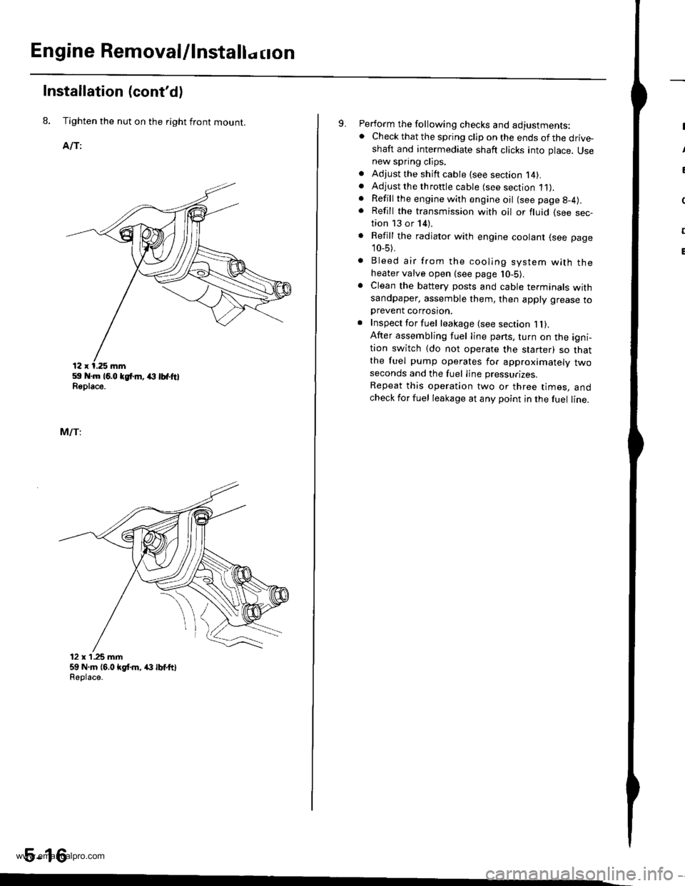
8. Tighten the nut on the right front mount.
AlTi
59 .m 16.0 tgt m, (l lbfftlReplace.
MlTi
12 x'1.25 mm59 N.m 16,0 kgt m, /(} lbt ttlReolace.
5-16
9. Perform the following checks and adjustments:. Check that the spring clip on the ends of the drive-shaft and intermediate shaft clicks into place. Usenew spring clips.. Adjust the shift cable (see section l4).. Adjust the throttle cable (see section 11).. Refill the engine with engine oil (see page g-4).
. Refill the transmission with oil or fluid (see sec-tion 13 or 14).
. Refill the radiator with engine coolant (see page
10_5).
. Bleed air from the cooling system with theheater valve open (see page l0-5).. Clean the battery posts and cable terminals withsandpaper, assemble them, then apply grease toDrevent corrosron.. Inspect for fuel leakage (see section 1l).After assembling fuel line pans, turn on the igni-tion switch (do not operate the starter) so thatthe fuel pump operates for approximately twoseconds and the fuel Iine pressurizes.
Repeat this operation two or three times, andcheck for fuel leakage at any point in the fuel line.
www.emanualpro.com
Page 153 of 1395
Main Bearings
2.
3.
1.
4.
Clearance
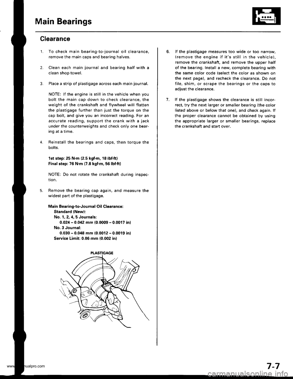
To check main bearing-to-journal oil clearance,
remove the main caps and bearing halves.
Clean each main journal and bearing half with a
clean shop towel.
Place a strip of plastigage across each main journal.
NOTE: lf the engine is still in the vehicle when you
bolt the main cap down to check clearance, the
weight of the crankshaft and flywheel will flatten
the plastigage further than just the torque on the
cap bolt, and give you an incorrect reading. For an
accurale reading, support the crank with a jack
under the counterweights and check only one bear-
Ing aI a Irme.
Reinstall the bearings and caps, then torque the
bolts,
1st step:25 N'm (2.5 kgf.m, 18lbf.ft)
Final siep: 76 N'm 17.8 kgl.m, 56 lbf.ftl
NOTE: Do not rotate the crankshaft during inspec-
tron.
Remove the bearing cap again, and measure the
widest part of the plastigage.
Main Bearing.to.Journal Oil Clearance:
Stand8.d {New):
No. 1,2,4,5 Journsls:
0.02i1- 0.0i12 mm (0.0009 - 0.0017 inl
No. 3 Journal:
0.030 - 0.0i18 mm (0.0012 - 0.0019 inl
Service Limit: 0.06 mm 10.002 in)
lf the plastigage measures too wide or too narrow,(remove the engine if it's still in the vehicle),
remove the crankshaft, and remove the upper half
of the bearing. Install a new, complete bearing with
the same color code (select the color as shown on
the next page). and recheck the clearance, Do not
file, shim, or scrape the bearings or the caps to
adjust the clearance.
lf the plastjgage shows the clearance is still incor-
rect, try the ne)d larger or smaller bearing {the color
listed above or below that one), and check again. lf
the proper clearance cannot be obtained by using
the appropriate larger or smaller bearings, replace
the crankshaft and start over.
7.
7-7
www.emanualpro.com
Page 154 of 1395
Main BearingsConnecting Rod Bearings
Selection
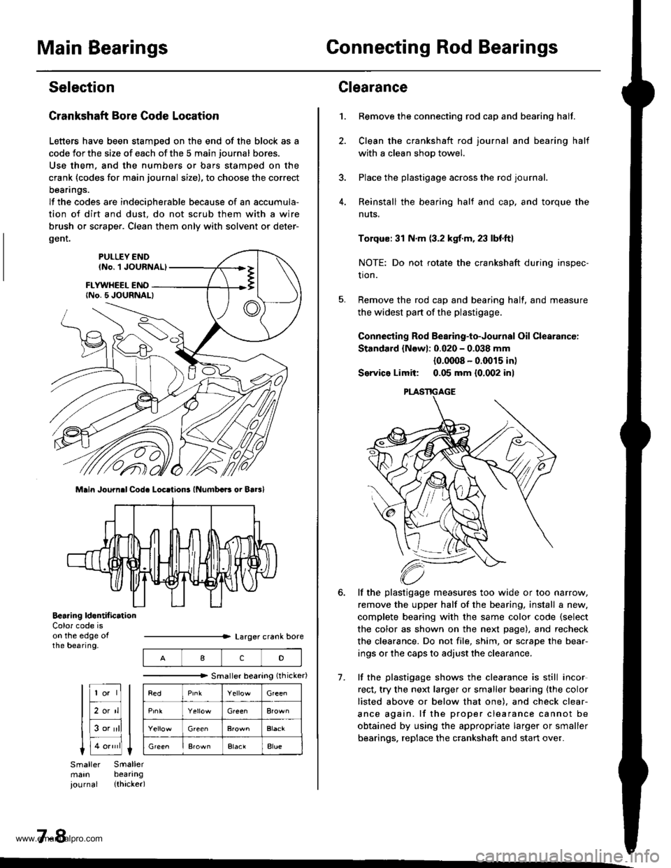
Crankshaft Bore Code Location
Letters have been stamDed on the end of the block as a
code Jor the size of each of the 5 main journal bores.
Use them, and the numbers or bars stamped on the
crank (codes for main journal size), to choose the correct
beanngs.
lf the codes are indecipherable because of an accumula-
tion of dirt and dust. do not scrub them with a wire
brush or sc.aper. Clean them only with solvent or deter-
gent.
Main Journ.l Cod. Locrtions lNumbcB oi Bar3l
Bearing ld.ntif icrtionColor code ison the edge ofthe bearing.
7-8
IcD
"""""""" Smallerbearing(rhicker)
Green
Green
ElaclAlue
Clearance
Remove the connecting rod cap and bearing half.
Clean the crankshaft rod journal and bearing half
with a clean shop towel.
Place the plastigage across the rod journal.
Reinstall the bearing half and cap, and torque the
nuts.
1.
7.
Torqus: 31 N.m (3.2 kgf.m. 23 lbf.ft)
NOTE: Do not rotate the crankshaft during inspec-
tion.
Remove the rod cap and bearing half, and measure
the widest part of the plastigage.
Connesting Rod Bearing-to-Journal Oil Clearancc:
Standard {Newl: 0.020 - 0.038 mm
{0.0008 - 0.0015 in)
Service Limit: 0.05 mm {0.002 inl
lf the plastigage measures too wide or too narrow,
remove the upper half of the bearing, install a new.
complete bearing with the same color code {select
the color as shown on the next page), and recheck
the clearance. Do not file, shim, or sc.ape the bear-
ings or the caps to adjust the clearance.
lf the plastigage shows the clearance is still incor
rect, try the next larger or smaller bearing {the color
listed above or below that one). and check clear-
ance again. lf the proper clearance cannot be
obtained by using the appropriate larger or smaller
bearings. replace the crankshaft and start over.
PLASTIGAGE
www.emanualpro.com
Page 169 of 1395
Oil Seals
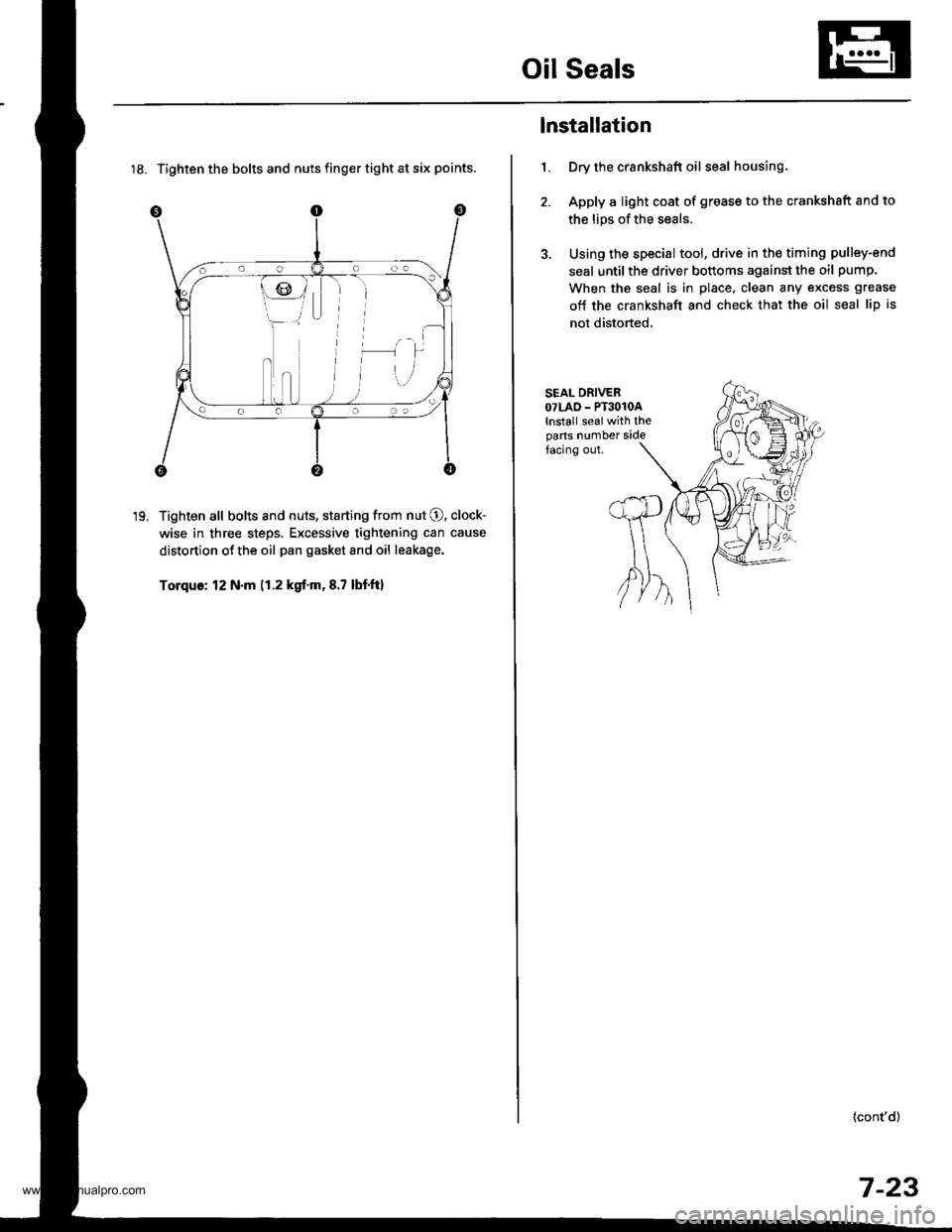
18. Tighten the bolts and nuts finger tight at six points.
Tighten all bolts and nuts, starting from nut O. clock-
wise in three steps. Excessive tightening can cause
distortion ot the oil pan gasket and oil leakage.
Torque: 12 N.m (1.2 kgt.m,8.7 lbtft)
19.
1.
lnstallation
Dry the crankshaft oil seal housing.
Apply a light coat of grease to the crankshsft and to
the lips of the seals.
Using the special tool, drive in the timing pulley-end
seal until the driver bottoms against the oil pump.
When the seal is in place, clean any excess grease
off the crankshaft and check that the oil seal lip is
not distorted,
SEAL DRIVEROTLAD - PT3O1OAlnstall sealwith theparts number sidefacing out.
(cont'd)
7-23
www.emanualpro.com
Page 177 of 1395
Oil Pressure SwitchOil Pressure
Testing
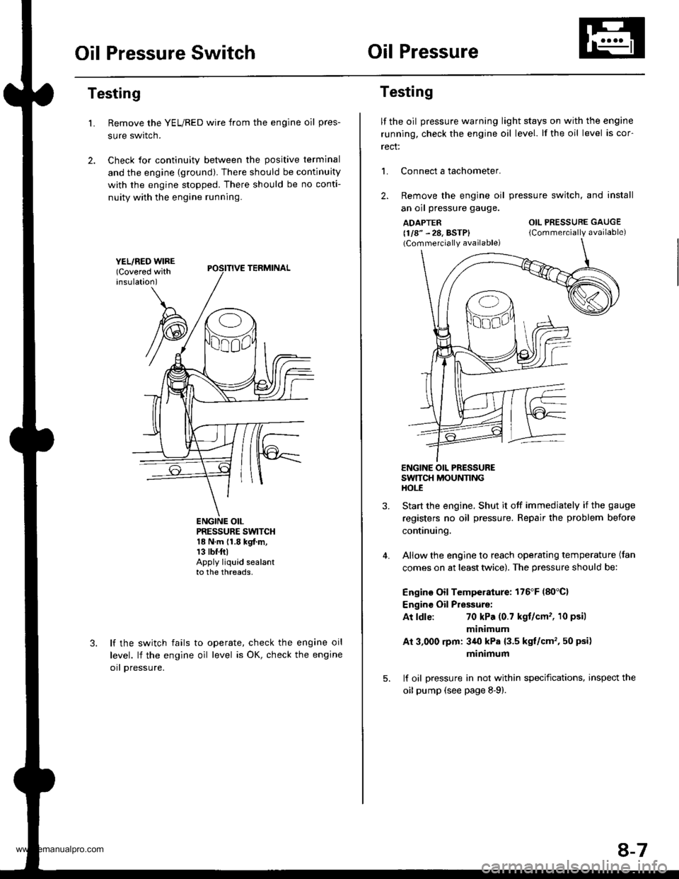
Remove the YEL/RED wire from the engine oil pres-
sure swrtcn.
Check for continuity between the positive terminal
and the engine {ground). There should be continuity
with the engine stopped. There should be no conti-
nuity with the engine running.
L
PRESSURE SWTCH18 N.m {1.8 kgf.m,13 tbr.ftlApply liquid sealantto the threads,
lf the switch fails
level. lf the engine
orl pressure.
to operate, check the engine oil
oil level is OK, check the engine
Testing
lf the oil pressure warning light stays on with the engine
running, check the engine oil level. lf the oil level is cor-
rect:
L Connect a tachometer.
2. Remove the engine oil
an oil pressure gauge.
ADAPTER(1/8" - 28, BSTP)(Commercially available)
pressure switch. and install
OIL PRESSURE GAUGE
{Commercially available)
4.
ENGINE OIL PRESSURESWTTCH MOUNNNGHOt-E
Start the engine. Shut it off immedjately if the gauge
registers no oil pressure. Repair the problem before
continuing.
Allow the engine to reach operating temperature (fan
comes on at least twice). The pressure should be:
Engino Oil Temperature: 176'F (80'C)
Engine Oil Pressure:
At ldle:70 kPa (0.7 kgt/cm'�, 10 psil
minimum
Ai 3,000 rpm: 3/r0 kPa {3.5 kgt/cm', 50 psi)
minimum
lf oil pressure in not within specifications, inspect the
oil pump (see page 8-9).
8-7
www.emanualpro.com
Page 194 of 1395
Radiator
Engine Coolant Refilling and Bleeding (cont'dl
Mix the recommended antifreeze with an equal
amount of water in a clean container.
NOTE:
. Always use Genuine Honda Antifreeze/Coolant.
Using a non-Honda coolant can result in corro-s\on, ca
sng t\e coo\
g sys\em \o ma\lunct\on
o. fail.
For best corrosion protection, the coolant con-
centration must be maintained year-round at50% minimum. Coolant concentrations less than
50% may not provide sufficient protection against
corrosion or freezing. Coolant concentrationsgreater than 60% will impair cooling efficiency
and are not recommended.
Do not use additional rust inhibitors or anti-rustproducts; they may not be compatible with the
coolant.
Engine Coolant Refill Capacity Iincluding 0.6 / 10.63US $, 0.53 lmp qtl for hoater and ressrvoirl:
A/T: 3.9 f {4.1 US $, 3.4 lmp qtl
M/T: 1.O t 14.2 US $, 3.5 lmp qrl
10-6
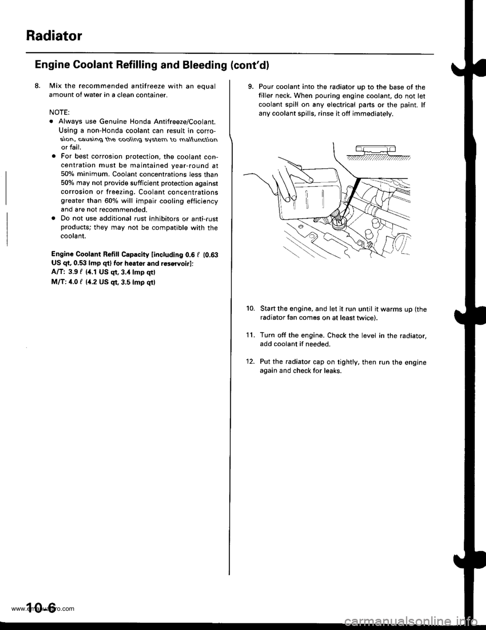
9. Pour coolant into the radiator uD to the base of the
filler neck. When pouring engine coolant. do not let
coolant spill on any electrical pans or the paint. lf
any coolant spills, rinse it oft immediately.
Start the engine, and let it run until it warms up (the
radiator fan comes on at least twice).
Turn off the engine. Check the level in the radiator,
add coolant if needed.
Put the radiator cap on tightly. then run the engine
again and check for leaks.
11.
10.
12.
www.emanualpro.com