ECO mode HONDA CR-V 2000 RD1-RD3 / 1.G Owner's Guide
[x] Cancel search | Manufacturer: HONDA, Model Year: 2000, Model line: CR-V, Model: HONDA CR-V 2000 RD1-RD3 / 1.GPages: 1395, PDF Size: 35.62 MB
Page 284 of 1395
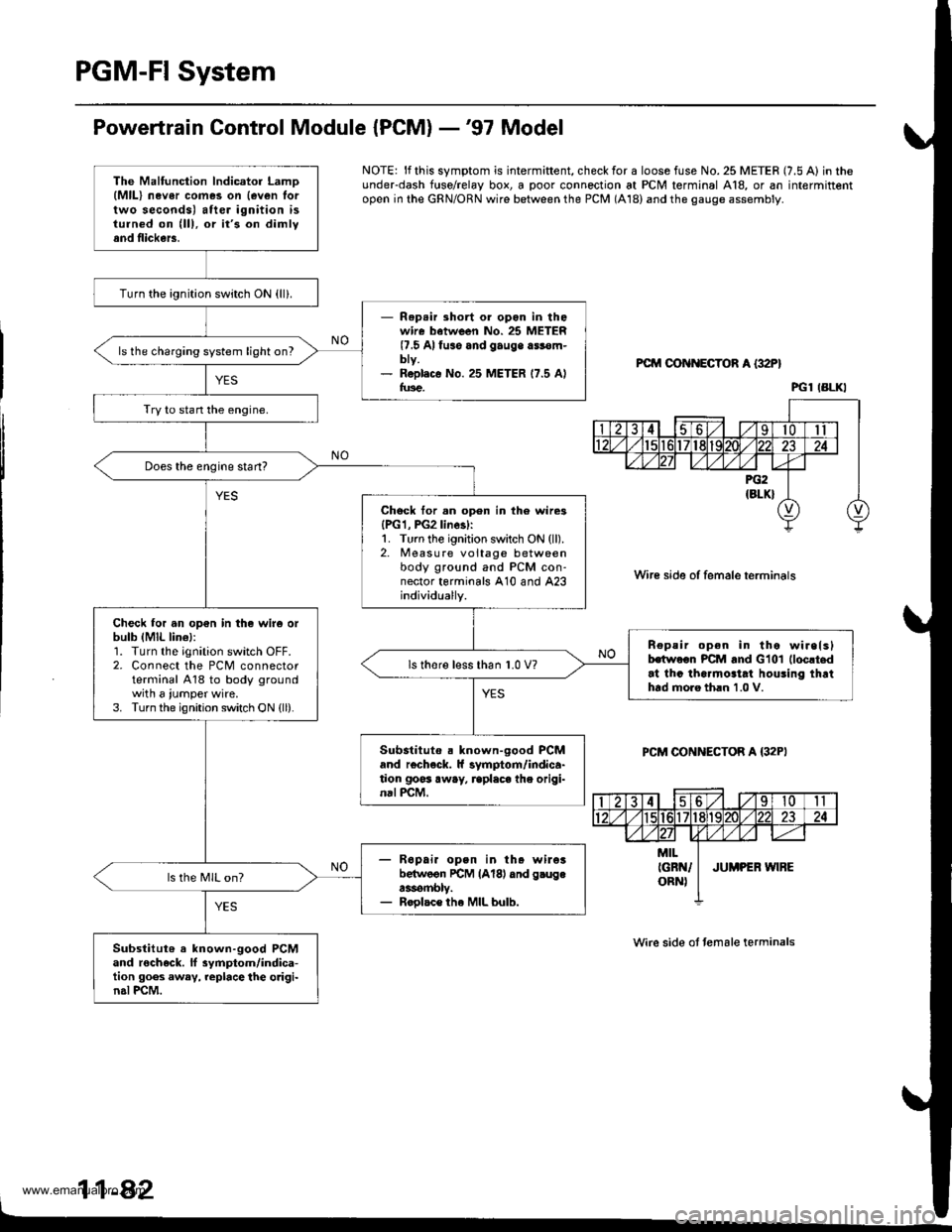
PGM-FI System
Powertrain Control Module {PCM} -'97 Model
NOTE: lf this symptom is intermiftent, check for a loose fuse No. 25 METER (7.5 A) in theunderdash f{rse/relay box, a poor connection at PCM terminal A18, or an intermittentopen in the GRN/ORN wire between the PCM (A18) and the gauge assembly.
PCM OON ECTOR A {32P}
Wire side of female terminals
PCM CONNECTOR A {32PI
Wire side ot temale terminals
11-42
The Malfunction lndicator LamD(MlL) nev6r comes on {even lortwo seconds) after ignition isturned on (lll, or it's on dimlyand flickers.
Turn the ignition switch ON {ll}.
- Rep.ir short or opon in thowire batween No. 25 METER(7.5 Alfuso and gauge a$€m-bty.- R6pl.c€ No. 25 METER 17.5 Alfus€.
ls the charging system light on?
Try to stan the engine.
Does the engine start?
Chock tor.n open in th6 wire3{PG1, PG2linesl:1. Turn the ignition switch ON (ll).2. Measure voltage betweenbody ground and PCM con-nector terminals A10 and A23individually.
Check for an op€n in the wir6 orbulb (MlL lin€l:1. Turn the ignition switch OFF.2. Connect the PCM connectorterminal A18 to body groundwith a iumper wire.3. Turn the ignition switch ON {ll).
n€peir open in tho wirelslhwoon PCM and Glol (loc!t.d
at thc tha.mo3tat houling thrthtd moro th.n 1.0 V.
ls thore l€ss than 1.0 V?
Substituto . known-good PCMand r€check. ll symptom/indica-tion goss away, rcplaca the origi-nal PCM.
- R6pai. open in th. wileibelwoon rcM lAl8l dnd g.ugea3rombly.- Roolac€ the MIL bulb.
ls the MIL on?
Substitut6 a known-good PCMand rocheck. ll 3ymptom/indica-tion goes away, replace the o.igi-n.l PCM.
PGl IBLKI
www.emanualpro.com
Page 290 of 1395
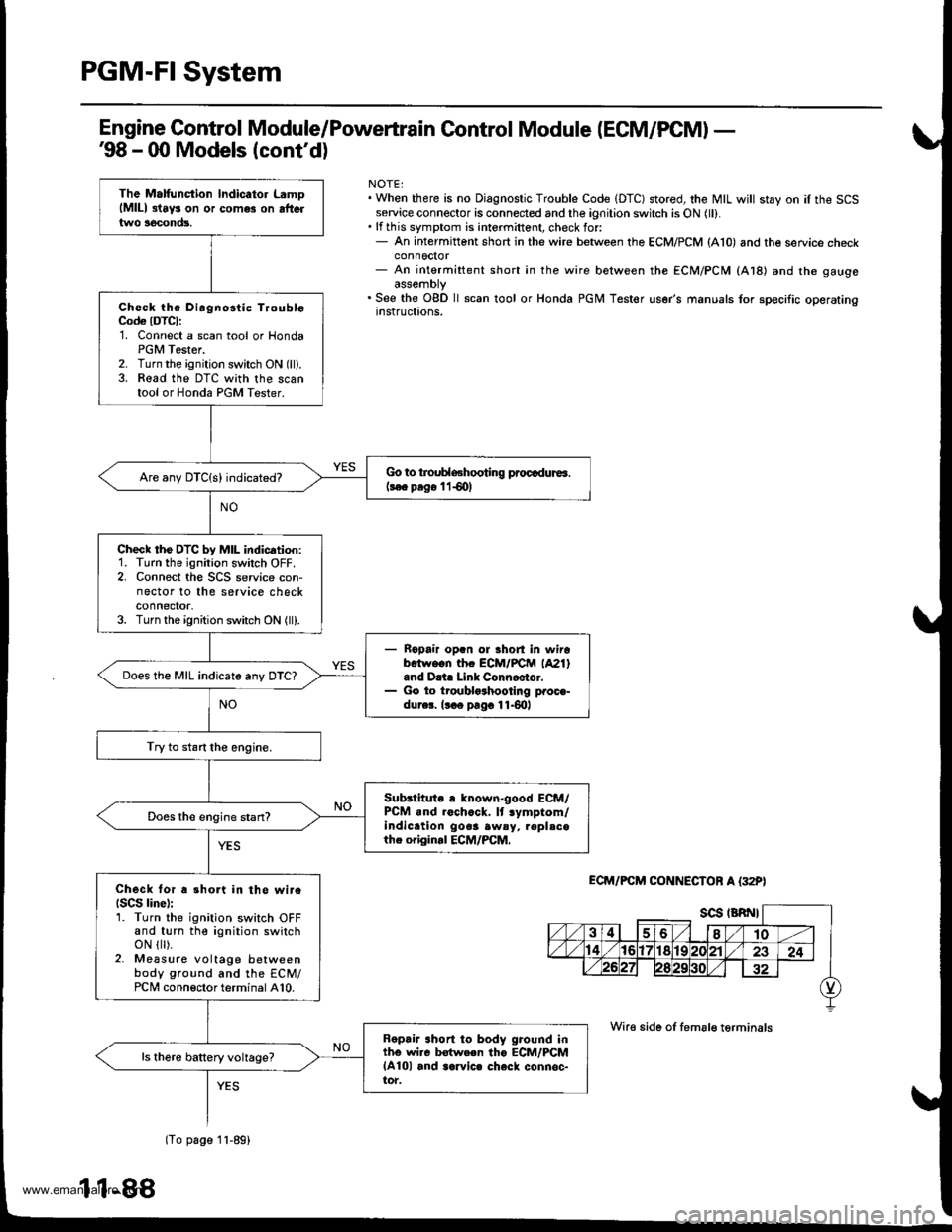
PGM-FI System
Engine Control Module/Poweftrain Control Module (ECM/PCM) -'98 - 00 Models (cont'dl
NOTE:. When there is no Diagnostic Trouble Code IDTC) stored, the MIL will stay on iI the SCSservice connector is connected and the ignition switch is ON (ll).. lf this symptom is intermittent, check for:- An intermittent short in the wire between the ECM/PCM (A10) and the service checkconnoctor- An intermittent short in the wire between the ECM/PCM (At8l and the gaugeassemDty. See the OgD ll scan tool or Honda PGM Tester user's manuals for specific operatingrnstructions.
ECM/FCM CONNECTOF A {32P)
Wire side of femsle t6rminals
The Malfunction lndicator LamolMlll 3lays on or comes on aftertwo 3econds.
Check the Dirgnostic TroubloCod€ (DTCI:'1. Connect a scan tool or HondaPGM Tester.2. Turn the ignition switch ON (ll).3. Read the DTC with the scantool or Honda PGM Tester.
Go to troublGhooting procadura.(3€c prg€ l lS0l
check tho DTc by MIL indication:1. Turn the ignition switch OFF.2. Connect the SCS service con-nector to the service checkconnector,3. Turn the ignition switch ON (ll).
Ropair op.n ol Bhort in wirob.twe.n thc ECM/FCtrl (A21)
and D.i. Link Connoctor.Go to troublo3hootlng proc€-dur6. lt o pag. 11.6lrl
Does the MIL indicate any DTC?
Try to start the engine.
Sub3titute r known"good ECM/PCM .nd roch.ck. lt .ymptom/indic.tion gooa awsy, repl.cothe origin.l ECM/PCM.
Does the engine stan?
Check tor a 3hort in the wireISCS linel:1. Turn the ignition switch OFFand turn the ignition switchoN { ).2- Measure voltage betweenbody ground and the ECM/PCi, conneclor terminal A10.
Ropria ahort to body ground intho wi.c Mwe.n tho ECM/PCMlA10l and aarvic. check connsc-tor.
lTo page 1l-89)
11-88
www.emanualpro.com
Page 297 of 1395
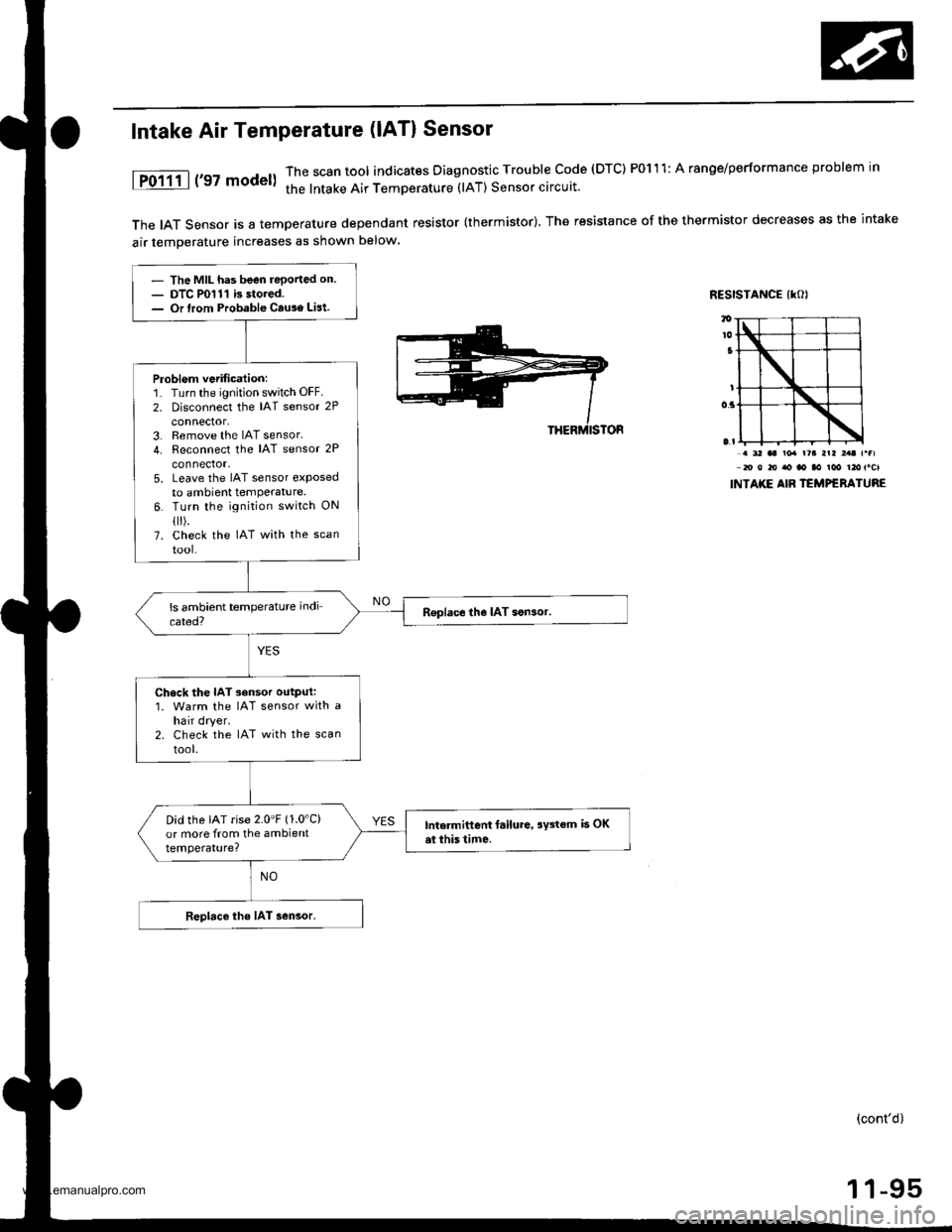
The IAT Sensor is a temperature dependant resistor (thermistor). The resistance of the thermistor decreases as the intake
air temDerature increases as shown below
RESISTANCE IKOI
Intake Air Temperature (lAT) Sensor
1P0111 | ('97 model)The scan tool indicates Diagnostic Trouble code (DTC) P0111: A ranoe/performance problem in
the lntake Air TemDerature (lAT) Sensor circuit.
. 3' aa ro. r?a arl ,.t r.fl20 0 to ao ao aa ioo t2otocl
INTAKE AIB TEMPERATURE
- The MIL has been reported on.- DTC P0111 is stored.- Or lrom Probable Cause List.
Problem vetification:1. Turn the ignition switch OFF.
2. Disconnect the IAT sensor 2P
connector,3. Remove the IAT sensor.4. Reconnect the IAT sensor 2P
connector,5. Leave the IAT sensor etposedto ambient temPerature.6. Turn the ignition switch ON
flr).7. check the IAT with the scan
tool-
R€place the IAT son3or.
Check the IAT sensor output:1. Warm the IAT sensor with ahair dryer.2. Check the IAT with the scan
tool.
Did the IAT rise 2.0'F (1.0'C)
or more from the ambienttemperature?
Intermittent f.ilure, aY3tem is OKai this tim6.
Replace the IAT sensor.
(cont'd)
1 1-95
www.emanualpro.com
Page 319 of 1395
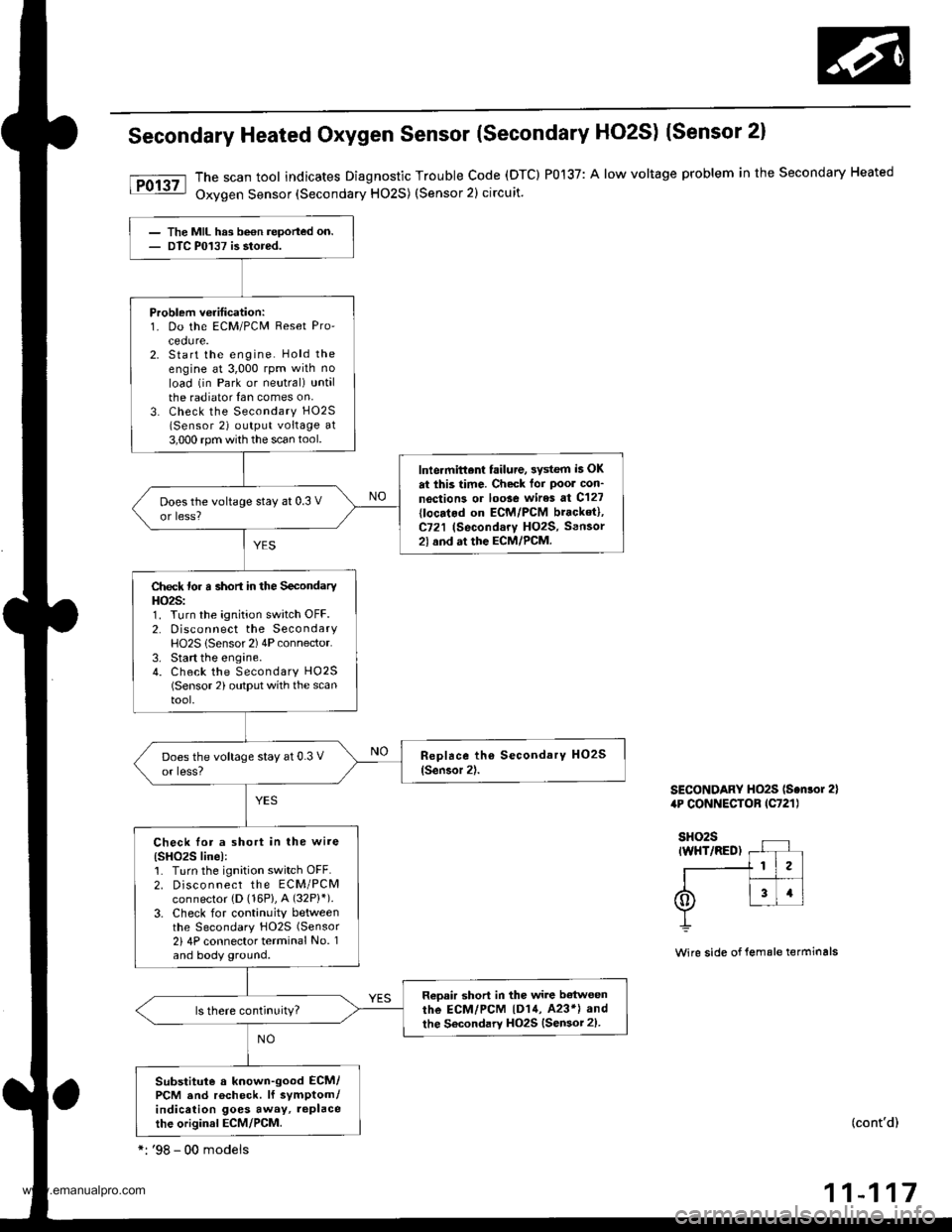
Secondary Heated Oxygen Sensor (Secondary HO2S) (Sensor 2)
The scan tool indicates Diagnostic Trouble code (DTC) P0137: A low voltage problem in the secondary Heated
Oxygen Sensor (Secondary HO2S) (Sensor 2) circuit.
SECONDARY HO2S ls.nlor 2)4P CONNECTOB lC721l
Wire side of lemale terminals
(cont'd)
11-117
The MIL hrs been reported on.DTC P0137 is stored.
Problem veritication:1. Do the ECM/PCM Reset Pro'cedure.2. Start the engine. Hold theengine at 3,000 rpm wilh no
load (in Park or neutral) untalthe radiator {an comes on,3. Check the Secondary H02S
lSensor 2) output voltage at3,000 rpm with the scan tool.
lnlermittent failure, 3ystem i5 OK
at this time. Check tor Poor con'
noction3 or loose wires at C127
{locatod on ECM/PCM bracket},C721 (Secondary HO2S, Sensor2l and at the ECM/PCM.
Does the voltage stay at 0.3 V
or less?
Check for a short in the SecondaryHO2S:1. Turn the ignition switch OFF.2. Disconnect the SecondaryHO2S lSensor 2) 4P connector.3. Start the engine.4. Check the Secondary HO25(Sensor 2) output with the scantool.
Check lor a short in the wire(SHO2S linel:1. Turn the ignition switch OFF.2. Disco n nect the ECM/PCMconnector {D (16P}, A (32P}').
3. Check for continuity betweenthe Secondary HO2S (Sensor
2i 4P connector terminal No. 1and body ground.
Reoair short in the wire b€twoen
rhe ECM/PCM |D14, 423*l and
the Secondary HO2S {Sensor 2).
Substitute a known-good ECM/PCM and rocheck. lf symptom/indication goes away, replacethe original ECM/PCM.
*: '98 - 00 modeis
www.emanualpro.com
Page 320 of 1395
PGM-FI System
Secondary Heated Oxygen Sensor (Secondary HO2SI (Sensor 2l (cont'dl
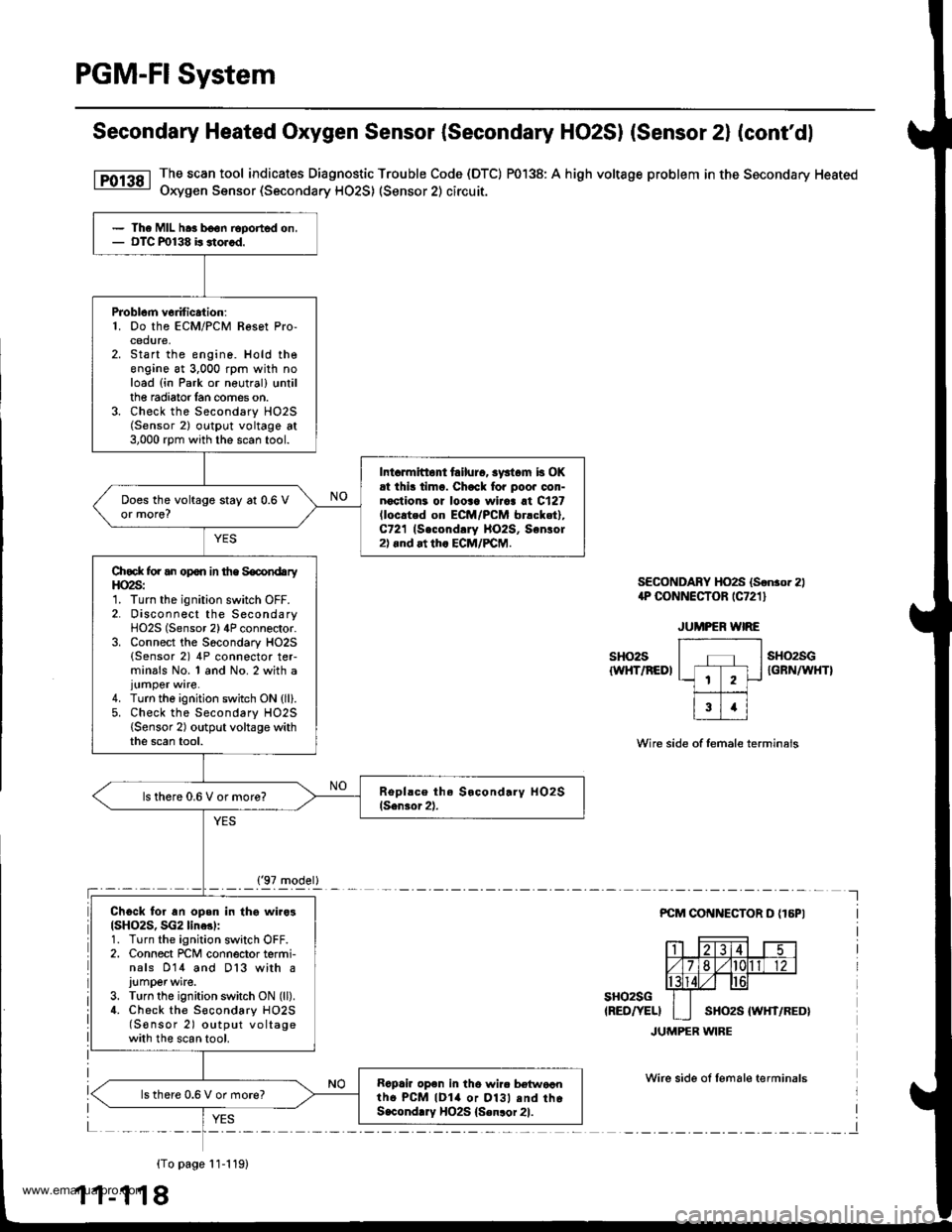
The scan tool indicates Diagnostic Trouble Code (DTC) P0138: A high voltage problem in the Secondary Heated
Oxygen Sensor (Secondary HO2S) (Sensor 2) circuit.
SECONDABY HO2S (Sonror 2)1P CONNECTOR rC721 l
sHo2s{WHT/REDI
sH()2sGIGFN/WHTI
Wire side of female terminals
PCM COI{NECTOR D {16PI
sHo2sG(RED/YELI
JUMPER WIRE
Wirc side ol lemale terminals
{To page 11-119)
1 1-1 18
The MIL hra b€on Eported on,OTC m138 b stor.d.
PJoblcm v6dtic.tion:1. Do the ECM/PCM Resot Pro-cedure,Start the engine. Hold theengine at 3,000 rpm with noload (in Park or neutral) trntilthe radiator lan comes on.Check the Secondary HO2S(Sensor 2) outpl.rt voltage at3,000 rpm with the scan tool.
Int.rmitto tailurc, syst.m b OKrt ihi! timo. Chack fo. poo. oon-noctioni or looaa wiiaa at C127lloc.ted on EcM/PcM br.cket),C721 (Second!ry llO2S, Sonlol2).nd at th. ECM/PCM.
Does the voltage stay at 0.6 Vor more?
Chock for an opon in the SocondaryHO2S:1. Turn the ignition switch OFF.2. Disconnect the SecondaryHO2S (Sensor 2) 4P connector.3. Connect the Socondary HO2S(Sensor 2) 4P connector ter-minals No. 1 and No. 2 with a
4. Turn the ignition switch ON {ll}.5. Check the Secondary HO2S{Sensor 2) output voltage withthe scan tool.
ls there 0.6 V or more?
Ch6ck for an open in thg wiro3(SH()2S, SG2 line3l:1. Turn the ignition switch OFF.2. Connect rcM connector termi-nals 014 and D13 with a
J!mper wite.3. Turn the ignition switch ON (ll).
4. Check the S€condary HO2S(S€nsor 2) output voltagewith the scan tool.
Rapair op6n in tho wir. b€{woantho PcM lDla or Dl3l .nd thoS.condlry HO2S {Senlor 21.
lsthere 0.6 V or more?
('97 model)
www.emanualpro.com
Page 321 of 1395
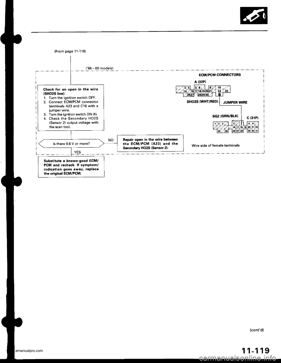
(From page 11-118)
Check for an open in tha wire
ISH()2S linel:1. Turn th€ ignition switch OFF.2. Connect ECM/PCM connectorterminals A23 and C18 with a
iumper ware.3. Turn the ignition switch ON (ll).
4. Check the Secondary HO2S(Sensor 2) output voltage withthe scan tool.
Repair opon in tho wire botwaenthe ECM/PCM lA23l and theSecond.ry HO2S (Sonsot 21.ls there 0.6 V or more?
Substitute a known.good ECM/PCM .nd recheck. It symptom/indication goes rway, replace
the origin.l ECM/PCM.
('98 - 00 models)
ECM/PCM CONNECTORS
A l32Pl
Wire side of fomale terminals
L _._._ _ _I
SHO2S W}iT/RED) | JUMpER W;RE
(cont'd)
1 1-1 19
www.emanualpro.com
Page 323 of 1395
Heated Oxygen Sensor (HO2S| Heater
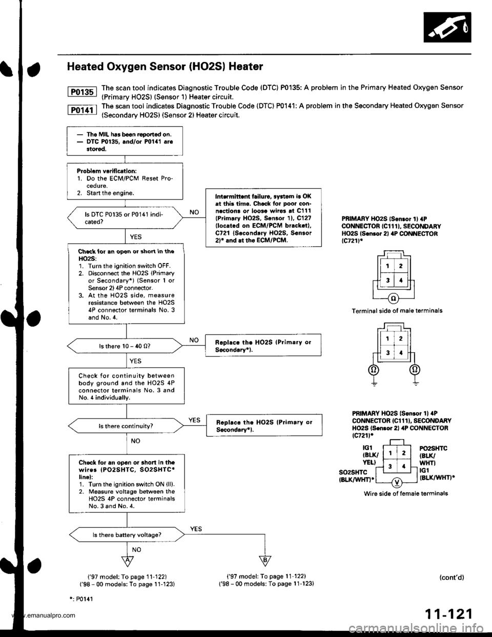
The scan tool indicatos Diagnostic Trouble Code (DTC) P0135: A problem in the Primary Heated Oxygen Sensor
{Primarv HO2S) (Sensor 1) Heater circuit.
The scan tool indicates Diagnostic Trouble Code (DTC) P0141: A problem in the Secondary Heated Oxygen Sensor
(Secondary HO2S) (Sensor 2) Heater circuit.
Fol3sl
Fo11tl
PBIMARY HO2S ls.n.or ll 4PCONNECTOR (CI 1 1 I, SECONDARYHO2S ls.n.o.2l aP CONNECTORlc721l.
Terminal side of male t€rminals
PRIMARY HO2S lson.o. 1l aPCONNECTOR {Cl 1 1 }, SECONDARYHO2S ls.nror 21 4P CONNECTORtcr21l.
so2sHTctBLK/WHn.
PO2SHTC(BLK/
WHTItGlIBLKAAIHTI'
Wire sid€ of lemale terminals
('97 model: To page '11-122)
('98 - 00 models: To page 11-'123)
*: P0141
('97 model: To page'11-122)
1'98 - 00 modelsl To page 11-123)(cont'd)
11-121
- Th6 MIL h.. bocn roponod on.- DTC P0135, and/oi mlal arestored.
Probl.m verification:1. Do the ECM/PCM Resot Pro-cedure,2. Start the engine.Int.rrnittaii frilurc, awtom ir OKat thi3 time. Chock lor poor con-n.ctiona or loosa wiro3 !t C111
lPrim.ry HO2S, Sen3o. 11. C12?llocatcd on ECM/PCM br.ck.t),C721 lsocond.ry Ho2s, s.n3or2r and at tho ECM/PCM.
Ch.ck ior an opon or shoYt in theHO2S:1. Turn the ignition switch OFF.2. Disconnoct the Ho2s (Primary
or Secondary*) (Sensor 1 orSensor 2)4P conneclor.3. At the HO2S side, measureresistance between the HO2S4P connector terminals No. 3and No.4.
ls there 10 - 40 0?
Check for continuity betweenbody ground and the HO2S 4Pconnector terminals No. 3 andNo. 4 individually.
Check tor an op6n or 3hort in thewires IPO2SHTC, SO2SHTC'linel:1. Turn the ignition swhch ON {ll).2. Moasure voltage between theHO2S 4P connector terminalsNo.3 and No.4.
www.emanualpro.com
Page 324 of 1395
PGM-FI System
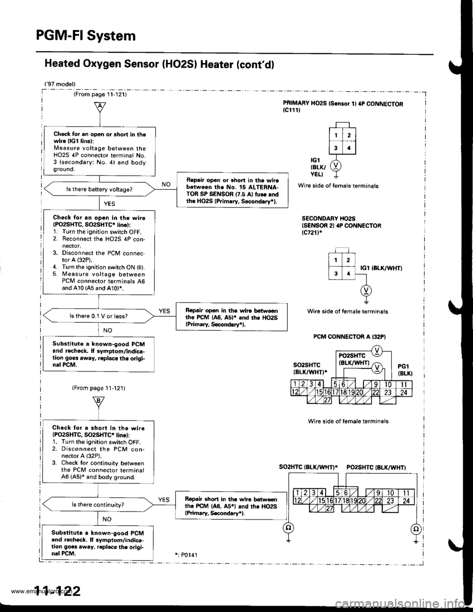
Heated Oxygen Sensor IHO2S) Heater (cont'd)
{'97 model)
(From page l1-121)
PRIMARY HO2S (S.nsor 1) ap CONNECTOR{cl111
| 112 ||.�i-l
13 .l
'ot X-tErK/ (9YELI -L
Wire side of female terminals
SECONDARY HO2SISENSOR 21 4P CONNECTORlcr21l,
IGl IBLK/WHTI
Wire side ol female terminals
Wire side of female terminals
So2HTCIALK/WHTI* PO2SHTCIBLK/WHTI
Chock for en open or lhort in thewire (lG1 line):Measure voltage between theHO2S 4P connector terminal No.3 (secondary: No. 4) and bodyground,
Reprir op6n or 3hort in thc wircbetwo.n th€ No. 15 ALTERNA-TOR SP SENSOR (7.5 Al fu!. rndtho HO2S (Primary. Socond.ry*).
Ch€ck for an open in the wire(PO2SHTC, SO2SHTC. lin€):1. Turn the ignition switch OFF.2. Reconnect the HO2S 4P con-
3. Disconnect the PCM connec-tor A (32P).4. Turn the ignition switch ON (ll).5. Measure voltage betweenPCM connector t€rminals 46and A10 (A5 and A10)*.
Bepair opon in the wiro botwoonthe PcM (A6. A5lr and tho Ho2s{Prim.ry, Socond!ryr}.
ls thero 0.1 V or less?
Substitute a lnown-good PCMand recheck. lt 3ymptom/indica-tion goes away, .oplaco the origi-nal PCM.
Check fo. a ahort in the wireIPO2SHTC, SO2SHTC. lins):1. Turn the ignirion switch OFF.2. Disconnect the PCM con-nector A {32P).3. Check lor continuily betweenthe PCM connector terminal46 (A5)* and body ground.
Bopair short in the wire lrotwsentho PC{r4 {A6, A5rl and the HO2SlPiimary, S€condary.l.
Substitute a known-good PCMand .echgck. lf 3ymptom/indica-tion go€s awry. repl.cethe origi-nal PCM.
11-122
www.emanualpro.com
Page 325 of 1395
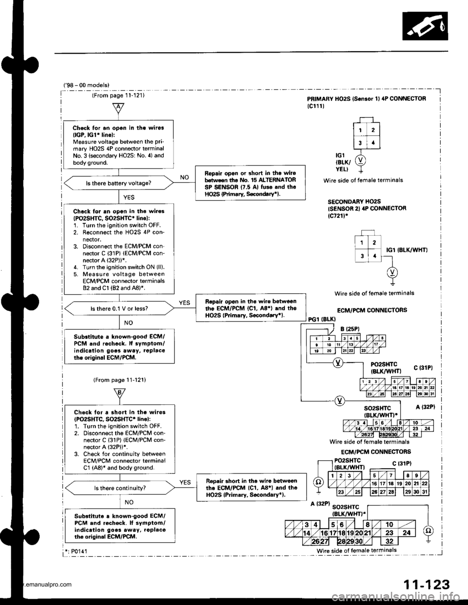
Check for an open in the witoa(lGP,lGl'lino):
Mgasure voitage between the pri-
mary HO2S 4P connector terminalNo. 3 (secondary HO2S: No. 4) andbody ground.
Bepair opan or short in tho wilobdtween th6 nlo. 15 ALTERNATORSP SENSOR 17.5 Al fu$ .nd th6HO2S {Primrry, S€condtrytl.
Chock lor sn opon in the wires
IPO2SHTC, SO2SHTC' lincl:1. Turn the ignition switch OFF.2. Reconnect the HO2S 4P con-nector.3. Disconnect the ECM/PCM con-nector C (31P) (ECM/PCM con-neaor A (32P))*.
4. Turn the ignition switch ON (ll).
5. Moasure voltage betweenECM/PCM connector terminals82 and Cl (82 and A8)*.
Repsir opsn in tha wire betweentho ECM/PCM (C1, A8.) .nd theHO2S lPrimsry, Socond.ry*}.ls there 0.1 V or less?
Sub.titute a known-good ECM/PCM and rocheck. lf iymptom/indicrtion goes away, repbcethe original ECM/PCM.
('98 - 00 models)
Wire side of female terminals
ECM/FCM CONNECTORS
IGl IBLK/WHT}
PRIMARY HO2S {S.n3or 1l aP CONNECTOR
lc111l
11 2l
r--T -l3t.lL-.IJ------J
lcl /5'tErK/ g,YELI I
Wire side of female terminals
SECONDARY HO2S
{SENSOR 2} 4P CONNECTOR(c7211'
PGl (BLK}
lFrom page 11-12'!)
Chock lor a short in the wi.es(PO2SHTC, SO2SHTC' linol:1. Turn the ignition switch OFF.2. Disconnect the EcM/PcM con-nector C {31P) lECM/PCM con-nector A (32P))*.
3. Check for continuity betweenECM/PCM connector terminalCl (A8)* and body ground.
Roolir 3hort in th. wiro betwoonthe ECM/PCM lC1, A8'l and theHO2S (Primary, S6condary*).ls there continuity?
Sub3tituie s known-good ECM/PCM and rech6ck. It symptom/indicaiion goes away. lgplacoth6 origin.l ECM/PCM.
Wire side of lemale terminals: P0'14'l
11-123
www.emanualpro.com
Page 326 of 1395
PGM-FI System
Fuel Supply System
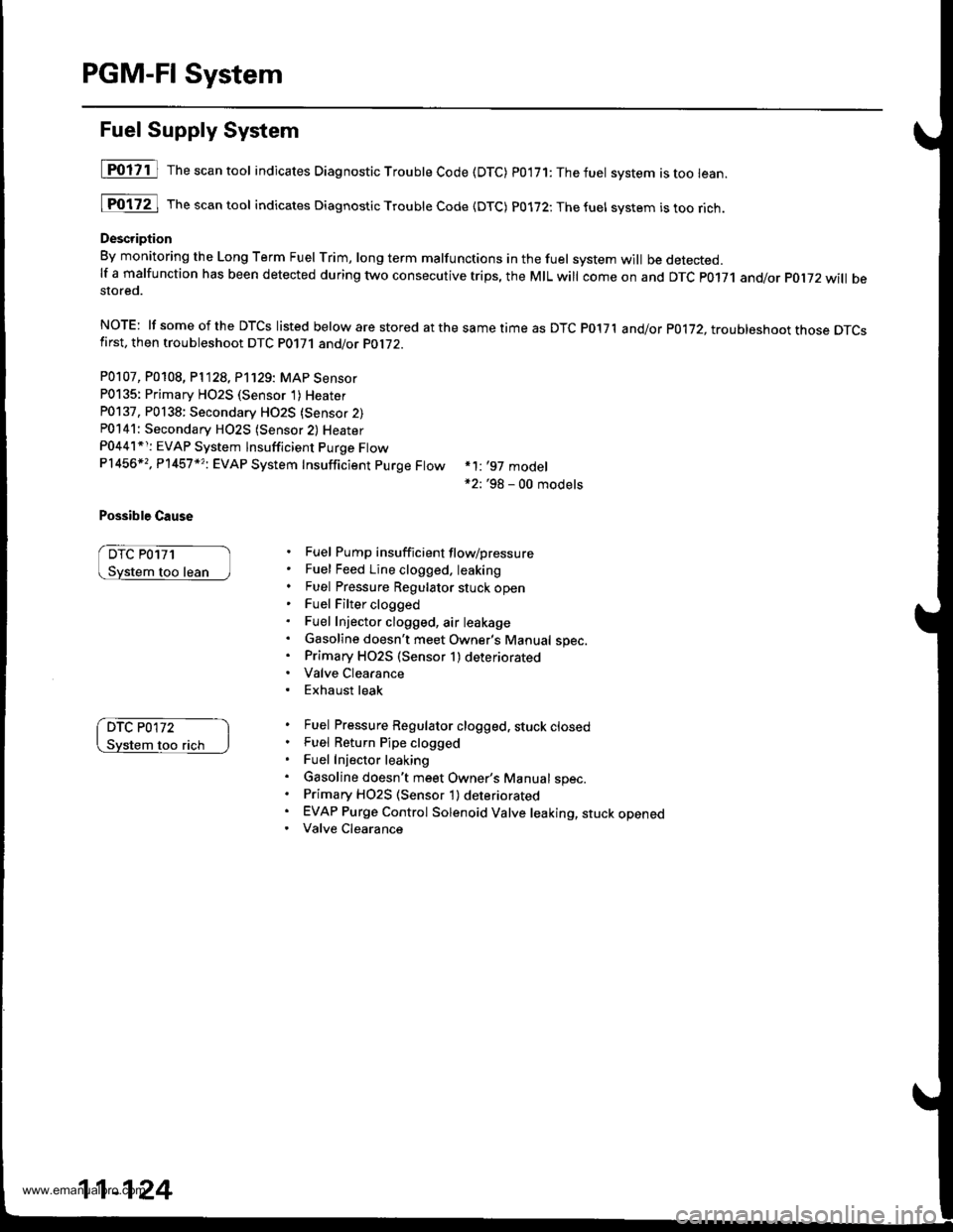
[POliil The"""ntool indicates Diagnostic Troubte Code (DTC) p0'171:Thefuet system istoo lean.
[Fo17ZJ rh""""ntool indicates Diagnostic Troubte code {DTc) p0172:Thefuel svstem istoorich.
Description
By monitoring the Long Term Fuel rrim, long term malfunctions in the fuel system will be detected.lf a malfunction has been detected during two consecutive trips, the MIL will come on and DTc p0171 and/or pol72 will bestored.
NOTE: lf someof the DTCS listed below are stored atthesametimeas DTC P017'l and/or p0172, troubleshoot those DTcsfirst, then troubleshoot DTC P0171 and/or PO1i2.
P0107, P0108, P1128, P'1129: MAP Sensor
P0135: Primary HO2S (Sensor 1)Heater
P0137, P0138: Secondary HO2S {Sensor 2)P0141: Secondary H02S (Sensor 2) Heater
P0441*r: EVAP System lnsufficient Purge FtowP1456*,, P'l457 *?i EVAP System Insufficient purge Ftow
Possible Cause
DTC P0171
too lean
*1: '97 model*2: '98 - 00 models
Fuel Pump insufficient flow/pressure
Fuel Feed Line clogged. leaking
Fuel Pressure Regulator stuck openFuel Filter clogged
Fuel Injector clogged, air leakage
Gasoline doesn't meet Owner's Manual spec.Primary HO2S (Sensor 1) deteriorated
Valve Clearance
Exhaust leak
Fuel Pressure Regulator clogged, stuck closedFuel Return Pipe clogged
Fuel Injector leaking
Gasoline doesn't meet Owner's Manual spec.Primary H02S (Sensor 1) deteriorated
EVAP Purge Control Solenoid Valve leaking, stuck openedValve Clearance
DTC P0172
flch
11-124
www.emanualpro.com