Throttle HONDA CR-V 2000 RD1-RD3 / 1.G Owner's Guide
[x] Cancel search | Manufacturer: HONDA, Model Year: 2000, Model line: CR-V, Model: HONDA CR-V 2000 RD1-RD3 / 1.GPages: 1395, PDF Size: 35.62 MB
Page 312 of 1395
PGM-FI System
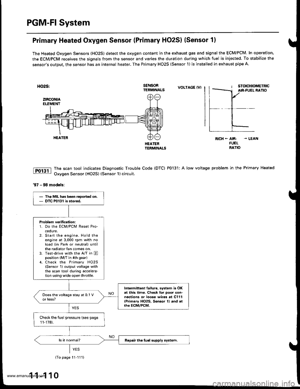
Primary Heated Oxygen Sensor (Primary HO2S) (Sensor 1)
The Heated Oxygen Sensors (HO2S) detect the oxygen content in the exhaust gas and signal the ECM/PCM. In operation,
the ECM/PCM receives the signals from the sensor and varies the duration during which fuel is iniected. To stabilize the
sensor's output, the sensor has an internal heater. The Primary HO2S (Sensor 1) is installed in exhaust pipe A.
HO2S:
ztRcoNtAEI.IMENT
s€NsoRTERMINALSVOLTAGE IVI
HEATEBTERMINALS
The scan tool indicates Diagnostic Trouble Code (DTC) P0131: A low voltage
Oxygen Sensor (HO2S) {Sensor 1} circuit,
RICH - AIR. . LEANFUELNATO
problem in the Primary Heated
37 - 98 models:
HEATER
The MIL has been reoorted on.DTC P0131 is stoied.
Problem verification:1. Do the ECM/PCM Reset Pro-ceoure.Start the engine. Hold theengine at 3,000 rpm with noload (in Park or neutral) untilthe radiator fan comes on.Test-drive with the A/T in Eposition (M/T in 4th gear)Check the Primary HO2S{Sensor 1} output voltage withthe scan tool during accelera-tion using wide open throttle.
Intermittent f.ilure, system is OKat this time. Check fo. poor con-nections or loose wirer at C111(Primary HO2S, SeGor 1) and atrh€ ECM/FCM.
Check the fuel pressure (see page
11-178).
Repair the fuel supply system.
{To page 11'111}
1 1-1 10
www.emanualpro.com
Page 314 of 1395
PGM-FI System
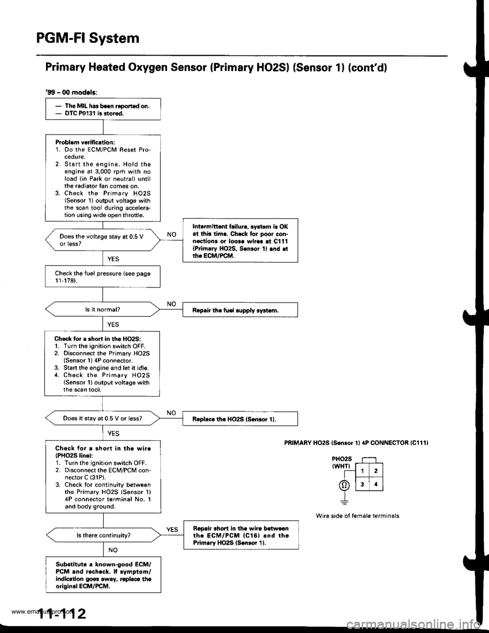
'99 - 00 models:
- The MIL has bsen reported on.- DTC P0131 ir storod.
Problem ve fication:1. Do the ECM/PCM Reset Pro-cedure,2. Start the engine. Hold theengine at 3,000 rpm with noload {in Park or neutral) untillhe radiator tan comes on.3. Check the Primary HO2S(Sensor 1) oltput voltage withthe scan tool during accelera-tion using wide op€n throttle.
Inl.rmittant failura, 3yrtam i! OKat thb tim.. Ch.ck tor poor con-nectiona oa looaa wlraa al C111{Pri|n.ry HO2S, Son3or 1l .nd .ttho ECM/FCM,
Does the voltage stay at 0.5 Vor less?
Check tho fuel pressure (see pago1r,178).
R.p.ir th. fu€l lupply ry!t.m.
Chock lor a short in tho HO2S:1. Turn the ignition switch OFF.2. Disconnect the Primary HO2S(Sensor 1) 4P connector.3. St6rt the engine and lot it idle.4. Check the Primary HO2S(Sensor 1) output voltage withthe scan tool,
Does it stay 6t 0.5 V or less?Rephc. th6 HO2S (S.n3or 11.
Chock for a short in tho wirc(PHO2S lino):1. Turn the ignition switch OFF.2. Disconnect the ECM/PCM con-nector C (31P).
3. Check tor continlity betweenthe Primary HO2S {Sensor 'l}
4P connector terminal No. Iand body ground.
Ragah rhort in tha wira balwoanth. ECM/PCM {Cl61 rnd thcPrirn.ry HO2S (S.n3or 11.
Substltut6 a known-good ECM/PCM and recheck. lf rymptom/indicrtion 00os away, raplaco thcoriginal ECM/PCM.
Primary Heated Oxygen Sensor (Primary HO2SI (Sensor 1l (cont'd)
PRIMARY HO2S (Son.or 1l aP CONNECTOR |C111)
PHO2S T--1rwHTr f-T---]
--1 1 2lI t--- 1t6)lslrlv L__r__J
_L
Wire side ol female terminals
11-112
www.emanualpro.com
Page 315 of 1395
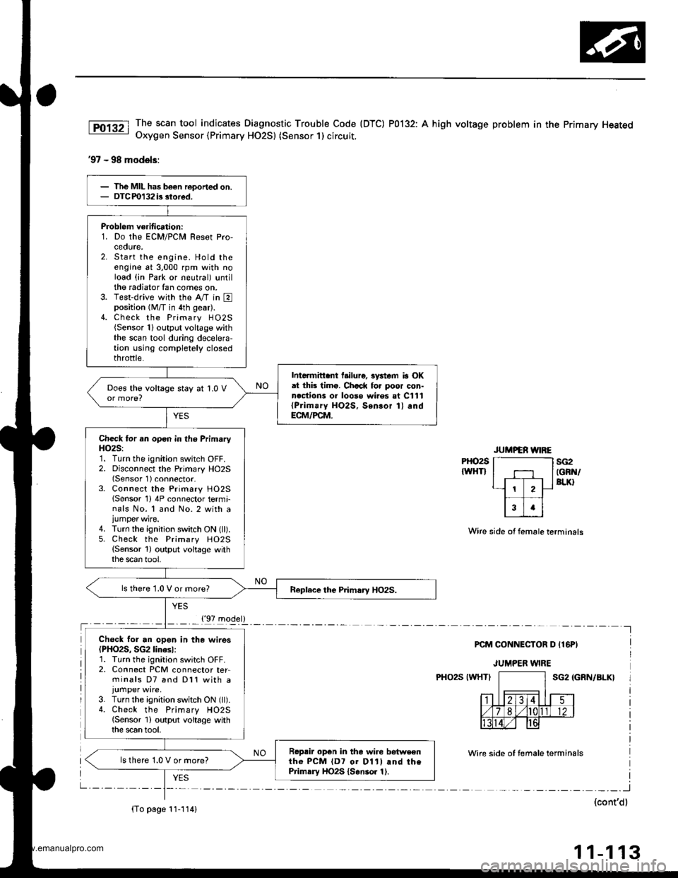
The scan tool indicates Diagnostic Trouble Code (DTC) P0132: A high voltage problem in the Primary HeatedOxygen Sensor {Primary HO2S) (Sensor 1) circuit.
'97 - 98 models:
PHO2S
IWHTIsG2IGRN/BLK}
Wire side ot female terminals
PCM CONNECTOR D {16PI
JUMPER WIRE
PHO2S IWHTISG2 IGRN/BLK}
Wire side of temale terminals
I
(cont'dl
11-113
Problem verification:1. Do the ECM/PCM Resot Pro,ceoute,2. Start the engine. Hold theengine at 3,000 rpm with noload (in Park or neutral) untilthe radiator fan comes on.3. Test-drive with the Ay'T in Eposition (M/T in 4th gear).4. Check the Primary H02S{Sensor 1}output voltage withthe scan tool during decelera-tion using completely closedthrottle.
Intormittent l.ilure, 3ystem ia OKat thb timo. Chcck fo. poor con-nections 01 looso wi.es at C111{Prim!ry HO2S, Sensor 1} andECM/PCM.
Does the voltage stay at 1.0 V
Check for an open in th6 PrimaryH()2S:1. Turn the ignition switch OFF.2. Disconnect the Primary HO2S(Sensor 1) connector-3. Connect the Primary HO25lSensor 1) 4P connector termi-nals No. 1 and No. 2 with ajumper wire.4. Turn the ignition switch ON (ll).5. Check the Primary HO2S(Sensor 1) output voltage withthe scan tool,
ls there 1.0 V or more?
Ch€ck for an opon in the wires(PHO2S, SG2linesl:1. Turn the ignition switch OFF.2. Connect PCM connector ter-minals D7 and Dl1 with a
3. Turn the ignition switch ON (ll).4. Check the Primary HO2S{Sensor 1) output voltage withthe scan tool.
Roprir opon in the wire betweontho PCM {D7 01 D11l and thePrimsry HO2S {S6nsor 1).
ls there 1.0 V or more?
{'97 model}
{To page 11-114)
www.emanualpro.com
Page 339 of 1395
Barometric Pressure (BARO) Sensor
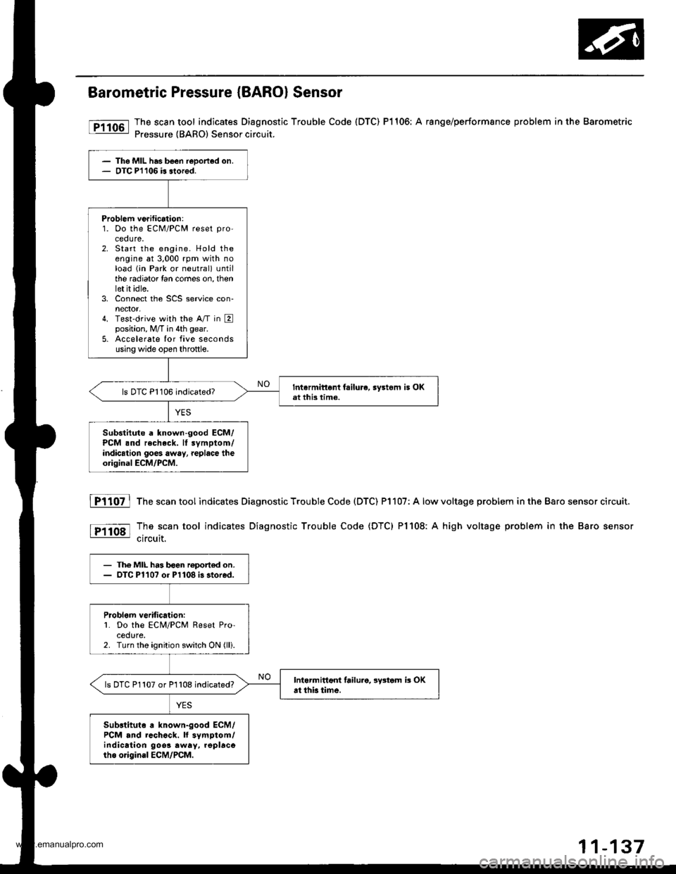
The scan tool indicates Diagnostic Trouble Code (DTC) P1106: A range/performsnce problem in the Barometric
Pressure {BARO) Sensor circuit.
The MIL has been reDorted on.OTC Pl106 b slored.
Problem ve.ification:1. Oo the ECM/PCM reset pro'
ceoure.2. Start the engine. Hold theengine at 3,000 rpm with noload (;n Park or neutral) untilthe radiator lan comes on, thenlet it idle.3. Connect the SCS service con-nector,4. Test'drive with the A/T in Eposition, M/T in 4th gear.
5. Accelerate Ior five secondsusing wide open throttle.
Intermittent fsilure, sy3tom i5 OKat this time.ls DTC P1106 indicated?
Substitute a known-good ECM/PCM .nd recheck. It symptom/indication goes away, replace theorigioal ECM/PCM.
fTiloz l
tP11o8l
The scan tool indicates Diagnostic Trouble Code (DTC) P1107: A low
The scan tool indicates Diagnostic Trouble Code (DTC) Pl108: A
circuit.
voltage problem in the Baro sensor circuit.
high voltage problem in the Baro sensor
- The MIL h.3 b€en roport€d on.- OTC Pl10? or Pl108 i3 stored.
Problom veritic.lion:L Do the ECM/PCM Reset Pro-cedure.2. Turn the ignition switch ON (lli.
Intarmittoni failure, lystom b OKat thb time.ls DTC P1107 or P1108 indicated?
Sub3tituto a known-good ECM/PCM and rcch6ck. ll symptom/indication 9oo3 away. .oplacorho o.igin.l ECM/PCM.
www.emanualpro.com
Page 352 of 1395

ldle Control System
ldle Control System
I P0505 | The scan tool indicates Diagnostic T.ouble Code (DTCI PO5O5: ldlecontrol svstem mattunction.
NOTE: lf DTC P1508 is stored at the same time as DTC P0505, troubleshoot DTC P1508 first. then troubleshoot DTC p0505.
Possibls Cause
. IAC valve mechanical malfunction. Throttle body clogged port, improper adlustment. Intake manifold gasket leakaging. Intake air hose loose leakaging. Vacuum hose leakaging
a ECT sensor incorrect output. Throttle Position sensor incorrect output
Troubleshooting Flowchart
The MIL has been reDorted on.DTC P0505 is sto.ed.
Problem verificationi1. Start the engine. Hold theengine at 3,000 rpm with noload (in Park or neutral) untilthe radiator Ian comes on, thenlet it idle.2. With the scan tool, check thelollowing items.- Throttle position should beapprox. 10% with the throt-tle {ully closed.- Engine coolant temperature shorJld be 194 - 205'F(90 - 96"C).lf they are not within thespec., repair the faulty sen-sor circuit.3 Check the engine speed atidle with no-load conditions:headlights, blower fan. reardefogger, radiator lan, and airconditioner are not operaling,
Inte.mittent failure. syltem is OKat this time.ls it 750 {730)* i 50 rpm?
ls il 700 (680)' rpm or less?
{To page 11-151)(To page 1'l-151)
l:'99 - 00 models
www.emanualpro.com
Page 353 of 1395
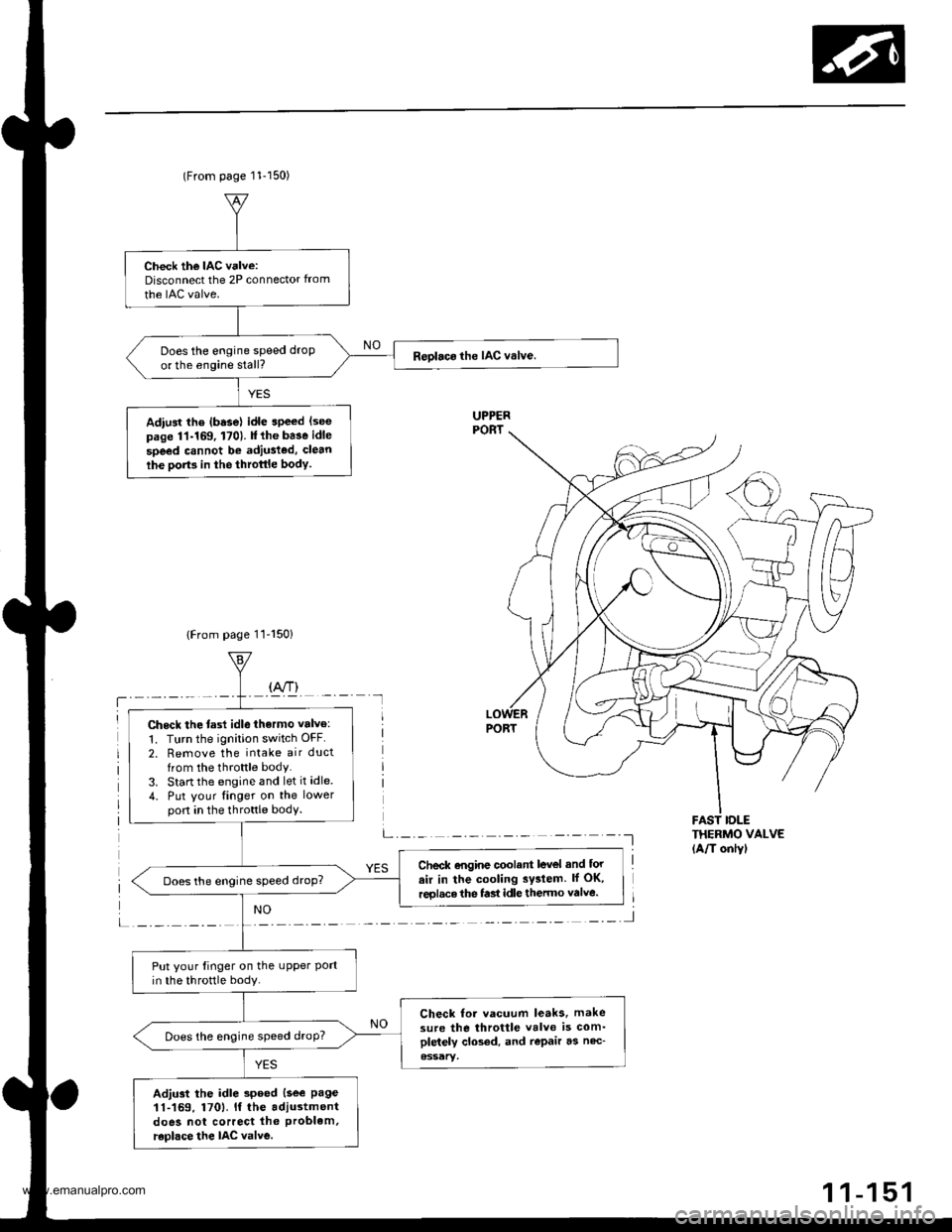
(From page 11-150)
{From page 11-150}
THERMO VALVE(A/T onlyl
Check the IAC valve:Disconnect the 2P connector from
the IAC valve.
Does the engine speed droP
or the engine stall?
Adiust the (basel idl€ speed lseepage 11-169, 1t0). Itihe ba3e idle
speed cannot be adiust€d, clean
the Dorts in the throttle body.
UPPER
Check the tast idle lhermo valve:
1. Turn the ignition switch OFF.
2. Remove the intake air ductfrom the throttle body.3. Start the engine and let it idle.
4. Put your finger on the lowerpon in the throttle body.
Check engine cool.nt level and for
air in the cooling sy3lem. lf OK,
reolace the f.st idle thermo valve.Does the engine speed drop?
Put your Iinger on the uPPer Portin the throttle body.
Check for vacuum leaks, make
sure the throttle valve is com'pletely clo3ed. and repair as nec-Does the engine speed droP?
Adjust the idle spoed lsee Page11-169. 1701. lf the adiustmentdoes not correct lhe problem,
r.olace the IAC valve.
www.emanualpro.com
Page 354 of 1395
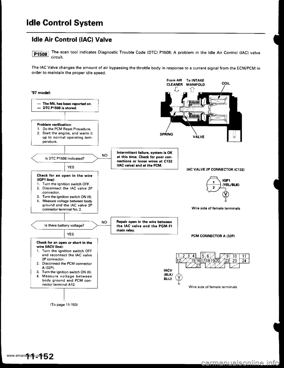
ldle Control System
ldle Air Control llAC) Valve
The scan tool indicates Diagnostic Trouble Code (DTC) Pl508: A probtem in the ldle Air Controt flAC) varvecircuit.
The IAC Valve changes the amount of air bypassing the throttle body in response to a current signal from the ECM/PCM inorder to maintain the proper idle speed.
37 model;
IAC VALVE 2P CONNECTOR {C132}
,f rcp'# IYEL/BI.(II2f-1-d)
Y
Wir€ side of female terminals
PCM CONNECTOR A I32PI
tacvIBLK/BLU)
From AIR To INTAKECLEANER MANIFOLD
Wire side of female terminals
The MIL has beon .eport€d on.OIC Pl508 is sto.ed.
Problem veiification:1. Do the PCM Reset Procedure.2. Start the engine, and warm itup to normal operating tem-perature.
Inte.mittent failure, systcm b OKat thi3 time. Check tor poo. con-nections or loose wircs at C132(lAC v.lvel and at the PCM.
ls DTC Pl508 indicated?
Check lor an open in the wir6{lGPl lins}:1. Turn the ignition switch OFF.2. Disconnect the IAC valve 2Pconnector.3. Turn the ignition switch ON {ll).4. Measure voltage between bodyground and the IAC valve 2Pconnector term inal No.2.
Repair open in the wire trctwoontha IAC v!lv6 and the PGM-Flmain relly.
Chock for an opan o. short in thowi.e (lACv linel:1. Turn the ignition switch OFFand reconnect the IAC valve2P connector.2. Disconnect the PCM conneclorA (32P).
3. Turn the ignition switch ON {ll).4, Measure voltage betweenbody ground and PCM con-nector terminal A12.
{To page 1l-153)
www.emanualpro.com
Page 370 of 1395
ldle Control System
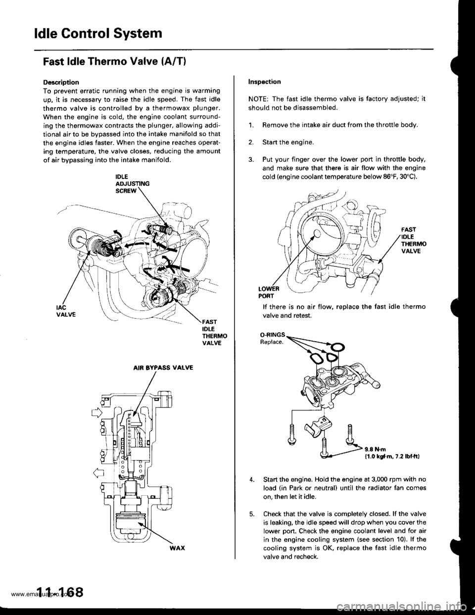
Fast ldle Thermo Valve lA/T)
Description
To prevent erratic running when the engine is warming
up, it is necessary to raise the idle speed. The fast idle
thermo valve is controlled by a thermowax plunger.
When the engine is cold, the engine coolant surround-
ing the thermowax contracts the plunger, allowing addi-
tional air to be bvDassed into the intake manifold so that
the engine idles faster. When the engine reaches operat-
ing temperature. the valve closes, reducing the amount
of air bypassing into the intake manifold.
IDLEADJUSTING
IDLETHERMOVALVE
AIR BYPASS VALVE
11-168
Inspgction
NOTE: The fast idle thermo valve is factory adjusted; it
should not be disassembled.
1. Remove the intake air duct from the throttle body.
2. Start the engine,
3. Put your finger over the lower port in throttle body,
and make sure that there is air flow with the engine
cold (engine coolant temperature below 86"F, 30'C).
lf there is no air flow, replace the fast idle thermo
valve and retest,
O-RINGSReplace.
11.0 kgfl.m, 7.2 lbl.ftl
Start the engine. Hold the engine at 3,000 rpm with no
load (in Park or neutral) until the radiator fan comes
on, then let it idle.
Check that the valve is completely closed. lf the valve
is leaking, the idle speed will drop when you cover the
lower pon. Check the engine coolant level and for air
in the engine cooling system {see section 10). lf the
cooling system is OK, replace the fast idle thermo
valve and recheck.
www.emanualpro.com
Page 395 of 1395
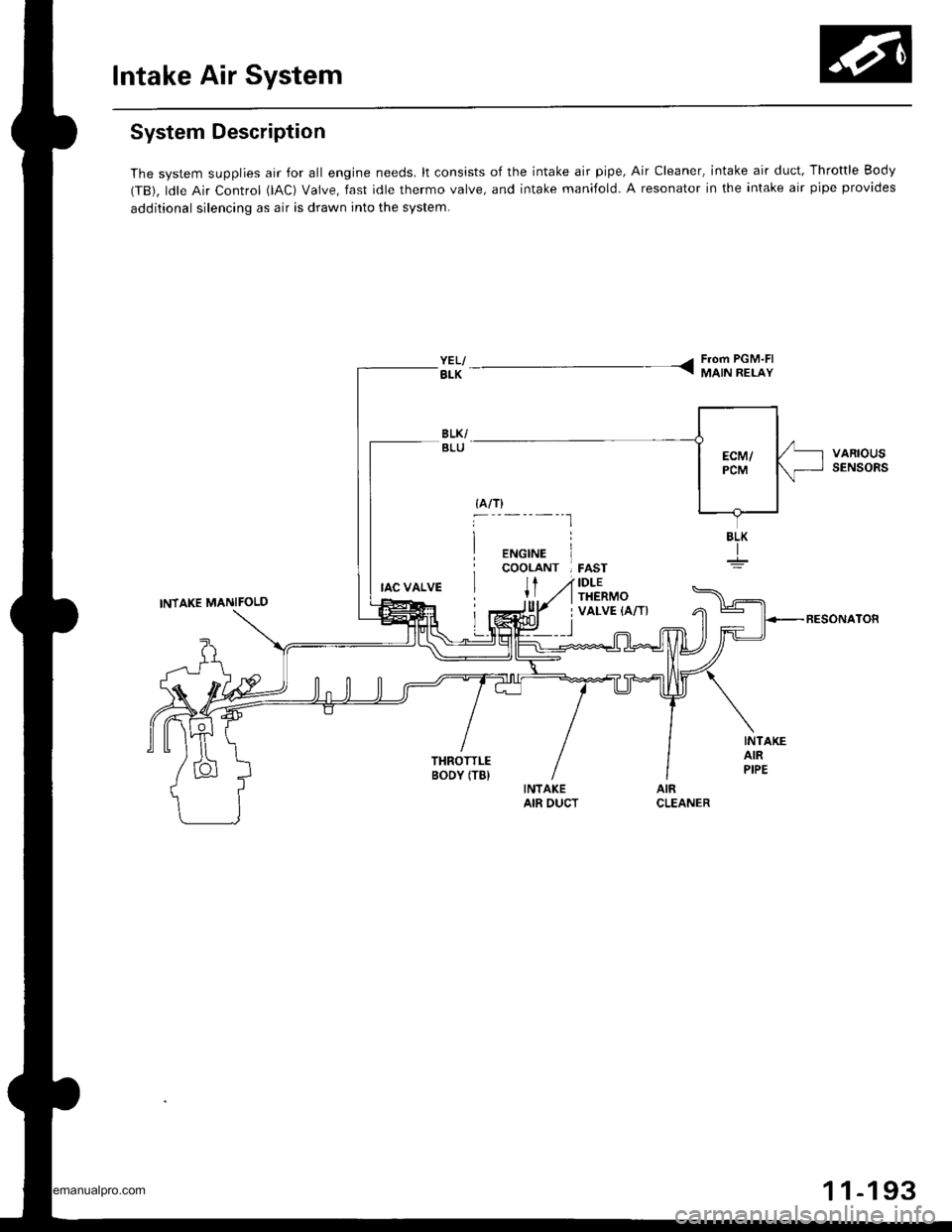
Intake Air System
System Description
The system supplies air for all engine needs. lt consists of the intake air pipe, Air Cleaner, intake air duct, Throttle Body
(TB), ldle Air Control (lAC) Valve, fast idle thermo valve, and intake manifold. A resonator in the intake air pipe provides
additional silencing as air is drawn into the system.
INTAKE MANIFOLD
YEL| - - Fiom PGM'FI
BLK T MAIN RELAY
IDLETHERMO
lJ- _iuo'u'j"'
INTAKEAIR DUCT
vaRtousSENSORS
FESONATON
THROTTLEBODY (TB)
1 1-193
www.emanualpro.com
Page 396 of 1395
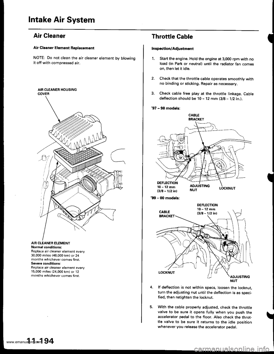
Intake Air System
Air Cleaner
Air Cleaner Eloment Rsplacomsnt
NOTE: Do not clean the air cleaner element by blowingit off with compressed air,
AIR CLEANER ELEMENTNo.mal conditions:Replace air cleaner element every30,000 miles {48,000 km) or 24months whichever comes first.Severe condition3:Replace air cleaner element every15,000 miles 124,000 km) or 12months whichever comes tirst.
m
11-194
Throttle Cable
Inrpection/Adiustmcnt
1. Stan the engine. Hold the engine at 3,000 rpm with noload (in Park or neutral) until the radiator fan comeson, then let it idle.
2. Check that the throttle cable operates smoothly withno binding or sticking. Repair as necessary,
3. Check cable free play at the throttle linkage. Cabtedeflection should be 10- 12 mm (3/8 - 1l2in.l.
'97 - 98 modols:
CABLEBRACKET
LOCKNUT
DEFLECTION10-12mmBIA- 112 i^l
'99 - 0O modsls:
lf deflection is not within specs, loosen the locknut,turn the adjusting nut untilthe deflection is as speci-fied, then retighten the locknut.
With the cable properly adjusted. check the throttlevalve to be sure it opens fully when you push theaccelerator pedal to the floor. Also check the throt-tle valve to be sure it returns to the idle position
whenever you release the accelerator pedal.
DEFLECTIONl0-12mft
Bla - 112 inl
NUT
www.emanualpro.com