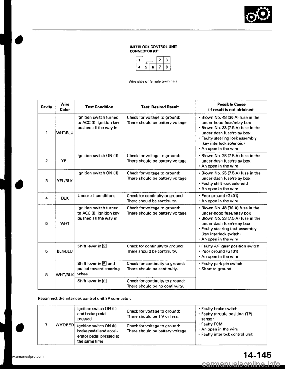
Throttle HONDA CR-V 2000 RD1-RD3 / 1.G Repair Manual
[x] Cancel search | Manufacturer: HONDA, Model Year: 2000, Model line: CR-V, Model: HONDA CR-V 2000 RD1-RD3 / 1.GPages: 1395, PDF Size: 35.62 MB
Page 661 of 1395

1?
4678
CavityWire
ColorTest CondhionTost: Desired RosultPossible Cause(lf result is not obtainedl
1WHT/BLU
lgnition switch turned
to ACC (l), ignition key
pushed all the way in
Check for voltage to ground:
There should be battery voltage.
Blown No. 48 {30 A} fuse in the
under-hood fuse/relay box
Blown No.33 (7.5 A) fuse in the
under-dash fuse/relay box
Faulty steering lock assembly
{key interlock solenoid)
An open in the wire
YEL
lgnition switch ON (ll)Check for voltage to ground:
There should be battery voltage.
Blown No.25 (7.5 A) fuse in the
under-dash fuse/relay box
An open in the wire
YEUBLK
lgnition switch ON (ll)Check for voltage to ground:
There should be baftery voltage.
Blown No. 25 (7.5 A) fuse in the
under-dash fuse/relay box
Faulty shift lock solenoid
An open in the wire
4BLKUnder all conditionsCheck for continuity to ground:
There should be continuity.
. Poor ground (G401)
. An open in the wire
5WHT
lgnition switch turned
to ACC (l), ignition key
pushed all the way in
Check for voltage to ground:
There should be battery voltage.
Blown No.48 (30 A) fuse in the
under-hood fuse/relay box
Blown No. 33 (7.5 A) fuse in the
under-dash fuse/relay box
Faulty steering lock assembly(key interlock switch)
An open in the wire
BLI(BLU
Shift lever in ECheck for continuity to ground:
There should be continuity,
Faulty Ay'T gear position switch
Poor ground (G101)
An open in the wire
8WHT/BLK
Shift lever in @ and
pulled toward steering
wneel
Check for continuity to ground:
There should be continuity.
Faulty park pin switch
Shon to ground
Shift lever in ECheck for continuity to ground:
There should be no continuity.
Wire side of female terminals
Reconnect the interlock control unit 8P connector.
14-145
7WHT/RED
lgnition switch ON (ll)
and brake pedal
presseo
Check for voltage to ground:
There should be 1 V or less.
Faulty brake switch
Faulty throttle position (TP)
sensor
Faulty PCM
An open in the wire
Faulty interlock control unit
lgnition switch ON (lll,
brake pedal and accel-
erator pedal pressed at
the same time
Check for voltage to ground:
There should be baftery voltage,
www.emanualpro.com
Page 673 of 1395

Road Test
NOTE: Warm up the engine to normal operating temperature (the radiator tan comes on).
1. Before testing, check the transmission fluid level, see page 14-160.
2. Apply the parking brake and block the wheels. start the engine, then shift to E {'97 - 98) or E {'gg - 00) position
while pressing the brake pedal. Press the accelerator pedal and release it suddenly. The engine should not stall.
3. Repeat same test in E position ('97 - 98 models).
4. Test-drive the vehicle on a flat road in the E or E position. Check that the shift points occur at approximate speeds
shown on a flat road. Also check for abnormal noise and clutch slippage.
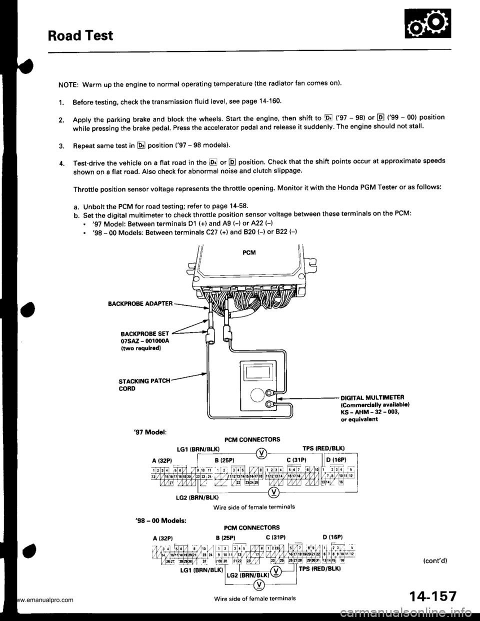
Throttle position sensor voltage represents the throttle opening. Monitor it with the Honda PGM Tester or as follows:
a. Unbolt the PCM for road testing; reJer to page 14-58.
b. Set the digital multimeter to check throttle position sensor voltage between these terminals on the PCM:
. '97 Model: Between terminals D'! (+) and A9 (-) or A22 {-}
. '98 - OO Models; Between terminals C27 (+) and 820 (-) or 822 {-)
BACKPROBE ADAPTER
BACKPROBE SETorsAz - 001moA(two roquircdl
STACKING PATCH
CORD
DIGiTAL MULTIMETER
{Comm€rcirllY .vailablc}KS-AHM-32-003,or equival.nt
'97 Model:PCM CONNECTORS
'98 - 0O Models:
A l32Pt
Wire side of female terminals
PCM CONNECTORS
B {25Pt c l31P}
(cont'd)
LGl (BRN/BLK)
'. //B 1 l'o ti , jl. to a 2r / / 11111t1.t nait la t1 t213tr / t6t, tl / / / / 1 3 / 10n v
t-'a:IM-&E -Llfiffi-fl)\"".'E
Wire side ot female termanals14-157
www.emanualpro.com
Page 674 of 1395

Road Test
(cont'd)
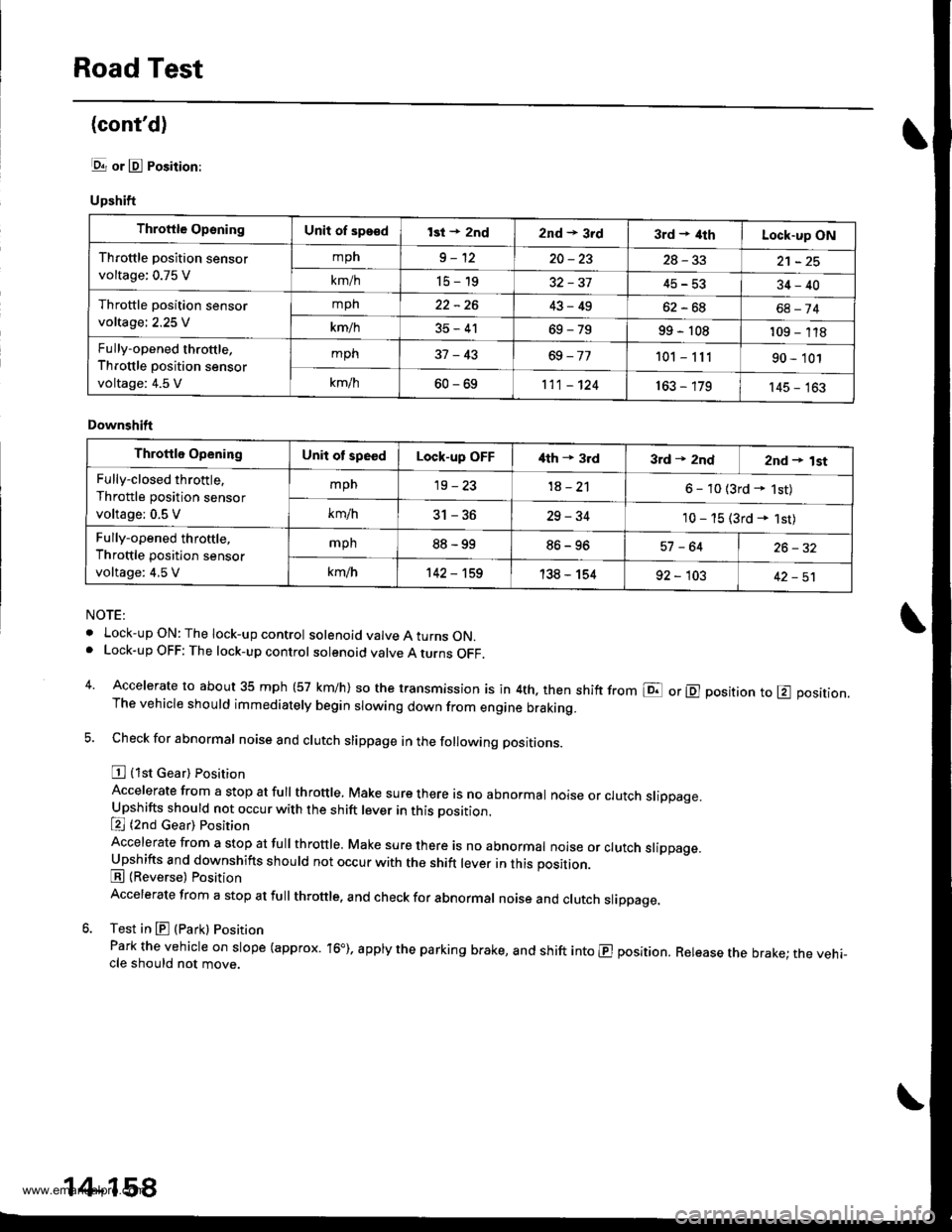
lgrr or E Position:
Upshift
NOTE:
. Lock-upON:The lock-up control solenoid valve A turns ON.. Lock-up OFF: The lock-up control solenoid valve A turns OFF.
4. Accelerate to about 35 mph (57 km/h) so the transmission is in 4th. then shift from E or E position to E position.The vehicle should immediately begin slowing down from engine braking.
5. Check for abnormal noise and clutch slippage in the following positions.
E {1st Gear) Position
Accelerate from a stop at full throttle, Make sure there is no abnormal noise or clutch slippage.Upshifts should not occur with the shift lever in this position.
E (2nd cear) Position
Accelerate from a stop at fuI throttre. Make sure there is no abnormar noise or crutch srippage.Upshifts and downshifts should not occur with the shift lever in this position.
E (Reverse) Position
Accelerate from a stop at full throttle. and check for abnormal noise and clutch slippage.
6. Test in E (Park) Position
Park the vehicle on slope (approx. 16"), apply the parking brake, and shift into E position. Release the brake; the vehi-cle should not move.
Throftle OpsningUnit of sps€dlsi + 2nd2nd * 3rd3rd + ilthLock-up ON
Throttle position sensor
voltage: 0.75 V
mph9-1220-2328-33
km/h15-1945-5334-40
Throttle position sensor
voltage; 2.25 V
mph22-2643-49oz - ott68-74
km/h35-4169-7999 - 108109 - 118
Fully-opened throttle,
Throttle position sensor
voltage: 4.5 V
mph37-43101 - 11190 - 101
k-/h60-69111 - 124163 - 179145 - 163
Downshift
Throttle OpeningUnit ot speedLock-up OFFi{th + 3rd3rd * 2ndznd + lst
Fully-closed throttle,
Throttle position sensor
voltage; 0.5 V
mpn19-231A - 2'l6 - 10 {3rd - 1st)
km/h5t-5D29-3410 - 15 (3rd * 1st)
Fully-opened throttle,
Throttle position sensor
voltage: 4,5 V
mph88-9986-9657 -6426-32
km/h142 - 't59138 - 15492 - 10342-51
14-158
www.emanualpro.com
Page 1174 of 1395
![HONDA CR-V 2000 RD1-RD3 / 1.G Repair Manual
Connector ldentification and Wire Harness Routing
Engino Wire Harness
Connecto; or
Terminal
Number of
CavitiesLocationConneqts toNotos
c101
c102
c103
c 104
c105
c105
c106
c 107
c 108
c 109
c]10
c1ll HONDA CR-V 2000 RD1-RD3 / 1.G Repair Manual
Connector ldentification and Wire Harness Routing
Engino Wire Harness
Connecto; or
Terminal
Number of
CavitiesLocationConneqts toNotos
c101
c102
c103
c 104
c105
c105
c106
c 107
c 108
c 109
c]10
c1ll](/img/13/5778/w960_5778-1173.png)
Connector ldentification and Wire Harness Routing
Engino Wire Harness
Connecto; or
Terminal
Number of
CavitiesLocationConneqts toNotos
c101
c102
c103
c 104
c105
c105
c106
c 107
c 108
c 109
c]10
c1l'l
c112
c113
c't 14
cl16
cl16
c117
c118
c119
c120
c121
c't22
c't23
c't25
cl26
cl27
cr 28
cl29
c130
c131
c132
c 133
c134
c134
c135
c 136
10
6
1
2
1
2
1
10
20
31
16
22
l0
l0'14
14
1
Left side of engine compartment
Left side of engine compartment
Middle of engine
Middle of engine
Left side of engine compartment
Left side of engine compartment
Middle of engine
Middle of engine
Middle of engine
Middle of engine
Middle of engine
Middle of engine
Middle of engine
Middle of engine
Middle of engine
Middle of engine
Middle of engine
Middle of engine
Middle of engine
Middle of engine
Middle of engine
Right side of engine
Middle of engine
Behind right kick panel
Under right side of dash
Under right side of dash
Under right side of dash
Under right side of dash
Under right side of dash
Right side of engine
Right side of engine
Middle of engine
Middle of engine
Middle of engine
Middle of engine
Middle of engine
Middle of engine
Left side of engine compartment
Middle of engine
Middle of engine
Main wire harness (C304)
Main wire harness (C305):'97 - 98 models
No. 1 fuel injector
Crankshaft speed fluctuation (CKF) sensor
Alternator
Alternator
Engine oil pressure switch
No.2 fuel injector
Evaporative emission (EVAP) purge
control solenoid valve
No. 3 fuel injector
No. 4 fuel injector
Primary heated oxygen sensor(Primary HO2S) (sensor 1)
Radiator fan switch
Coolant temperature sending unit
Engine coolant temperature (ECT) sensor
Mainshaft speed sensor
Lock-up control solenoid valve
Back-up light switch
Shift control solenoid valve
Linear solenoid valve
Countershaft speed sesnsor
Starter solenoid
Distributor
Junction connector
PCM
ECIWPCM
ECM/PCM
ECM/PCM
Main wire harness (C,|:}1)
IVT gear position switch
Vehicle speed sensor (VSS)
Throttle position (TP) sensor
MAP sensor
ldle air control (lAC)valve
lntake air temperature (lAT) sensor
Junction connector
Junction connector
Power steering pressure (PSP) switch
Junction connector
Knock sensor (KS)
A/r
USA
Canada
Alr
AlT
M/'r
Afi
'97mooel
'97 model'98 - 00
mooets
'99 - 00
models
T101
r102
Left side of en0ine companment
Right side of engine compartment
Alternator
Under-hood fuse/relay box
G101Middle of engineEngine ground, via engine wire harness
23-14
www.emanualpro.com