Connectors HONDA CR-V 2000 RD1-RD3 / 1.G Repair Manual
[x] Cancel search | Manufacturer: HONDA, Model Year: 2000, Model line: CR-V, Model: HONDA CR-V 2000 RD1-RD3 / 1.GPages: 1395, PDF Size: 35.62 MB
Page 583 of 1395
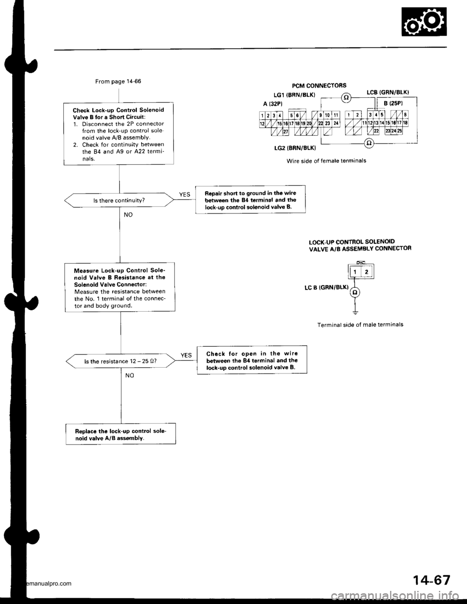
Check Lock-up Control SolenoidValve B lor a Short Circuit:1. Disconnect the 2P connectorfrom the lock-up control solenoid valve A/8 assembly.2. Check for continuity betweenthe 84 and A9 or A22 lermi_nals-
Repair short to ground in the wirebetween the 84 lerminal and the
lock-up conlrol solenoid valve B.
Me6aure Lock-up Control Sole_noid Valve B Resistance at the
Solenoid Valve Connector:Measure the resistance betweenthe No. 1 terminal of the connec-
tor and body ground.
Check lor open in the wire
bctween the 84 terminal and thelock-up control solenoid volva B.ls the resistance 12 - 25 0?
Replace the lock-up conttol sole-noid valve A/B ass6mbly.
From page 14 66PCM CONNECTORS
Wire side of female terminals
LOCK-UP CONTROL SOLENOID
VAI-VE A/B ASSEMBLY CONNECTOR
LC B (GRN/BLK)
14-67
www.emanualpro.com
Page 584 of 1395
Electrical Troubleshooting {'97 Model}
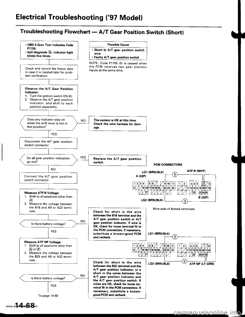
Troubfeshooting Flowchart- AIT Gear Position Switch (Short)
Po$ible Cause
' Short in A/T gear position switch
. Faulty A/T gear position switch
NOTE: Code P1705 (5) is caused whenthe PCM receives two gear positionanputs at the same time.
. OBO ll Scan Tool indicat€s CodeP1705.' Selt-diagnosis p1- indicator tightblinb Iive times.
Check and record the freeze datain case it is needed later for prob-lem verification.
Observe the A/T G€ar Po3itionIndicator:1. Turn the ignition switch ON lll).2. Observe the A./T gear positionindicator, and shilt to eachposition separately.
Does any indicator stay onwhen the shift lever is not inthat position?
The system is OK .t this time.Ch6ck ihe wii6 harness for dam-490,
Do allgear position indicatorsgo out?
Measure ATP R Voltago:1. Shitt to all positions other thantr.2. lMeasure the voltage betweenthe 816 and Ag or A22 termi-nals.Check tor 3hort in the wirebetwaen the 816torminal and thoA/T gear pGilion switch or A/Tgsar posiiion indicator. ff wire isOK, check for 10036 torminal flt inlhe PICM connectoB. It necessary,substitute a known-9ood PCMand recheck.
Measure ATP NP Voltage:1. Shift to all positions other thanNorE.2. Measure the vohage betweenlhe 825 and Ag or A22 termi-nals.Chock for ahort in the wirebetw€en tho 825 torminal end theA/T 96.r pGition indicstor, or asho.t in tha wiro! b€tween theA/T gear po3ition indicator andthe A/T g€ar position lwitch. lfwircs ar€ OK, ch6ck for loos€ ter-minal fit in the PCM connectors. Itnece3sary, substitute a known-good PCM and recheck.
ls there battery vohage?
PCM CONNECTORS
Wire side of female terminals
ATP NP {LT GRNI
14-68
To page 14-69
www.emanualpro.com
Page 585 of 1395
From page 14-68
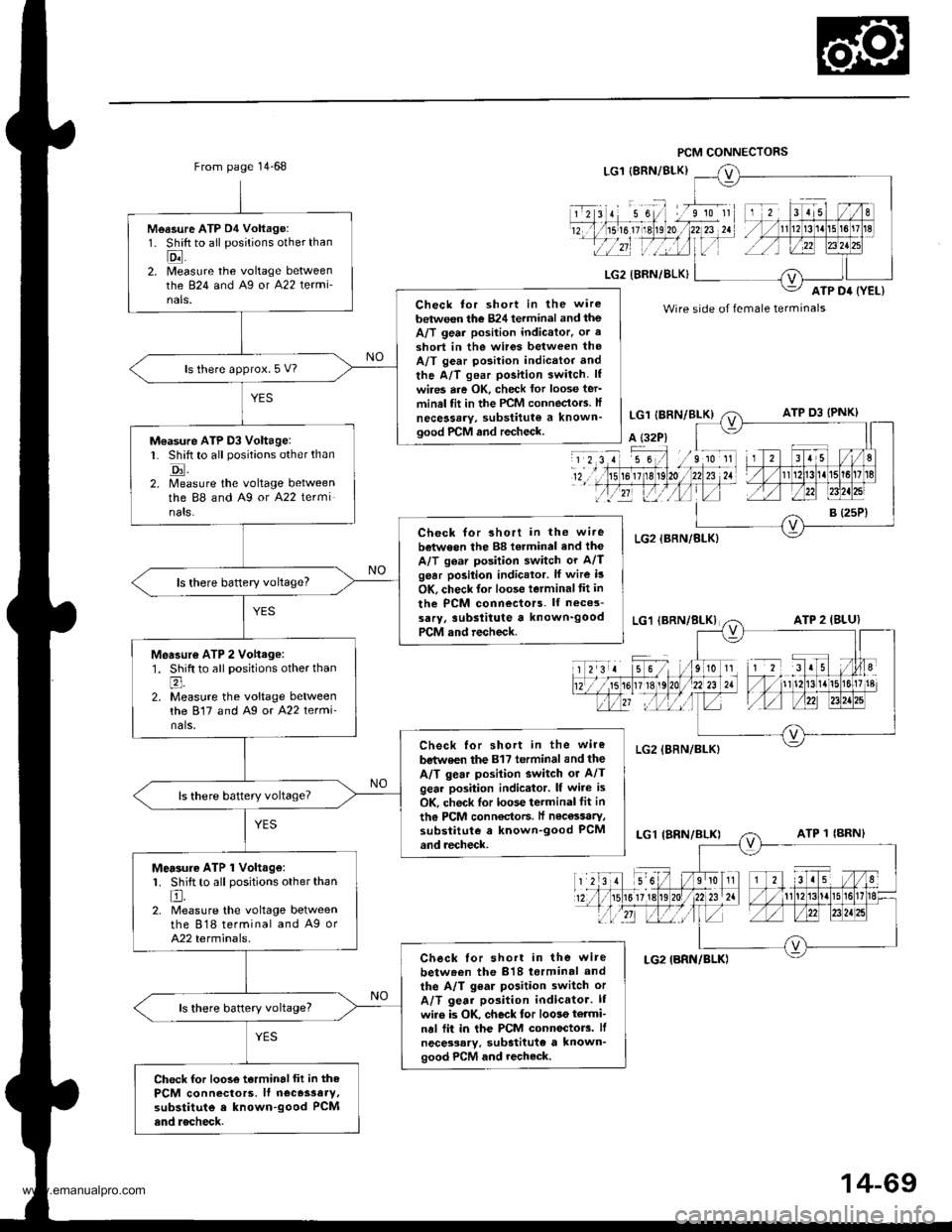
Measure ATP D4 Voltage:1. Shift to all positions other than
Eil2. [/leasure the voltage betweenthe 824 and Ag or A22 termi-nals.Check tor short in the wire
between the 824 terminal and theA/T geai position indicator. or a
3hort in the wir6s between theA/T gear position indicttor and
the A/T gear position switch. lf
wires are OK, check lor loose ter'minal fit in the PCM conneclo.s. lf
necessary, substitute a known'good PrCM and recheck.
ls there approx. 5 V?
M€asure ATP D3 Voltage:L Shift to all positions other than
tr.2. Measure the voltage betweenthe 88 and A9 or A22 terminats.
Check for short in the wi.ebetween the 88 torminal and the
A/T gear position switch or A/Tgear position indicator. lf wire i3
OK, check lor loose terminaltit in
the PCM connectors. lf neces-
sarY, 3ubslitute a known'goodPCM and recheck.
ls there baftery voltage?
Measur€ ATP 2 Vohage:1. Shift to all positions other thanl;
2. Measure the voltage betweenthe 817 and Ag or A22 termi'nals.
Check for short in the wire
bstwe€n the 817 terminal and the
A/T gear posilion switch or A/Tgear position indicator. lf wire is
OK, check lor loose terminal fit in
th6 PCM conn€ctoF. lf nec€ssaty,substitute a known-good PCMand recheck.
Mersure ATP 1 Volt.ge:1. Shift to all positions other than
El.2. Measure the voltage betweenthe 818 terminal and A9 orA22 terminals.
Check lor short in the wire
betw.en the 818 torminal and
the A/T gear position switch or
A/T gear position indicator. lI
wiro is OK. check for loose termi-nal fii in the PCM connectorc. lf
necessary. substitute a known'good PCM and recheck.
ls there battery voltage?
Check for loose terminalfit in thePCM connectors, lf neces3aty,substitute e known-good PCMend rocheck.
Wire side of female terminals
14-69
www.emanualpro.com
Page 587 of 1395
From page 14-70
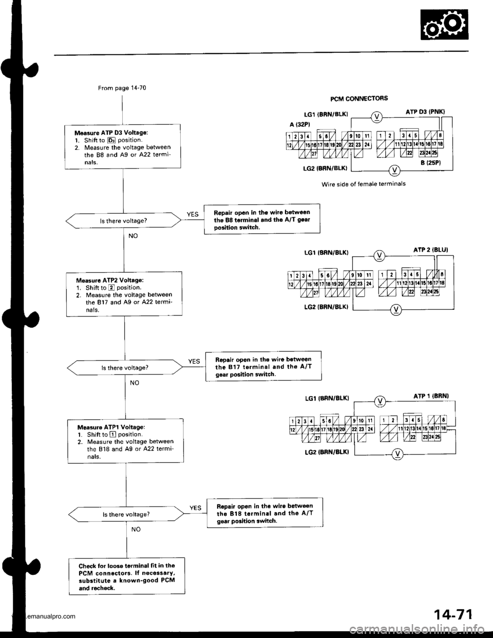
Measure ATP D3 Vohag€:1. Shift to E position.
2. Nleasure the voltage betweenthe 88 and Ag or A22 terminals,
Repair open in the wirg bstween
the 88 tolminal and tho A/l gear
oo3ition 3witch.
Msasure ATP2 Volttg6:'1. Shiftto E position.
2. Measure the voltage between
the 817 and A9 or A22 termi'nals.
Repair open in lhe wire between
the 817 terminal and tho A/Tgear position switch.
Moasure ATP1 Voltage:1. Shift to A position.
2. Measure the voltage betweenthe 818 and Ag or A22 termi-nats,
R€pair opon in the wiro betweenthe 818 terminll and the A/Tgoar poshion switch.
Check tor looso terminal fit in thePCM connectors. lf necossarY,substitute a known-good PCM
and rechock.
FCM CONNECTORS
Wire side of female terminals
www.emanualpro.com
Page 588 of 1395
Electrical Troubleshooting ('97 Model)
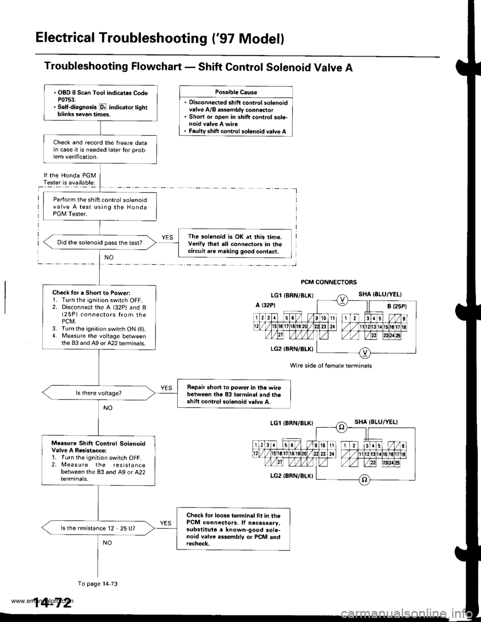
Troubleshooting Flowchart - Shift Control Solenoid Valve A
. Disconnected shift control solenoidvalve A/8 a$embly connector. Short or open in shift control sole-noid valve A wire
Possible Causo
shift control solenoid valve A
lf the Honda PGMTester is available:
I
PCM CONNECTORS
Wire side of female termin6ls
. OBD ll Scan Tool indicates CodeP0753.. Self-diagnosk E indicator lightblinks seven tim€s.
Check and record the freeze datain case it is needed later for problem verification.
Perform the shift control solenoidvalve A test using the HondaPGM Tester.
The sol€noid is OK at this time.Verify that all connectors in thecircuit are making good contact.
Did the solenoid pass the test?
Check tor a Short to Power:1. Turn the ignition switch OFF.2. Disconnect the A (32P) and B(2 5P) connectors from thePCM.3. Turn the ignition switch ON lll).4. Measure the voltage betweenthe 83 and Ag or A22 terminals.
Repair short to power in the wirebetween the 83 terminal and theshift control solenoid valve A.
Measure Shift Control SolenoidValve A Resistanco:1. Turn the ignition switch OFF.2, Measure the resistancebetween the 83 and A9 or A22termrnals,
Check tor loose terminal tit in thePCM connectors, lf necessaay,subslituie e known-good sole-noid valve assemblv or PCM andrech€ck.
ls the resistance 12 25 {)?
To page l4-73
14-72
www.emanualpro.com
Page 590 of 1395
Electrical Troubleshooting ('97 Model)
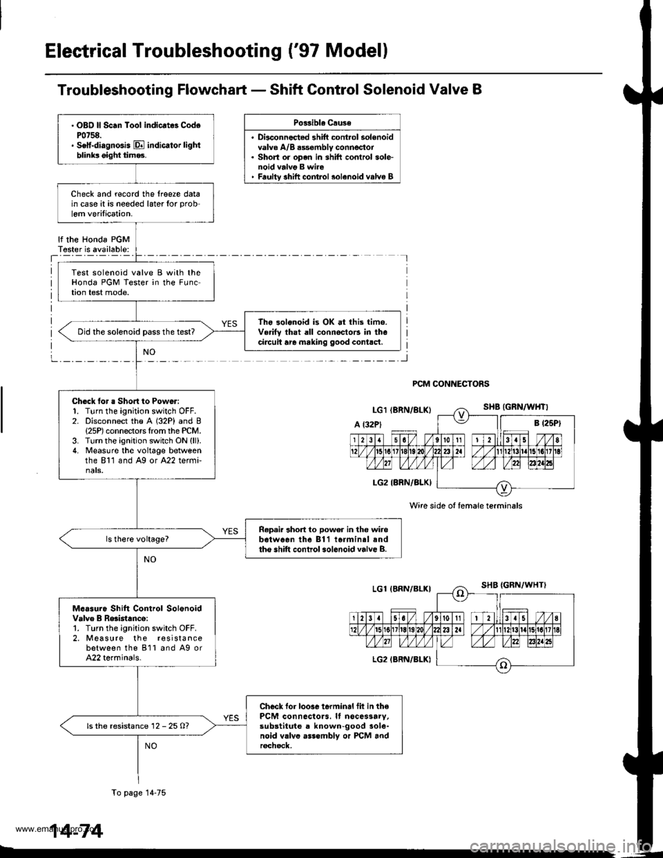
Troubleshooting Flowchart - Shift Control Solenoid Valve B
Po33ibla Crusa
. Disconnec{ed shift cont.ol solenoidvalve A/B dssombly connector. Short or open in shift conlrol sole-noid valvg B wire' Faultv shift comrol 3olenoid valvo B
lf the Honda PGMT€ster is available:
PCM CONNECTORS
Wire side ot female terminals
. OBO ll Scan Toot indicrt8 CodoP0758.. Setf-diagnGis E indicator lightblinks oight tim93.
Check and r€cord the lreere datain case it is needed later for prob
lem verilication.
Test solenoid valve B with theHonda PGM Tester in the FLrnction test mode.
The 3olonoid is OK at this time.Verifv that all connoctors in thecircuit are making good contlct.Did the solenoid Dass the test?
Chock tor a Sho.t to Power:1. Turn the ignition switch OFF.2. Disconnect the A (32P) and B{25P) connectors Irom the PCM.3. Turn the ignition switch ON (ll).
4. Measuro the voltage botveenthe 811 and Ag or A22 termi-nats.
R.p.ir 3hort to power in the wirebotwo€n the 811 iormin.l andtho shift control sol.noid valve B.
M.6sure Shift Control SolonoidValve B Reaistanco:1. Turn the ignition switch OFF.2. Measure the r€sistancebetween the 811 and A9 orA22 terminals.
Checl lor loosc terminal fil in thePCM connactors. It nocessarv,substitute a known-good aole-noid vllvo asssmbly or PCM andr6chsck,
ls the resistance 12 - 25 O?
To page 14-75
14-74
www.emanualpro.com
Page 591 of 1395
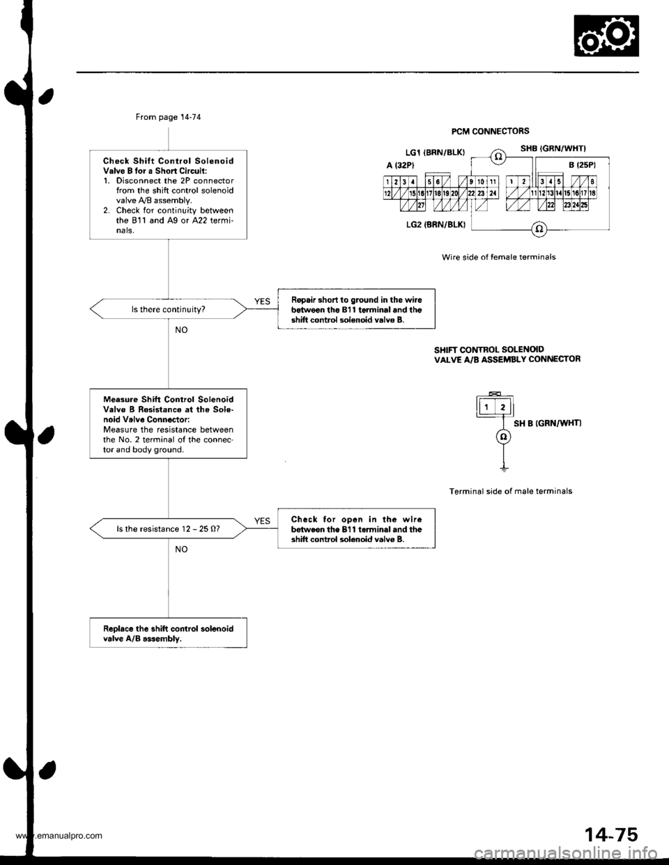
From page 14-74
Check Shift Control SolenoidValvo B tor a Short Circuil:1. Disconnect the 2P connectorfrom the shift control solenoidvalve y'y'8 assembly.2. Check for continuity betweenthe 811 and Ag or A22 termi-nals,
Ropair short to ground in the wireb64w€€n tho 811 torminal and lhgshift control solenoid valvo B.
Meesure Shift Control SolenoidValve B Rosistance at lh€ Sole-noid Vrlve Connector:Measure the resistance betweenthe No. 2 terminal ol the connector and body ground.
Check tor open in the wirebdtweon the 811 torminal and theshift control sol€noid valv6 B.ls the resistance 12 - 25 O?
Reolace the shift control solenoidvalve A/B asJembly,
PCM CONNECTORS
Wire side of female terminals
SHIFT CONTROL SOLENOIDVALVE A/B ASSEi'BLY CONNECTOR
ti;Tll
I sH B |GRN/W{T|
o
YII
Terminal side of male terminals
14-75
www.emanualpro.com
Page 597 of 1395
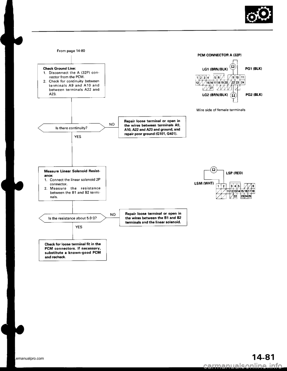
Ch€ck Ground Lin€:1. Disconnect the A (32P) con-nector from the PCM.2. Check lor continuity betweenterminals Ag and A10 andbetween terminals A22 andA.23.
Repair loose terminal or opon inth€ wires between terminals A9,A10, A22 and A23 and g.ound, andrepair poor ground lG101, G4011.
Measure Linear Solenoid R*ist-
ance:1. Connect the linear solenoid 2P
connector.2. Measure the resistancebetween the 81 and 82 terminals,
Ropair loos€ terminal or op6n in
the wiles between th€ 81 and 82
l6rminals and the linear solenoid.ls the resistance about 5.0 0?
Chock lor loose tarminalfit in thePCM connectors. lf necosaarv,subsiituto a known-good PCMand recheck.
PGl IBLKI
PG2 (ALKI
Wire side of temale terminals
14-81
www.emanualpro.com
Page 605 of 1395
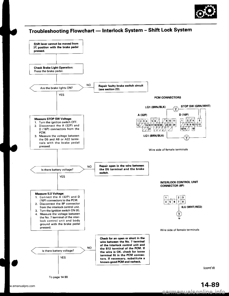
Troubleshooting Flowchart - Interlock System - Shift Lock System
PCM CONNECTORS
Wire side of lem6le termanals
INTERLOCK CONTROL UNIT
CONNECTOR I8P)
ILU IWHT/REDI
(cont'd)
Shift lever cannot be moved from
E] position with the brake P€delpreiseo.
Chock Brake Light Operation:Press the brake pedal.
Repsir fauhy brake switch circuit
{seo s€ction 231.Are the brake lights ON?
M€asure STOP SW voltage:l� Turn the ignition switch OFF.
2. Disconnect the A (32P) and
D (16P) connectors lrom thePCM.3. Measlre the voltage between
the D5 and Ag or A22 terma
nals with the brake Pedalpressed,
Repair opon in the wi.e be{w.enthe D5 terminal and the br.ke
switd!.
Measur€ ILU vohage:1. Connect the A {32P) and D
116P) connectors to the PCM.2. Disconnect the 8P connectorfrom the interlock control unit
3. Turn the ignition switch ON (ll).
4. Measure the voltage betweenthe No.7 terminalofthe inter
lock control unit and bodyground with the brake Pedalpressed,
Ch€ck for an opon or thon in the
wire Mwoon tho No. 7 terminrl
of the inte ock control unit and
the 812 termin.l of the PcM. ll
the wirs is OK, check tor loo3e
terminal fit in the PCM connec_
to13. ll nece3sary,3ubstitute a
known-good PCM and rechock.
ls there battery voltage?
To page 14 90
14-89
www.emanualpro.com
Page 608 of 1395
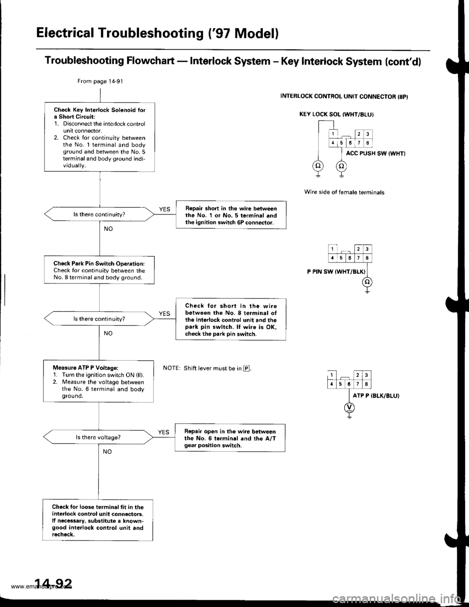
Electrical Troubleshooting {'97 Model)
Troubleshooting Flowchart - Interlock System - Key Interlock System lcont'dl
INTERLOCK CONTROL UNIT CONNECIOR {8PI
KEY LOCK SOL {WHT/8I-UI
ACC PUSH SW IWHTI
Wire side of female terminals
ATP P (BLK/BLU)
Check Key Interlock Solenoid fora Short Circuit:1. Disconnect the interlock controlunit connector.2. Check for continuity betweenthe No. l terminal and bodyground and between the No.5terminaland body ground indi-vidually.
Repair short in the wire betweenthe No. 1 or No. 5 terminal andthe ignition switch 6P connector.
ls there continuity?
Check Park Pin Switch ODeration:Check for continuity between theNo. I terminal and body ground.
Check tor shori in the wirebetwo€n the No. 8 terminal otthe interlock control unit and thepark pin switch. lf wire is OK,ch6ck the park pin switch.
ls there continuity?
Measu16 ATP P Voltage:1. Turn the ignition switch ON lll).2. Measure the vohage betweenthe No.6 terminal and bodyground.
R6pei. open in the wire betweenthe No. 6 i€rminal and the A/Tgea. position switch.
Check for loose terminalfit in theinterlock control unil connectors.lf necessery, substitute a known-good interlock control unit andr6check.
From page 14-91
Shift lever must be in E.
14-92
www.emanualpro.com