Section 23 HONDA CR-V 2000 RD1-RD3 / 1.G Repair Manual
[x] Cancel search | Manufacturer: HONDA, Model Year: 2000, Model line: CR-V, Model: HONDA CR-V 2000 RD1-RD3 / 1.GPages: 1395, PDF Size: 35.62 MB
Page 359 of 1395
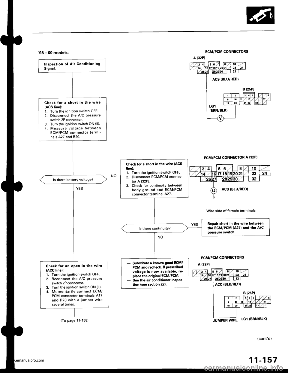
'98 - 00 models:ECM/PCM CONNECTORS
ECM/PCM CONNECTOR A (32PI
Wire side of female terminals
ECM/PCM CONNECTORS
A (32P1
ACC (BLK/REOI
LG1 (BRN/BLKI
{cont'd)
11-157
A {32P1
Check for a shott in the wire
{ACS linel:1. Turn the ignition switch OFF.
2. Disconnect the A/C Pressureswitch 2P connector.3. Turn the ignition switch ON (ll)
4. Measure vo ltage betweenECM/PCM connector terml
nals A27 and 820.
Check tor . short in the wire IACSlinel:1. Turn the ignition switch OFF.
2. Disconnect ECM/PCM connec-tor A (32P).
3. Check for continuity betweenbody ground and ECM/PCMconnector terminal A27.
ls there battery voltage?
R.oak short in the wile between
rhe ECM/PCM (A271 and the A/C
Dressure switch.ls there continuitv?
Sub6titute a known{ood ECM/
rcM and recheck. lf pte6cribed
voltage i3 now available, re'pl.ce the origioal ECM/rcM.See ih6 air conditioner inspec-
tion (s6e section 221.
Check for an open in the wire(ACC line):'1. Turn the ignition switch OFF.
2. Reconnect the A/C Pressureswitch 2P conneclor.3. Turn the ignition switch ON (ll).
4. Momentarily connect ECM/PCM connector terminals A17
and 820 with a jumPer wireseveralllmes,
{To page 11 158)JUMPER WIRE
www.emanualpro.com
Page 360 of 1395
ldle Control System
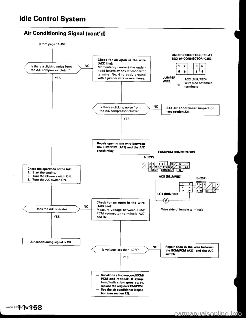
Air Gonditioning Signal (cont'd)
JUMPERWIRE
UNDER-HOOD FUSE/RELAYBOX 9P CONNECTOR {G'52I
23a
5589
ACC (BLK/R
Wire side otACC (BLK/RED'
Wire side otfemaleterminals
ECM/PCM CONNECTORS
Wire sid€ of female torminals
(From page '11,157)
Check Ior dn opon in the wiroIACC linel:Momentarily connect the under-hood fuse/relay box 9P connectorterminal No. 5 to body groundwith a jumper wire several times.
ls there a clicking noise lromthe y'y'C compressor clutch?
ls there a clicking noise fromtho A,/C comprossor clutch?Sae rir conditional in3pactionlroa saction 221.
Repai. open in th6 wiro lr€twlanthe ECM/PCM lAl7l .nd tho A/Cclutch rolay.
Check tho op.ration of tho A/C:1. Stan the engine.2. Turn the blower switch ON.3. Turn the Ay'C switch ON.
ChGGk for an open in the wi.eIACS linel:Measure voltage betweon ECM/PCM connector terminals A27and 820.
Does the !y'C operate?
Air conditioning 3ignal i3 OK.
Rap.ir opon in the wir6 bdtunaanrh. Ecil/FcM lA27l rnd rh. A/crwitch.
ls voltage less than 1.0 V?
Sub6lftna a known{ood ECM/PCM and rechock. lf symp-tom/indicetion goes away.roplace the original ECM/rcM.See the ah conditionor inspoc-tion {3e€ section 22},
www.emanualpro.com
Page 370 of 1395
ldle Control System
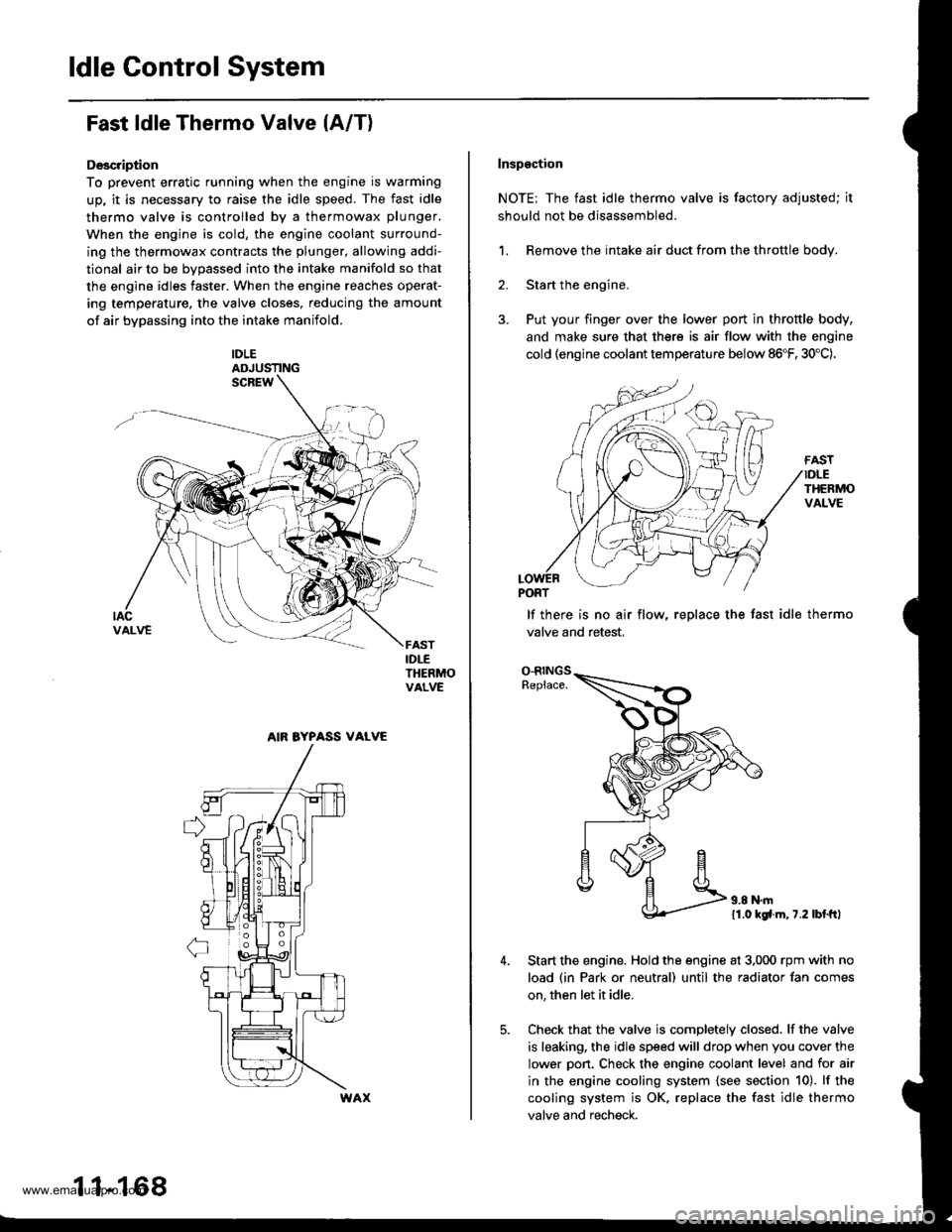
Fast ldle Thermo Valve lA/T)
Description
To prevent erratic running when the engine is warming
up, it is necessary to raise the idle speed. The fast idle
thermo valve is controlled by a thermowax plunger.
When the engine is cold, the engine coolant surround-
ing the thermowax contracts the plunger, allowing addi-
tional air to be bvDassed into the intake manifold so that
the engine idles faster. When the engine reaches operat-
ing temperature. the valve closes, reducing the amount
of air bypassing into the intake manifold.
IDLEADJUSTING
IDLETHERMOVALVE
AIR BYPASS VALVE
11-168
Inspgction
NOTE: The fast idle thermo valve is factory adjusted; it
should not be disassembled.
1. Remove the intake air duct from the throttle body.
2. Start the engine,
3. Put your finger over the lower port in throttle body,
and make sure that there is air flow with the engine
cold (engine coolant temperature below 86"F, 30'C).
lf there is no air flow, replace the fast idle thermo
valve and retest,
O-RINGSReplace.
11.0 kgfl.m, 7.2 lbl.ftl
Start the engine. Hold the engine at 3,000 rpm with no
load (in Park or neutral) until the radiator fan comes
on, then let it idle.
Check that the valve is completely closed. lf the valve
is leaking, the idle speed will drop when you cover the
lower pon. Check the engine coolant level and for air
in the engine cooling system {see section 10). lf the
cooling system is OK, replace the fast idle thermo
valve and recheck.
www.emanualpro.com
Page 372 of 1395

ldle Control System
ldle Speed Setting (cont'd)
38 - 0O mod6l3:
NOTE: Before setting the idle speed, check the follow-
ing items:- The MIL has not been reported on.- lgnition timing- Spark plugs
- Air cleaner- PCV system
1. Start the engine. Hold the engine at 3.000 rpm with
no load (in Park or neutral) until the radiator fan
comes on, then let it idle.
Connect a tachometer.
Disconnect the IAC valve 2P connector and the EVAP
purge control solenoid valve 2P connector.
CONTROLSOLENOID VALVE
SOLENOID VALVE
lf the engine stalls, restart the engine with the accel-
erato. pedal slightly depressed. Stabilize the rpm at
1,000, then slowly release the pedal until the engine
idles.
Che€k the idle in no-load conditions: headlights, blow-
er fan, rear defogger, radiator fan, and air conditioner
are not operating,
ldle speed should bo:
480 t 50 rpm {in PErk or noutrall
11-170
lf necessary, adjust the idle speed, by turning the
idle adjusting screw.
After adjusting the idle speed, recheck the ignition
timing (see section 4). lf it is out of spec, go back to
steo 4.tDt.E
6. Turn the ignition switch OFF.
7. Reconnect the 2P connectors to the IAC valve and
the EVAP purge control solenoid valve, then do the
ECM/PCM reset procedure.
8. Restart and idle the engine with no-load conditions
for one minute, then check the idle speed.
ldle speod should be:,98 model:
750 t 50 rpm tin Park or neutral)'9!l - 00 modsls:
730 i 50 lpm lin Psrk or neutral)
NOTE: lf the idle speed increases to 780 t 50 rpm(770 1 50 rpml*, this means the EVAP system is
purging the canister. To stop the purging temporari-
ly, raise the engine speed above 1,000 rpm with the
accelerator pedal, then slowly release the pedal.*: '99 - 00 models
9. Let the engine idle for one minute with the head-
lights (Low) ON, and check the idle speed.
ldle speed should be:
38 mod6l:
750 f 50 rpm (in Palk or neutrall'99 - 00 modols:
730 t 50 rpm (in Palk or neutral)
10. Turn the headlights off. Let the engine idle for one
minute with the heater fan switch at Hl and air con-
ditioner on, then check the idle speed.
ldls spqed should be:'98 model:
780 t 50 rpm (in Park or neutrall'99 - 00 mod€ls:
7701 50 rpm lin Park or neutral)
lf the idle speed is not within specification. see the
Symptom Chart on page 11-64.
ADJUSTING
www.emanualpro.com
Page 385 of 1395
Fuel Pump
Testing
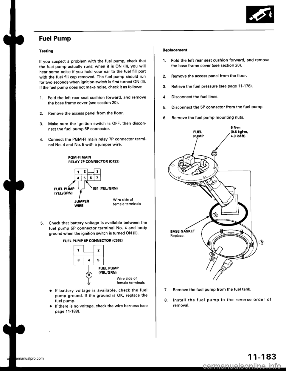
lf you suspect a problem with the fuel pump, check that
the fuel pump actually runs; when it is oN (ll), you will
hear some noise if you hold your ear to the fuel fill port
with the fuel fill cap removed. The fuel pump should run
for two seconds when ignition switch is first turned ON (ll).
lf the fuel pump does not make noise, check it as follows:
1. Fold the left rear seat cushion forward, and remove
the base frame cover (see section 20).
2, Remove the access panel from the floor.
3. Make sure the ignition switch is OFF, then discon-
nect the fuel pumP 5P connector.
4. Connect the PGM-FI main relay 7P connector termr-
nal No. 4 and No, 5 with a jumper wire.
PGM.FI MAINRELAY 7P CONNECTOR (Cit:}2l
I'TtlJilt f -r'-r ll.l5l517l,frTt-,at\FUEL pUMp Lr- . tcl tyEL/cRNl
rYEL/cRNl IIJUMPER Wir€ side of
WIRE female terminals
5. Check that battery voltage is available between the
fuel pump 5P connector terminal No. 4 and body
ground when the ignition switch is turned ON (ll).
FUEL PUMP 5P CONNECTOR {C562}
12
3a5
lf battery voltage is available, check the fuel
pump ground. lf the ground is OK, replace the
fuel oumo.
lf there is no voltage, check the wire harness (see
page 11-188).
FUEL PUMP(YEL/GRNI
wire side offemale terminals
Raplac6mont
1. Fold the left rear seat cushion forward, and remove
the base frame cover (see section 20).
2. Remove the access panel from the floor.
3, Relieve the fuel pressure (see page 11-178).
4. Disconnect the fuel lines.
5. Disconnect the 5P connector from the fuel pump.
6. Remove the fuel pump mounting nuts.
7. Remove the fuel pump from the fuel tank.
Install the fuel pump in the reverse order of
removal.
8.
11-183
www.emanualpro.com
Page 386 of 1395
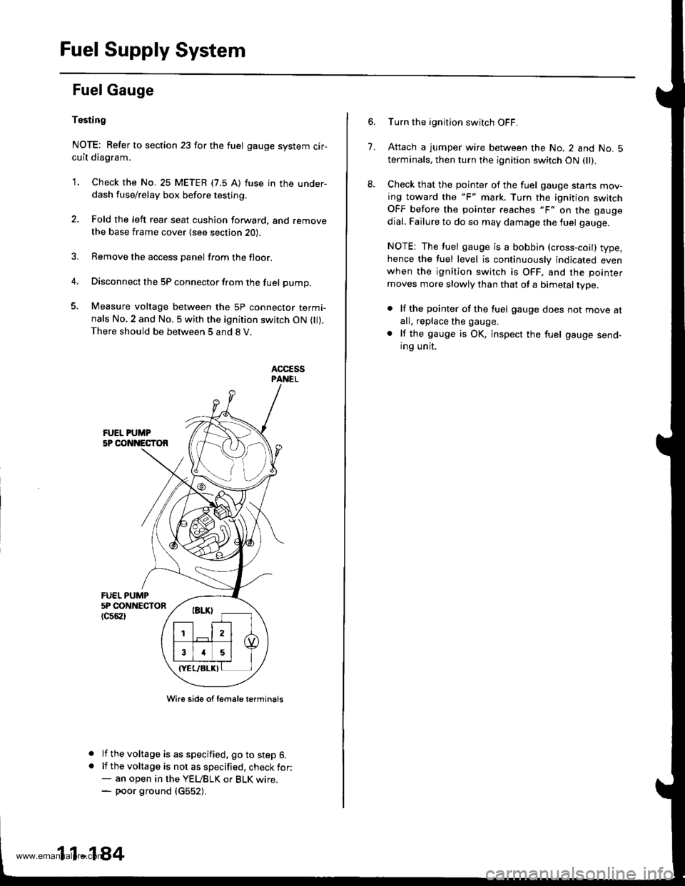
Fuel Supply System
Fuel Gauge
Tssting
NOTE: Refer to section 23 for the fuel gauge system cir-cuit diagram.
'1. Check the No. 25 METER (7.5 A) fuse in the under-dash fuse/relay box before testing.
2. Fold the left rear seat cushion forward, and remove
the base frame cover {see section 20).
3. Remove the access panel from the floor.
4. Disconnect the 5P connector from the fuel pump.
5. Measure voltage between the 5P connector termi-nals No.2 and No. 5 with the ignition switch ON ( ).There should be between 5 and 8 V.
FUEL PUMP5P CONNECTOR
tc56al
a
a
Wire side of female t€rminals
lf the voltage is as specified, go to step 6.lf the voltage is not as specified, check for:- an open in the YEUBLK or BLK wrre.- poor ground (c552).
11-184
7.
Turn the ignition switch OFF.
Attach a jumper wire between the No. 2 and No. 5terminals, then turn the ignition switch ON fll).
Check that the pointer of the fuel gauge starts mov-ing toward the "F" mark. Turn the ignition switchOFF before the pointer reaches "F" on the gauge
dial. Failure to do so may damage the luel gauge.
NOTE: The fuel gauge is a bobbin (cross-coil) type,hence the fuel level is continuously indicated evenwhen the ignition switch is OFF, and the pointer
moves more slowly than that of a bimetal type.
. lf the pointer of the fuel gauge does not move atall. replace the gauge.
. lf the gauge is OK, inspect the fuel gauge send-ing unit.
www.emanualpro.com
Page 387 of 1395
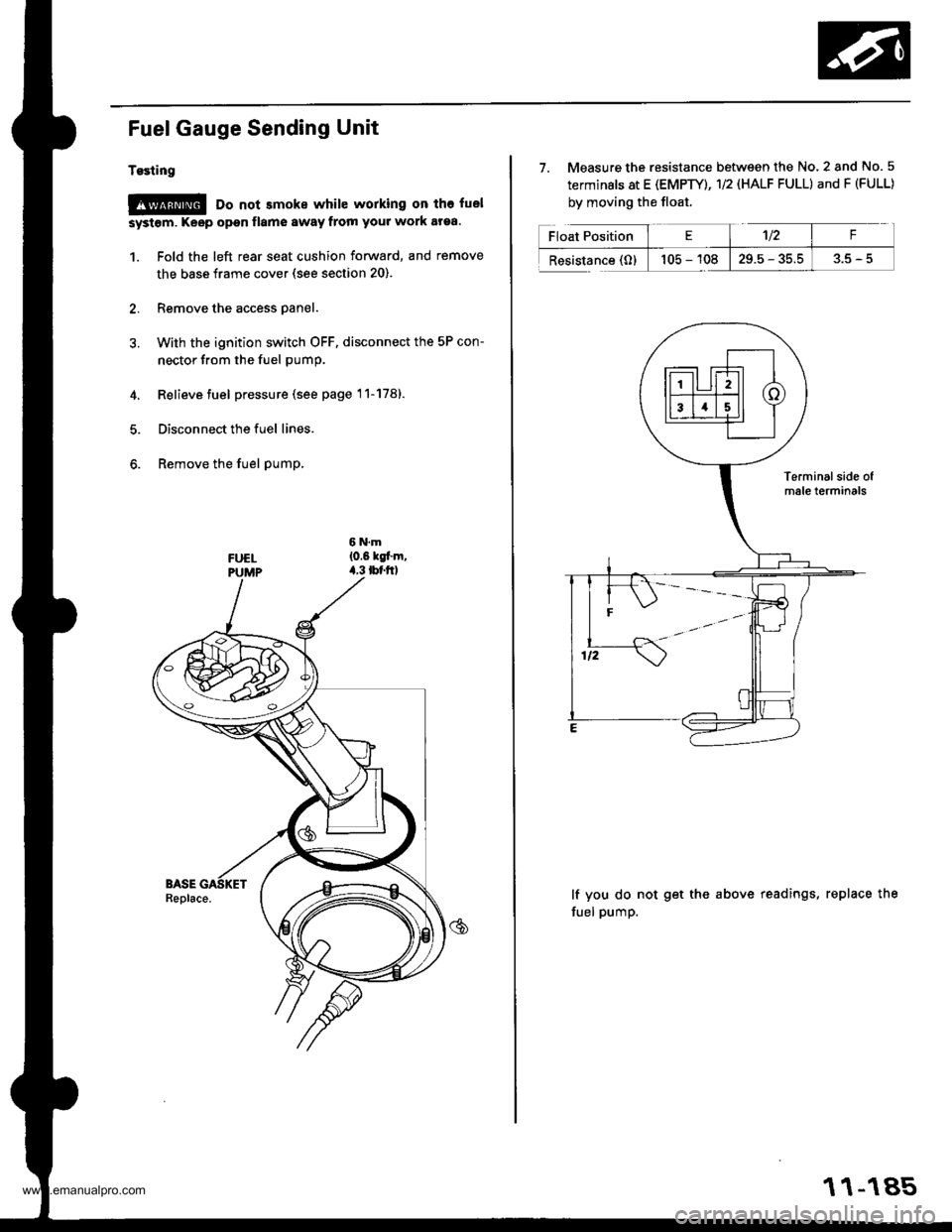
Fuel Gauge Sending Unit
Tgsting
@ Do not smoke while working on tho fuel
systom. Keop open flamo 8waY from your work araa.
1. Fold the left rear seat cushion forward, and remove
the base frame cover (see section 20).
2. Remove the access panel.
3. With the ignition switch OFF. disconnect the 5P con-
nector from the fuel pump.
4. Relieve fuel pressure (see page 11-178).
5. Disconnect the fuel lines.
6. Remove the fuel pump,
7. Measure the resistance between the No. 2 and No. 5
terminals at E (EMPTY), 1/2 (HALF FULL) and F (FULL)
by moving the float.
lf you do not get the above readings, replace the
fuel pump.
11-185
www.emanualpro.com
Page 388 of 1395
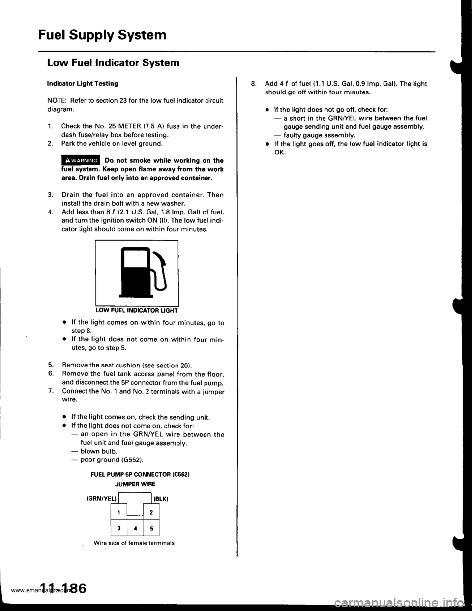
Fuel Supply System
Low Fuel Indicator System
Indicator Light Testing
NOTE: Refer to section 23forthe lowfuel lndicator circuit
clragram.
1. Check the No. 25 METER (7.5 A) fuse in the under-
dash fuse/relay box before testing.
2. Park the vehicle on level ground.
@ Do not smoke while working on the
fuel system. Keep open flame away trom the work
aroa. Drain fuel only into an approved container.
Drain the fuel into an aoDroved container. Then
install the drain bolt with a new washer.
Add less than 8 f (2.1 U.S. Gal. 1.8 lmp. Gal) of fuel,
and turn the ignition switch ON {ll). The low fuel indi-
cator light should come on within four minutes.
INDICATON LIGHT
. lf the light comes on within four minutes, go tostep 8.
. lf the light does not come on within four min-
utes. go to step 5.
Remove the seat cushion (see section 20).
Remove the fuel tank access panel from the floor,
and disconnect the 5P connector from the fuel pump,
Connect the No. 1 and No. 2 terminals with a jumper
wire.
. lf the lightcomeson, checkthe sending unit.. lf the light does not come on, check for:- an open in the GRN/yEL wire between thefuel unit and fuel gauge assembly.- blown bulb.- poor ground (G552).
FUEI- PUMP 5P CONNECTOR (C562)
JUMPER WIRE
IGRN/YEL}
7.
1 1-1 86
Wire sid€ ol tem€le terminals
8. Add 4 / of fuel (1.1 U.S. Gal, 0.9 lmp. Gal). The light
should go off within four minutes.
. lJ the light does not go off, check for:- a short in the GRNA/EL wire between the fuel
gauge sending unit and fuel gauge assembly.- faulty gauge assembly.
. lf the light goes off, the low fuel indicator light is
oK.
www.emanualpro.com
Page 389 of 1395
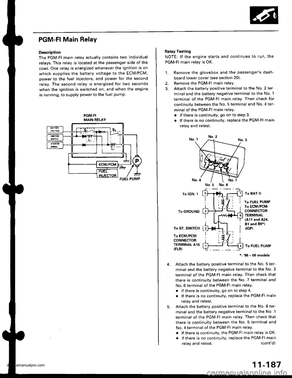
PGM-FI Main Relay
Description
The PGM-Fl main relav actuallv contains two individual
relays. This relay is located at the passenger side of the
cowl. One relay is energized whenever the ignition is on
which supplies the battery voltage to the ECM/PCM,
power to the fuel injectors, and power for the second
relay. The second relay is energized for two seconds
when the ignition is switched on, and when the engine
is running, to supply power to the fuel pump
PGM.FIMAIN RELAY
Belay Testing
NOTE: lf the engine starts and continues to run, the
PGM-FI main relay is OK.
1. Remove the glovebox and the passenger's dash-
board lower cover (see section 20).
2. Remove the PGM-FI main relay
3. Aftach the battery positive terminal to the No. 2 ter-
minal and the battery negative terminal to the No. 1
terminal of the PGM-Fl main relay. Then check for
continuity between the No. 5 terminal and No. 4 ter-
minal of the PGM-FI main relay
. lfthere is continuity, go on to step 3.
. lf there is nocontinuity, replacethe PGM-Fl main
relav and retest.
No.2
To lGN. 1
To GROUND
To ST. SWITCH
To ECM/PCMCONNECTORTERMINAL A16(FLR)
To BAT O
To FUEL PUMPTo ECM/PCMCONNECTORTERMINAL(411 and A24,Bl .nd Bgal(IGP)
To FUEL PUMP
98 - 00 models
Attach the batterv Dositive terminal to the No. 5 ter-
minal and the battery negative terminal to the No. 3
termjnal of the PGM-Fl main relay. Then check that
there is continuity between the No. 7 terminal and
No. 6 terminal of the PGM-FI main relay.
. lf there is continuity, go on to step 4.
. lf there is nocontinuity, replacethe PGM-Fl main
relay and retest.
Attach the batterv oositive terminal to the No.6 ter-
minal and the battery negative terminal to the No. 1
terminal of the PGM-Fl main relay. Then check that
there is continuitv between the No. 5 terminal and
No. 4 terminal of the PGM-Fl main relay.
. lf there is continuity, the PGM-Fl main relay is OK.
. lf there is nocontinuity, replacethe PGM-FI main
5.
(cont'd)
11-147
No.5 No.5
relay and retest.
www.emanualpro.com
Page 393 of 1395
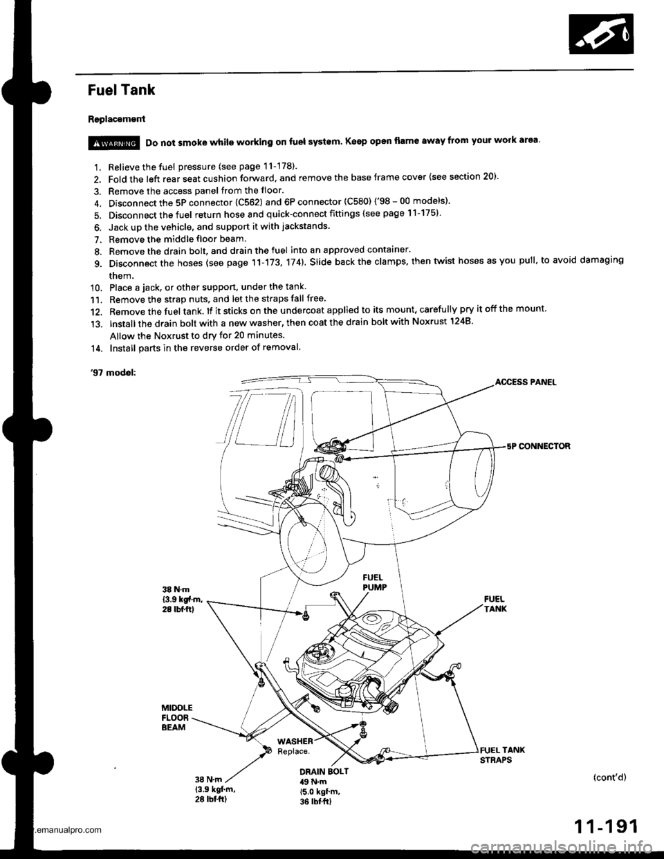
Fuel Tank
Replacement
1. Relieve the fuel pressure (see page 11-178).
2. Fold the left rear seat cushion forward, and remove the base frame cover {see section 20).
3. Remove the access panel from the floor.
4. Disconnect the 5P connector 1C562) and 6P connector (C580) ('98-00 models)'
5. Disconnect the fuel return hose and quick-connect fittings {see page 11-175}
6. Jack up the vehicle, and support it with jackstands.
7. Remove the middle floor beam.
8. Remove the drain bolt, and drain the fuel into an approved contaaner.
g. Disconnect the hoses (see page 11-173, 174). slide back the clamps. then twist hoses as you pull, to avoid damaging
them.
10. Place a jack, or other suppon, under the tank
11. Remove the strap nuts, and let the straps fall free
12. Remove the fuel tank. lf it sticks on the u ndercoat applied to its mount, carefu lly pry it off the mount,
'13. lnstallthe drain bolt with a new washer, then coat the drain bolt with Noxrust 1248'
Allow the Noxrust to dry for 20 minutes.
14. Install parts in the reverse order of removal.
'97 modol:AOCESS PANEL
CONNECTOR
@ Do not smoke while working on fuol systam Keep open flame away from your work area'
DRAIN EOLT49 N.m15.0 kgf'm,36 rbt frl
(cont'd)
1 1-191
www.emanualpro.com