Section 23 HONDA CR-V 2000 RD1-RD3 / 1.G Repair Manual
[x] Cancel search | Manufacturer: HONDA, Model Year: 2000, Model line: CR-V, Model: HONDA CR-V 2000 RD1-RD3 / 1.GPages: 1395, PDF Size: 35.62 MB
Page 402 of 1395
Emission Control System
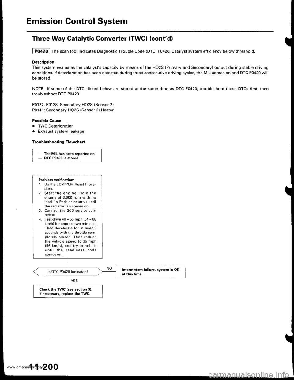
Three Way Catalytic Converter {TWCI (cont'd}
1P0420 Thescantool indicates Diagnostic Trouble Code (DTC) P0420: Catalyst system efficiency belowthreshold.
DescriDtion
This system evaluates the catalyst's capacity by means of the HO2S (Primary and Secondary) output during stable driving
conditions. lf deterioration has been detected during three consecutive driving cycles, the MIL comes on and DTC P0420 will
be stored.
NOTE: lf some of the DTCS listed below are stored at the same time as DTC P0420, troubleshoot those DTCS first. then
troubleshoot DTC P0420.
P0137, P0138: Secondary HO2S (Sensor 2)
P0141: Secondary HO2S (Sensor 2) Heater
Possible Cause
. IWC Deterioration
. Exhaust system leakage
Troubleshooting Flowchart
- The MIL has been reDoried on.- DTC P0420 is stored.
Problem verification:1. Do the ECM/PCM Reset Procedure,2. Start the engine. Hold theengine at 3,000 rpm with noload (in Park or neutrali untilthe radiator fan comes on.3. Connect the SCS service connector.4. Test-drive 40 - 55 mph (64 - 88km/h) for approx. lwo minutes.Then decelerate for at least 3seconds with the throftle completely closed. Then reducethe vehicle speed to 35 mph
156 km/h), and try to hold ituntil the readiness code
Intermittent tailure. system is OKat this time.ls DTC P0420 indicated?
Check the TWC (see section 9).lI nocessary, replace the TwC.
11-200
www.emanualpro.com
Page 431 of 1395
Clutch Pedal
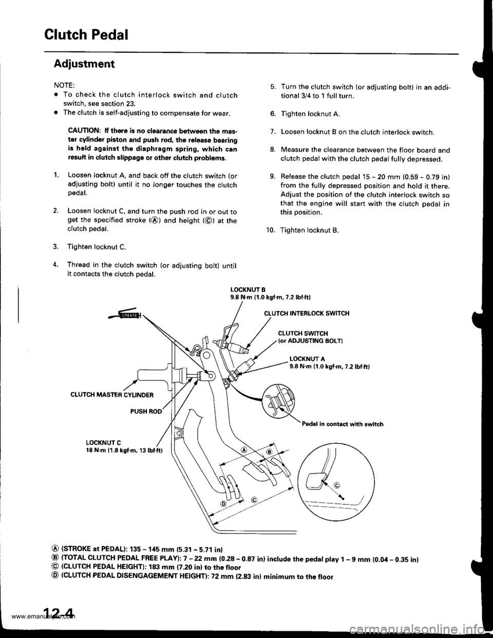
Adiustment
NOTE:
. To check the clutch interlock switch and clutch
switch, see section 23.
. The clutch is self-adjusting to compensate for wear.
CAUTION: lf there is no clearance bstwa‚ā¨n the mas-
ter cylinder piston and push rod, ths roloase bearingis held againsi the diaphragm spring, which canresuh in clutch slippage or other clutch probloms.
1. Loosen locknut A, and back off the clutch switch (or
sdjusting bolt) until it no longer touches the clutchpeoar.
2. Loosen locknut C, and turn the push rod in or out toget the specified stroke (@) and height (@) at theclutch oedal.
3. Tighten locknut C.
4. Thread in the clutch swirch (or adjusting bolt) untilit contacts the clutch oedal.
7.
5.
8.
q
Turn the clutch switch {or adjusting bolt} in an addi-
tional 3/4 to 1 full turn.
Tighten locknut A.
Loosen locknut B on the clutch interlock switch.
Measure the clearance between the floor board and
clutch pedalwith the clutch pedal fully depressed.
Release the clutch pedal 15 - 20 mm (0.59 - 0.79 in)
from the fully depressed position and hold it there,Adjust the position of the clutch interlock switch sothat the engine will start with the clutch pedal in
this position.
Tighten locknut B.10.
LOCKNUT B9.8 N.m 11.0 kgf.m, 7.2 lbf.ftl
CLUTCH INTERLOCK SWITCH
CLUTCH SWTTCH{or ADJUSTING BOLTI
L(rcKNUT A9.8 N.m {1.0 kg{.m,7.2 lbf.ftl
CLUTCH MASTER CYLINDER
PUSH ROD
Pedal in contact with swhch
LOCKNUT C18 N.m (1.8 kgf.m, 13lbtftl
@ {STROKE at PEDAL): 135 - 1its mm (5.31 - 5.71 in}
@ (TOTAL CLUTCH PEDAL FREE PLAY)i7 -22mm (0.28-0.87 in) inctude the pedat ptay 1 - 9 mm (0.0it- 0.35 inl@ (GLUTC,H PEDAL HE|GHTI: ltxt mm (7.20 inl ro rhe ftoor
o (CLUTCH PEDAL DTSENGAGEMENT HEtcHTl: 72 mm {2.txt inl minimum to the floor
\,/a_-_--/
12-4
www.emanualpro.com
Page 443 of 1395
Transfer Assembly
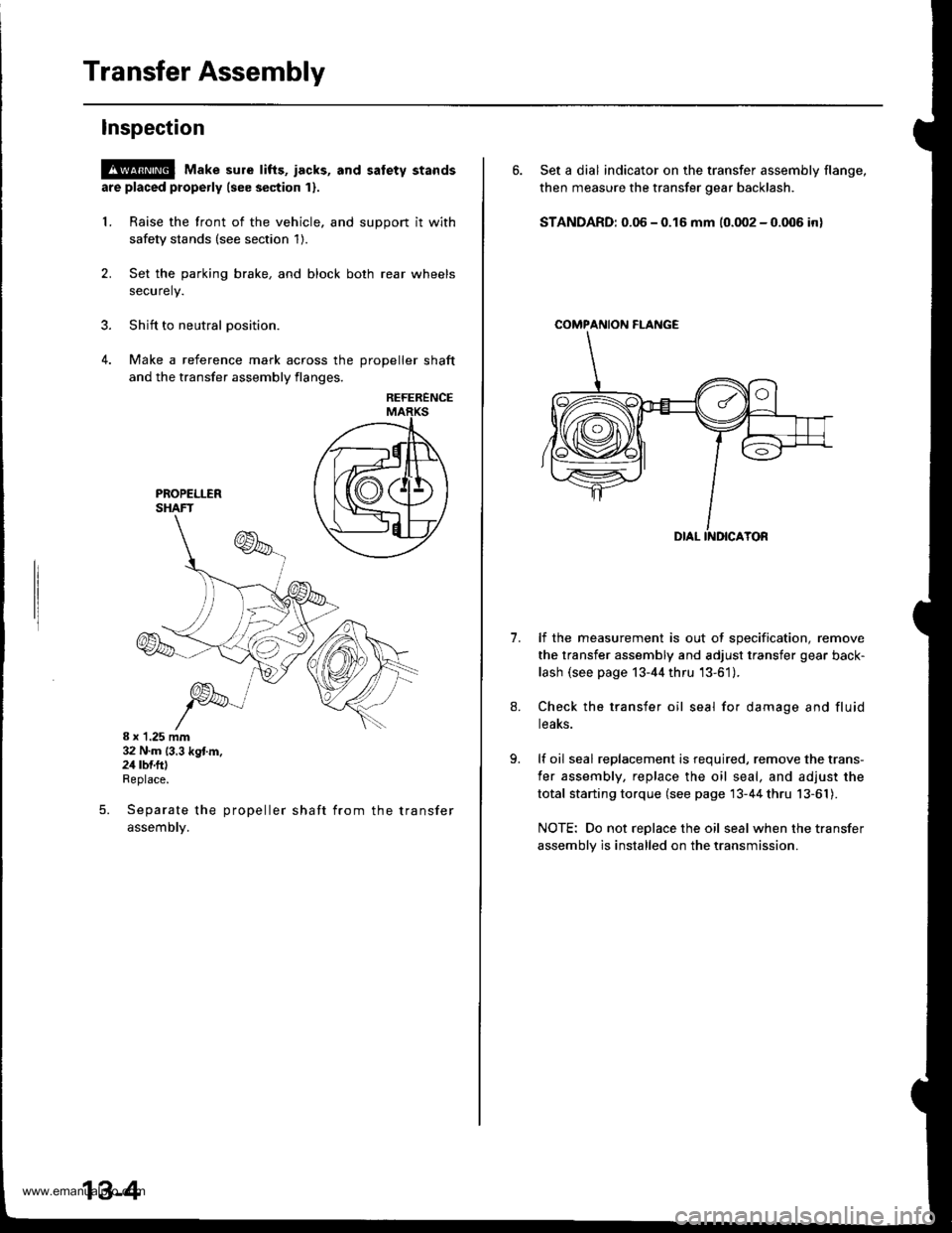
lnspection
@ Make sure tifts, iacks, and satety stands
are placed properly (see section 1).
L Raise the front of the vehicle, and support it with
safety stands (see section 1).
2. Set the parking brake, and block both rear wheels
securely.
3. Shift to neutral oosition.
4. Make a reference mark across the DroDeller shaft
and the transfer assembly flanges,
REFERENCE
8 x 1.25 mm32 N.m (3.3 kg{.m.24 rbf.ftlReplace.
Separate the propeller shaft from the transfer
assemDty.
5.
13-4
6. Set a dial indicator on the transfer assembly flange,
then measure the transfer gear backlash.
STANDARD: 0.06 - 0.16 mm (0.002 - 0.006 in)
COMPAf{ION FI-ANGE
1.lf the measurement is out of specification, remove
the transfer assembly and adjust transfer gear back-
lash (see page 13-44 thru '13-61).
Check the transfer oil seal for damage and fluid
teaKs.
lf oil seal replacement is required, remove the trans-
fer assembly, replace the oil seal, and adjust the
total starting torque (see page 13-44 thru 13-61).
NOTE: Do not replace the oil seal when the transfer
assembly is installed on the transmission.
www.emanualpro.com
Page 444 of 1395
Removal
!@@ Make sure the lifts, i8cks. and safety stands
are placed properly {see section 1}.
1. Raise the front of the vehicle, and support it with
safety stands (see section 1).
2. Set the parking brake, and block both rear wheels
securely.
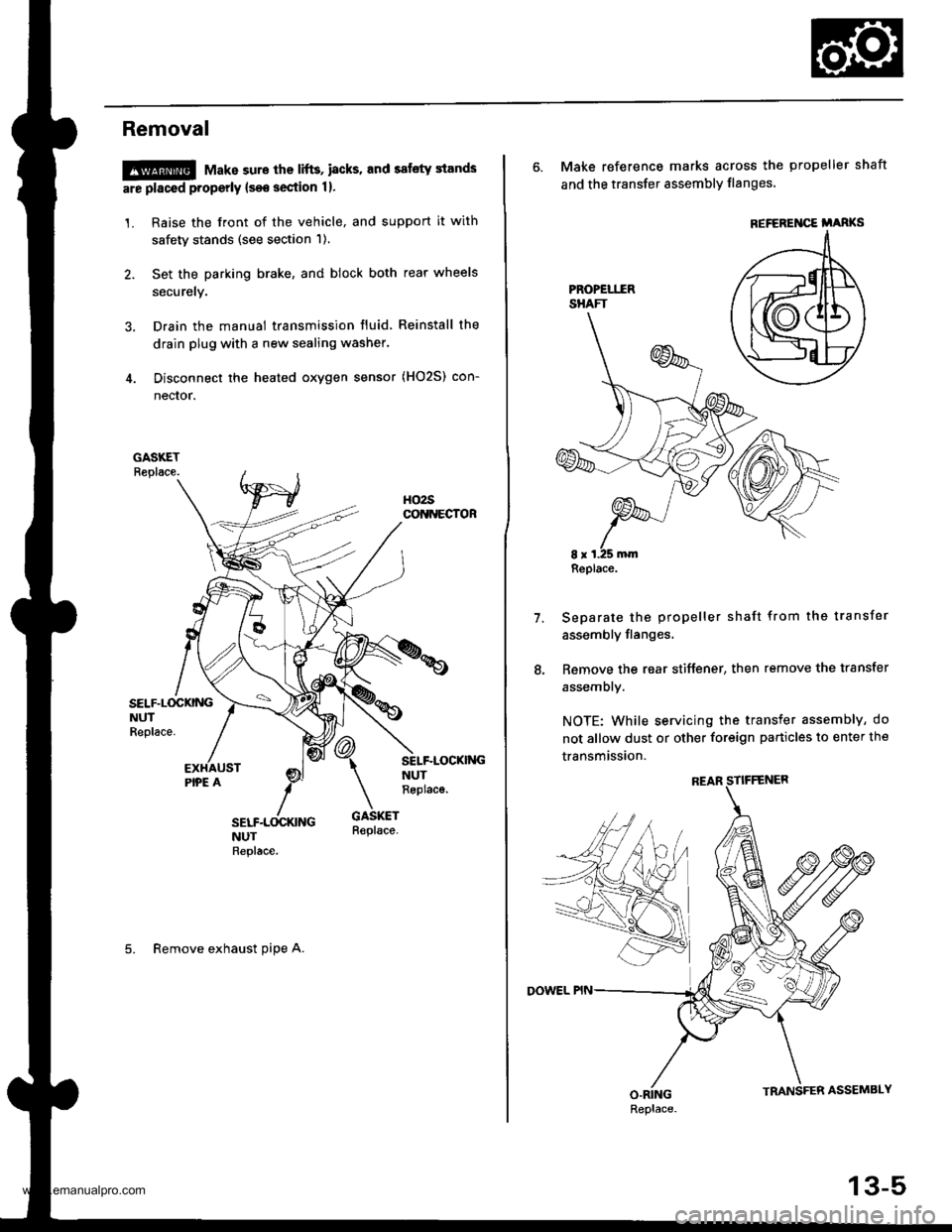
3. Drain the manual transmission fluid Reinstall the
drain plug with a new sealing washer.
4. Disconnect the heated oxygen sensor (HO2S) con-
nector.
SELF.L(rcKNGNUTReplace.
SELF-LOCKI'{GNUTReplac‚ā¨.
5. Remove exhaust oipe A.
6. Make reference marks across the propeller shaft
and the transfer assembly flanges'
Separate the propeller shaft from the transfer
assembly flanges,
Remove the rear stiffener, then remove the transfer
assembly.
NOTE: While servicing the transfer assembly, do
not allow dust or other foreign particles to enter the
transmission.
7.
REFEREI{CE i'ARKS
Replace.
Replace.
13-5
www.emanualpro.com
Page 446 of 1395
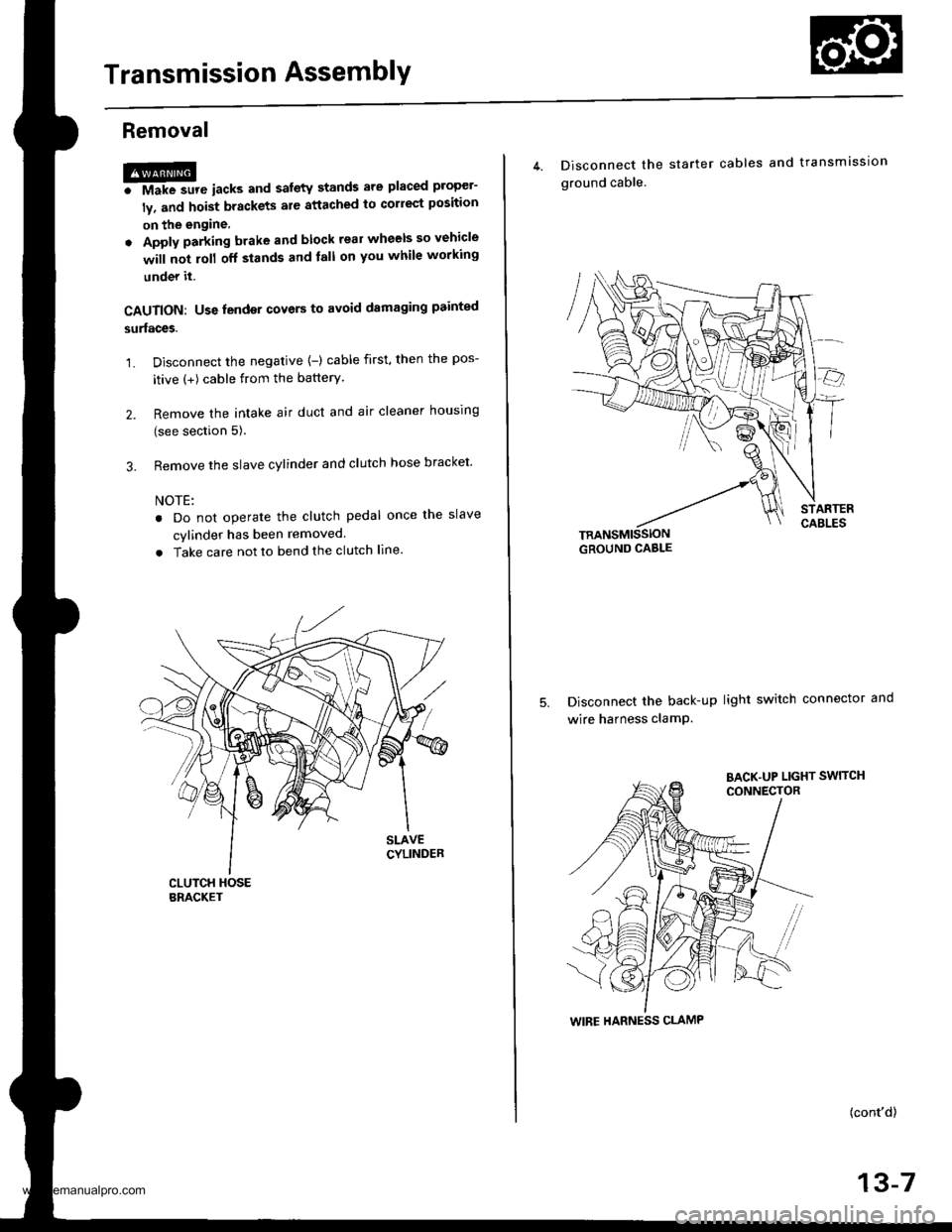
Transmission AssemblY
Removal
@FMak. sw. iack" and safety stands are placed propel-
ly, and hoist brackets are attached to collect position
on the engine,
. Apply parking brake and block rear wheels so vehicle
will not roll off stands and lall on you while working
under it.
CAUTION: Use fender covers to avoid damaging painted
surfaces.
1. Disconnect the negative {-) cable first, then the pos-
itive (+) cable from the batterY.
2. Remove the intake air duct and air cleaner houslng
(see section 5).
3. Remove the slave cylinder and clutch hose bracket'
NOTE:
. Do not operate the clutch pedal once lhe slave
cvlinder has been removed.
. Take care not to bend the clutch line.
4. Disconnect the
ground cable.
starter cables and transmission
TRANSMISSIONGROUND CABLE
Disconnect the back-up light switch connector and
wire harness clamP.
(cont'd)
13-7
WIRE HARNESS CLAMP
www.emanualpro.com
Page 448 of 1395
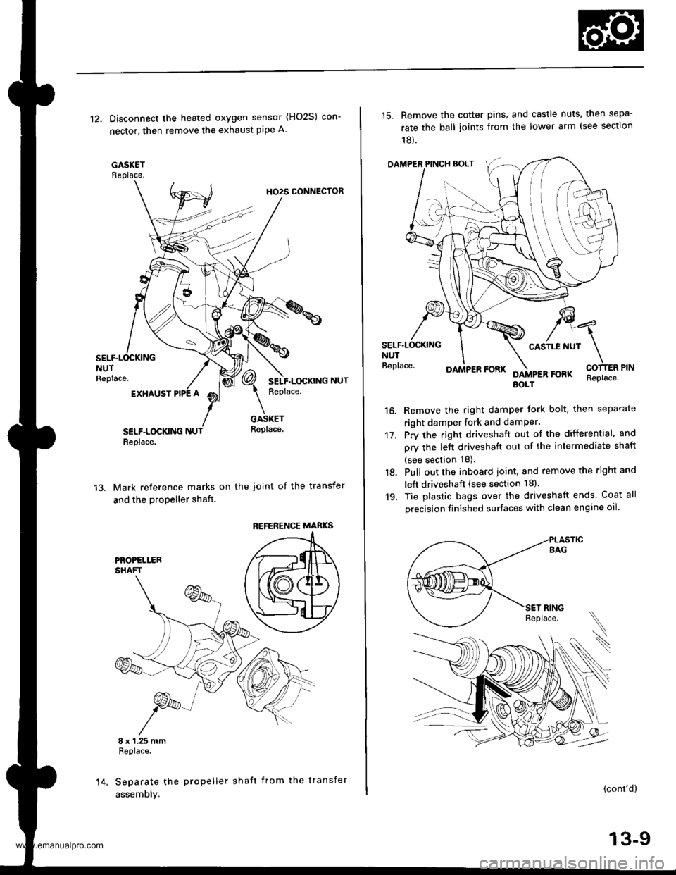
12. Disconnect the heated oxygen sensor (HO2S) con-
nector, then remove the exhaust pipe A.
GASKETReplace.
HO2S CONNECTOR
NUTReplace.
EXHAUST
SELF.LOCKINGReplace.
GASKETReplace.
Mark reference marks on the joint of the transfer
and the propeller shaft.
8 x 1.25 mmReplace.
Separate the propeller shaft from the transfer
assemDly.
REFERENCE MABKS
14.
15. Remove the cotter pins, and castle nuts. then sepa-
rate the ball ioints from the lower arm (see sectlon
18).
OAMPER PINCH BOLT
CASTLE NUTNUTReplace.
17.
16.
DAMPER FORKFOFKEOLTReplace.
Remove the right damper tork bolt, then separate
right damper fork and damPer.
Pry the right driveshaft out of the differential, and
pry the left driveshaft out of the intermediate shaft
(see section 18).
Pull out the inboard ioint, and remove the right and
left driveshaft (see section 18).
Tie plastic bags over the driveshatt ends. Coat all
precision finished surfaces with clean engine oil
18.
19.
\
{cont'd}
13-9
www.emanualpro.com
Page 490 of 1395
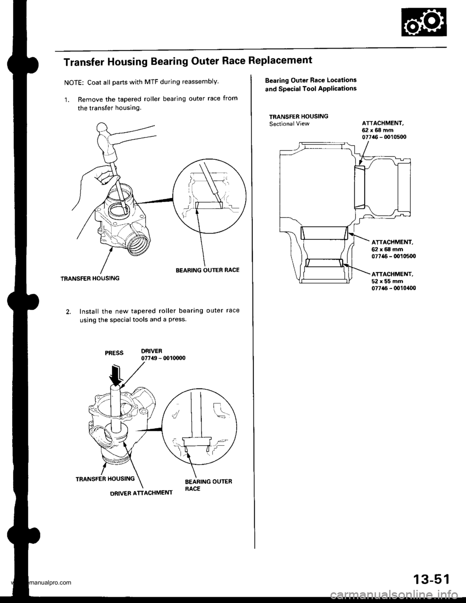
Transfer Housing Bearing Outer Race Replacement
NOTE: Coat all parts with MTF during reassembly.
1. Remove the tapered roller bearing outer race from
the transfer housing.
TBANSFER HOUSING
Install the new tapered roller bearing outer race
using the special tools and a press
DRIVER07749 - 0o1(xD0
TRANSFER HOUSINGBEARING OUTERRACE
J
i=
\l
DRIVER ATTACHMENT
13-51
Bealing Outer Race Locations
and Special Tool APP|ications
TRANSFER HOUSINGSectionalViewATTACHMENT,62x68mm07746 - 0010500
ATTACHMENT,62x68mm07?a6 - 0010500
ATTACHMENT,52x55mm07715 - 0010400
www.emanualpro.com
Page 512 of 1395
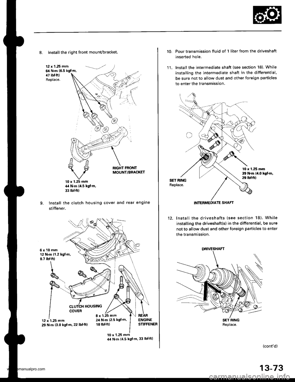
8. Installthe right front mounvbracket.
12 x 1 .25 mm64 N.m (6.5 kgf'm,47 tbf.ftlReplace.
RIGHT FRONTMOUNT/BBACKET
10 x 1.25 mm4,a N.m (4.5 kgf m,
33 tbf ftl
Install the clutch housing cover and rear engine
stiffener.
6xl0mm12 N.m 11.2 kgt.m.8.7 tbf.ft)
HOUSING
'12 x 1.25 mm29 N.m 13.0 kgf.m. 22 lbf'ft)
8 x 1.25 mm24 N.m {2.5 kgf'm'
18 tbl.ft)
10 x 'l .25 mm44 N.m {4.5 kgf m,33 lbf ftl
10. Pour transmission fluid of 1 liter from the driveshaft
inserted hole.
1 1. lnstall the intermediate shaft {see section 18). While
installing the intermediate shaft in the differential.
be sure not to allow dust and other foreign particles
to enter the transmission.
10 r 1.25 mm39 ttm 14.0 kgf.m,29 tbt ftlSET RINGReplace.
12. lnstall the driveshafts (see section 18). While
installing the driveshaft(s) in the differential, be sure
not to allow dust and other foreign panicles to enter
the transmission.
SET RINGReplace.
(cont'd)
13-73
INTERMEOIATE SHAFT
DRIVESHAFT
www.emanualpro.com
Page 515 of 1395
Transmission Assembly
Installation (cont'dl
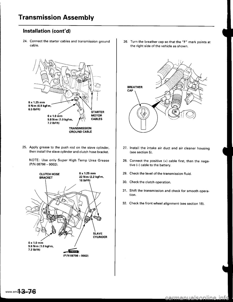
24. Connect the starter cables and transmission ground
caore.
TRANSMISSIONGROUND CABLE
Apply grease to the push rod on the slave cylinder,
then install the slave cylinder and clutch hose bracket,
NOTE: Use only Super High Temp Urea Grease
{P/N 08798 - 9002).
CI-UTCH HOSEBRACKET
8 x 1.25 mm22 N.m 12.2 kgi-m,16 tbr.f0
6x1.0mm9.8 N.m {1.0 kgf.m,7.2 rbf.ftt_G1(P/N 08798
6x1.0mm9.8 N.m (1.0 kg{.m,7.2 tbt.ttl
13-76
- 9002)
26. Turn the breather cap so that the "F" mark points at
the right side of the vehicle as shown.
27. Install the intake air duct and air cleaner housing(see section 5),
28. Connect the positive (+) cable first. then the nega-
tive (-) cable to the battery.
29. Check the level of the transm ission f lu id.
30. Check the clutch operation.
31. Shift the transmission and check for smooth opera-tion.
32. Check the front wheel alignment (see section l8).
www.emanualpro.com
Page 521 of 1395
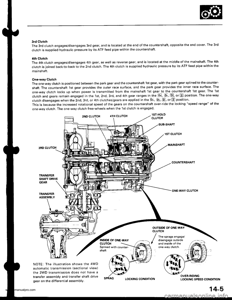
3rd Clutch
The 3rd clutch engages/disengages 3rd gear, and is located at the end of the countershaft, opposite the end cover. The 3rd
clutch is supplied hydraulic pressure by its ATF feed pipe within the countershaft.
ilth Clutch
The 4th clutch engages/disengages 4th gear, as well as reverse gear, and is located at the middle of the mainshaft. The 4th
clutch is joined back-to-back to the 2nd clutch. The 4th clutch is supplied hydraulic pressure by its ATF feed pipe within the
mainshaft.
One-way Clutch
The one-way clutch is positioned between the park gear and the countershaft 1st gear, with the park gear splined to the counter-
shaft. The countershaft 1st gear provides the outer race surface, and the park gear provides the inner race surface The
one,way clutch locks up when power is transmitted from the mainshaft lst gear to the countershaft 1st gear. The 1st
clutch and gears remain engaged in the 1st, 2nd, 3rd, and 4th gear ranges in the lo], pt, E, or E position The one-way
clutch disengages when the 2nd, 3rd, or 4th clutches/gears are applied in the lor, [d, E, or E position'
This is because the increased rotational speed of the gears on the countershaft over-ride the locking "speed range" of the
one-wav clutch. The one-wav clutch free-wheels when the lst clutch is engaged
lST.HOLDCLUTCH
1ST CLUTCH
MAINSHAFT3RD CLUTCH
COUNTERSHAFT
TRANSFERSHAFT DRIVEGEAR
TRANSFERASSEMBLY
NOTE: The illustration shows the 4WD
automatic transmission {sectional view)
the 2WD transmission does not have a
transfer assembly and transfer shaft drive
gear on the differential assembly.
2NO CLUTCH4TH CLUTCH
INSIDE OF ONE.WAYCLUTCH
ONE.WAY CLUTCH
OUTSIDE OF ONE.WAYCLUTCH
The sprags engage/disengage outsideand inside of theSplined with counter- -
shaft
OVER.RIOINGLOCKING SPEED CONOITIONLOCKING CONDITION
14-5,
www.emanualpro.com