Clearance HONDA CR-V 2000 RD1-RD3 / 1.G Repair Manual
[x] Cancel search | Manufacturer: HONDA, Model Year: 2000, Model line: CR-V, Model: HONDA CR-V 2000 RD1-RD3 / 1.GPages: 1395, PDF Size: 35.62 MB
Page 737 of 1395
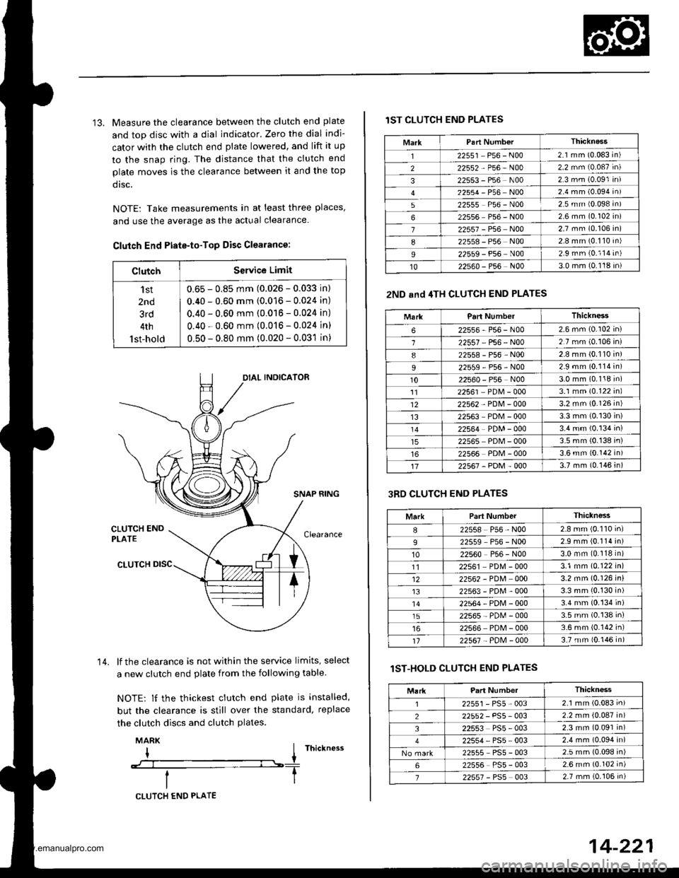
13. Measure the clearance between the clutch end plate
and top disc with a dial indicator. Zero the dial indi-
cator with the clutch end plate lowered, and lift it up
to the snap ring. The distance that the clutch end
plate moves is the clearance between it and the top
dtsc.
NOTE: Take measurements in at least three places'
and use the average as the actual clearance.
Clutch End Ptate-to-Top Disc Clearance:
ClutchService Limit
'l st
2nd
3rd
4th
lst-hold
0.65 - 0.85 mm (0.026 - 0.033 in)
0.40 - 0.60 mm (0.016 - 0.024 in)
0.40 - 0.60 mm (0.016 - 0.024 in)
0.40 - 0.60 mm (0.016 - 0.024 in)
0.50 - 0.80 mm (0.020 - 0.031 in)
SNAP RING
lf the clearance is not within the service limits, select
a new clutch end plate from the following table
NOTE: lf the thickest clutch end plate is installed,
but the clearance is still over the standard, replace
the clutch discs and clutch plates.
MARK
I I rnictness
--:--l----T
14.
CLUTCH END PLATE
14-221
lST CLUTCH END PLATES
2ND and 4TH CLUTCH END PLATES
3RD CLUTCH END PLATES
lST-HOLD CLUTCH END PLATES
MarkThicknass'I22551 P56 - N002.1 mm (0.083 in)
222552-P56-N002.2 mm (0.087 in)
322553 - P56 N002 3 mm (0.091 in)
22554-P56-NOo2.4 mm (0.094 in)
522555 P56 - N002.5 mm {0.098 in)
622556 P56 - N002 6 mm (0.102 in)
722557 - P56 N002.7 mm (0.106 in)
822558 - P56 N002.8 mm (0.110 in)
I22559 - P56 N002.9 rnm (0.114 in)
1022s60 - P56 N003.0 mm (0.118 in)
MarkParl NumberThickness
622556-P56-N002.6 mm (0.102 in)
122557 P56 - N002.7 mm (0.106 in)
822558-P56-N002.8 mm (0.110 in)
22559-P56-N002.9 mm (0.114 in)
1022560 - P56 N003.0 mm (0.118 in)'1122561 PDM - 0003.1 mm (0.122 inl
1222562 - PDM - 0003.2 mm {0.126 in)
1322563 PDM - 0003.3 mm (0.130 in)
22564 PDM - 0003.4 mm (0.134 in)
22565 PDM - 0003.5 mm (0.138 in)
22566 PDM - 0003.6 mm 10.142 in)
1722567-PDM-0003.7 mm (0.146 in)
MarkPart NumberThiclness
I22558 P56 - N002.8 mm (0.110 inl
922559 P56 - N002.9 mm (0.114 in)
1022560 P56 - N003.0 mm (0.118 in)
1122561 PD[4 - 0003.1 mm (0.122 in)
1222562 - PDM 0003.2 mm (0.126 in)
t322563-PDM-0003.3 mm (0.130 in)'1422564-PDN4-0003.4 mm (0.134 in)
1522565-PD[,l-0003.5 mm (0.138 in)
22566 PDM - 0003.6 mm (0.142 in)'t122567 - PoM - 0003.7 mm {0.146 in)
Thickness
2255r-PS5-0032.1 mm (0.083 in)
22552 - PS5- 0032.2 mm {0.087 in)
322553 PS5 - 0032.3 mm (0.091 in)
22554, PS5 - 0032.4 mm (0.094 in)
22555 PS5 - 0032.5 mm (0.098 in)
622556 PS5 - 0032.6 mm {0.102 in)
722557 - PSs 0032.7 mm (0.106 in)
www.emanualpro.com
Page 742 of 1395
Differential
Side Clearance Inspection
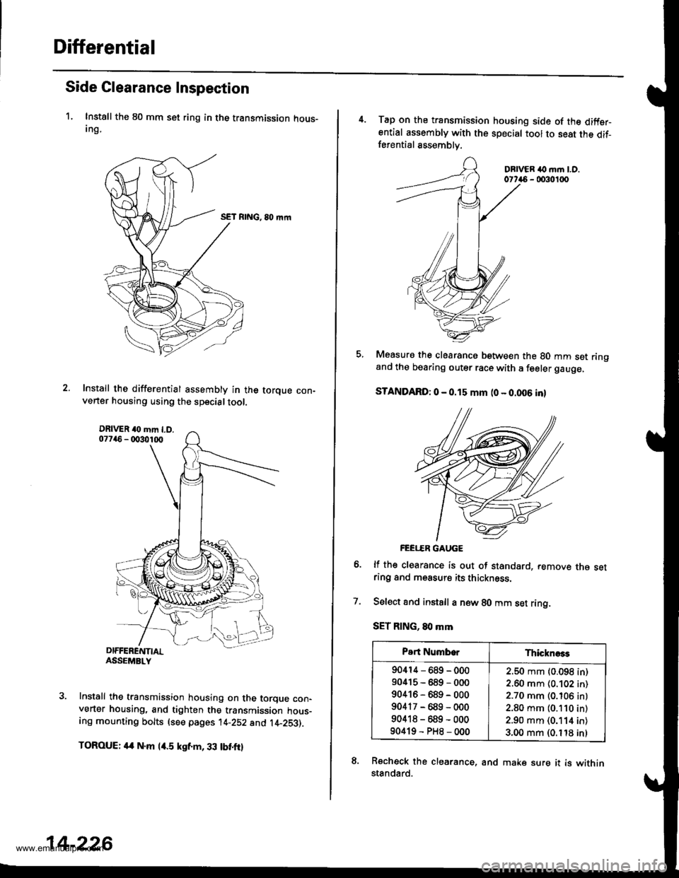
1. Instsll the 80 mm set ring in the transmission hous-Ing,
SET RING, 80 mrn
Install the differential assembly in the torque con-verter housing using the specialtool.
Install the transmission housing on the torque con-verter housing, and tighten the transmission hous-ing mounting bolts (see pages 14-252 and t4-253).
TOROUE: 4a N.m l/r.5 kgf.m, 33 tbt.ftl
14-226
4. Tap on the transmission housing side of the diffsrential assembly with the special tool to seat the dif-ferential assemblv.
DBIVER ilo m.n LO.0t746 - 0030100
Measure the clearancs between the 80 mm set ringand the bearing outer race with a feeler gauge,
STANDARD: 0 - 0.15 mm (0 - 0.006 inl
FEEI..ER GAUGE
lf the clearance is out of standard, remove rne setring and measurs its thickness.
Select and instsll a new 80 mm set ring.
SET RING, 80 mm
Recheck the clearance, and make sure it is withinstandard.
7.
Part NumborThicknoss
90414-689-000
90415-689-000
90416-689-000
90417-689-000
90418-689-000
90419-PH8-000
2.50 mm (0.098 in)
2.60 mm (0.102 in)
2.70 mm (0.106 inl
2.80 mm (0.110 in)
2.90 mm (0.114 in)
3.00 mm (0. t'18 inl
www.emanualpro.com
Page 785 of 1395
Disassembly/Reassembly -'99 - 00 Models
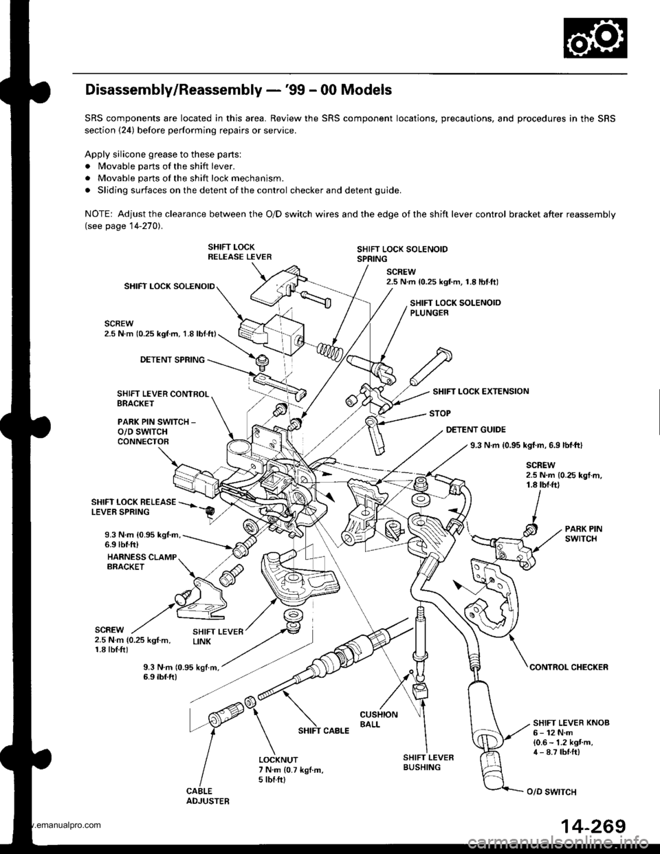
SRS components are located in this area. Review the SRS component locations, precautions, and procedures in the SRS
section (24) before performing repairs or service.
Apply silicone grease to these parts:
. Movable parts of the shift lever.
. Movable parts of the shift lock mechanism.
. Sliding surfaces on the detent of the control checker and detent guide.
NOTE: Adjustthe clearance between the O/D switch wires and the edge ofthe shift lever control bracket after reassembly(see page 14-270).
SHIFT LOCKRELEASE LEVERSHIFT LOCK SOLENOIDSPRING
SCREW2.5 N.m {0.25 kgf.m, 1.8lbtft)SHIFT LOCK SOLENOID
SCREW2.5 N.m (0.25 kgl.m, 1.8 lbl.ft)
SHIFT LOCK SOLENOIOPLUNGER
DETENT SPRING
SHIFT LEVER CONTROLBRACKET
PARK PIN SWITCH _
o/D swtTcHCONNECTOB
SHIFT LOCK EXTENSION
STOP
DETENT GUIDE
9.3 N.m {0.95 kgf.m, 6.9 lbl.ftl
SCREW2.5 N.m {0.25 kgt m,1.8 tbf.ftl
SHIFT LOCK BELEASELEVER SPRING
9.3 N.m {0.95 kgl.m,6.9 lbtfr)
HARNESS CLAMPERACKET
PARK PINswrTcH
SCREW2.5 N.m {0.25 kgf.m,1.8 tbl.f0
9.3 N.m 10.95 kgtm,6.9 tbf.ft)CONTROL CHECKER
SHIFT LEVER KNOB6- 12 N.m{0.6 - 1.2 kgt'm,4 - 8.7 tbnft)LOCKNUT7 N.m {0.7 kgl.m,5 tbf.ftl
SHIFT LEVERBUSHING
o/D swtTcH
14-269
www.emanualpro.com
Page 786 of 1395
Shift Lever
Over-Drive (O/Dl Switch Wire Clearance Adjustment -'99 - 00 Models
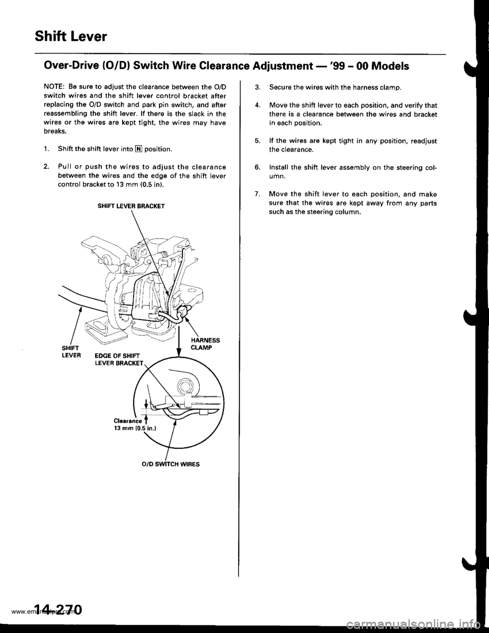
NOTE: Be sure to adjust the clearance between the O/D
switch wires and the shift lever control bracket after
replacing the O/D switch and park pin switch, and after
reassembling the shift lever. lf there is the slack in the
wires or the wires are kept tight, the wires may have
Dreaks.
1. Shift the shift lever into E positron.
2. Pull or push the wires to adjust the clearance
between the wires and the edge of the shift lever
control bracket to 13 mm (0.5 in).
SHIFT LEVER BRACKET
14-270
7.
Secure the wires with the harness clamp.
Move the shift lever to each position, and verify that
there is a clearance between the wires and bracket
in each position.
lf the wires are kept tight in any position, read.iust
the clearance.
Install the shift lever assembly on the steering col-
umn.
Move the shift lever to each position, and make
sure that the wires are kept away from any parts
such as the steering column.
www.emanualpro.com
Page 829 of 1395
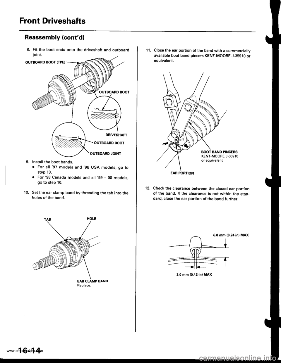
Front Driveshafts
8. Fit the boot ends onto the driveshaft and outboard
lornt.
OUTBOARD BOOT fiPE)
OUTBOARD BOOT
OUTBOARD BOOT
Reassembly (cont'd)
Install the boot bands,
. For all '97 models and'98
step 13.
. For'98 Canada models andgo to step 10.
OUTBOARD JOINT
USA models, go to
all '99 - 00 models,
10. Set the ear clamp band by threading the tab into theholes of the band.
16-14
11. Close the ear portion of the band with a commercially
available boot band pincers KENT-MOORE J-35910 or
equivalent.
BOOT BAND PINCERSKENT.MOORE J-35910or equivalent
12.Check the clearance between the closed ear Dortionof the band, lf the clearance is not within the stan-dard, close the ear portion of the band further.
6.0 mm 10.24 in) MAX
3.0 mm {0.12 in} MAX
EAR PORTION
www.emanualpro.com
Page 876 of 1395
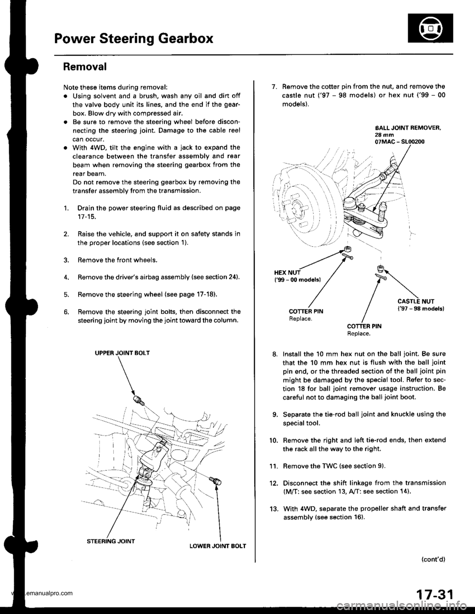
Power Steering Gearbox
Removal
Note these items during removal:
. Using solvent and a brush, wash any oil and dirt off
the valve body unit its lines, and the end if the gear-
box. Blow dry with compressed air.
. Be sure to remove the steering wheel before discon-
necting the steering joint. Damage to the cable reel
can occur.
. With 4WD. tilt the engine with a jack to expand the
clearance between the transfer assembly and rear
beam when removing the steering gearbox from the
rear oeam.
Do not remove the steering gearbox by removing the
transfer assembly from the transmission.
1. Drain the power steering fluid as described on page'17-15.
Raise the vehicle, and suppon it on safety stands in
the proper locations (see section 1).
Remove the front wheels,
Remove the drive/s airbag assembly {see section 24).
Remove the steering wheel {see page 17-18).
Remove the steering joint bolts, then disconnect the
steering joint by moving the joint toward the column.
UPPER JOINT BOLT
LOWER JOINT BOLT
13.
7. Remove the cotter pin from the nut, and remove the
castle nut {'97 - 98 models) or hex nut ('99 - 00
models).
COTTER PINReplace.
Install the 10 mm hex nut on the ball joint. Be sure
that the 10 mm hex nut is flush with the ball joint
pin end, or the threaded section of the ball joint pin
might be damaged by the special tool. Refer to sec-
tion 18 for ball joint remover usage instruction, Be
careful not to damaging the ball joint boot.
Separate the tie-rod ball joint and knuckle using the
special tool.
Remove the right and left tie-rod ends, then extend
the rack all the way to the right.
Remove the TWC (see section 9).
Disconnect the shift linkage from the transmission
(M/T: see section 13, A/T: see section 14).
With 4WD. separate the propeller shaft and transfer
assembly (see section 161.
10.
11.
(cont'd)
17-31
www.emanualpro.com
Page 879 of 1395
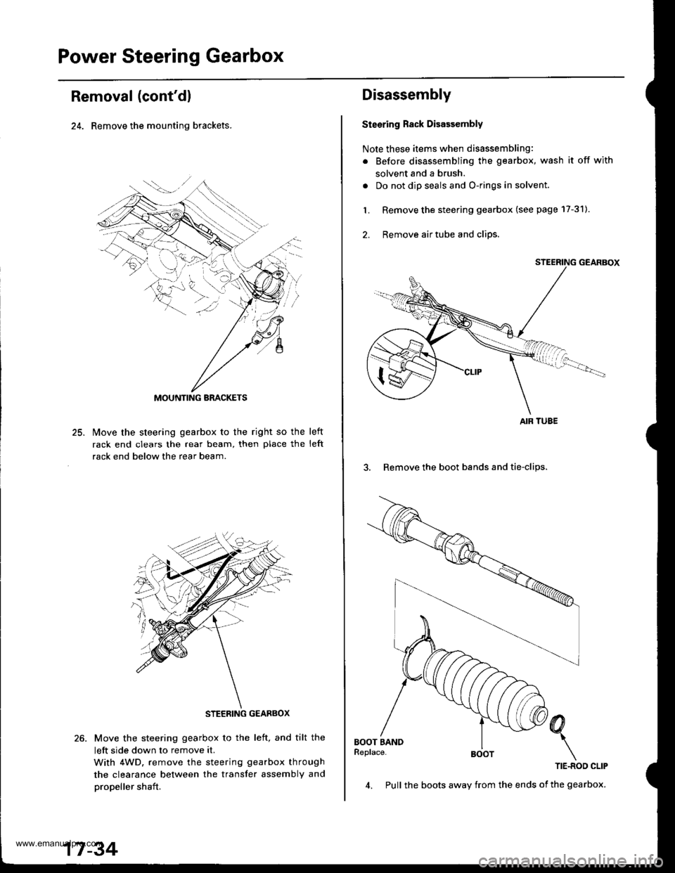
Power Steering Gearbox
Removal (cont'dl
24. Remove the mounting brackets.
25.lvlove the steering gearbox to the right so the
rack end clears the rear beam, then place the
rack end below the rear beam.
left
left
Move the steering gearbox to the left, and tilt the
left side down to remove it.
With 4WD. remove the steering gearbox through
the clearance between the transfer assembly and
propeller shaft.
MOUNTING BRACKETS
STEEBING GEARBOX
17 -34
4. Pull the boots away from the ends of the gearbox.
Disassembly
Steering Rack Disassembly
Note these items when disassembling:
. Before disassembling the gearbox, wash it off with
solvent and a brush.
. Do not dip seals and O-rings in solvent.
1. Remove the steering gearbox (see page 17-31).
2. Remove airtube and clips.
3. Remove the boot bands and tie-clips.
AIR TUBE
www.emanualpro.com
Page 892 of 1395
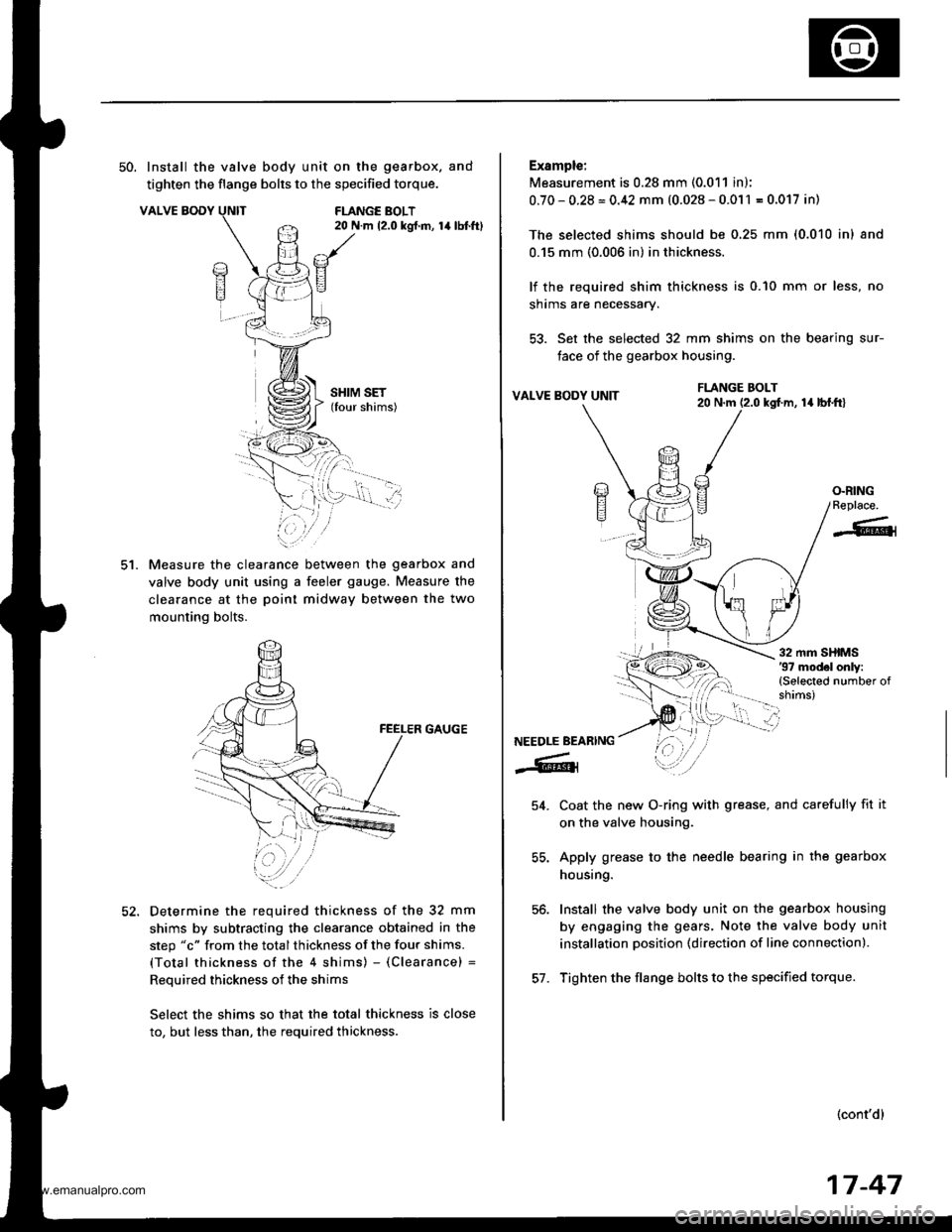
50. Install the valve body unit on the gearbox. and
tighten the flange bolts to the specified torque.
VALVE BODYFLANGE BOLT20 N.m 12.0 kgt.m, 14lbtft)
ct.
SHIM SET(four shims)
Measure the clearance between the gearbox and
valve body unit using a feeler gauge. Measure the
clearance at the poinl midway between the two
mounting bolts.
GAUGE
Determine the required thickness of the 32 mm
shims by subtracting the clearance obtained in the
step "c" from the total thickness of the four shims.
(Total thickness of the 4 shims) - (Clearance) =
Reouired thickness of the shims
Select the shims so that the total thickness is close
to, but less than, the required thickness.
Example:
Measurement is 0.28 mm (0.011 in);
0.70-0.28=0.42 mm (0.028-0.011 = 0.017 in)
The selected shims should be 0,25 mm (0.010 inl and
0.15 mm (0.006 in) in thickness.
lf the required shim thickness is 0.10 mm or less, no
shrms are necessary.
53. Set the selected 32 mm shims on the bearing sur-
face of the gearbox housing.
VALVE BODY UNITla lbl.frl
Coat the new O-ring with grease, and carefully fit it
on the valve housing.
Apply grease to the needle bearing in the gearbox
housing.
Install the valve body unit on the gearbox housing
by engaging the gears. Note the valve body unit
installation position (direction of line connection).
Tighten the flange bolts to the specified torque.
(cont'd)
FLANGE BOLT20 N.m (2.0 kgf.m,
/a)E?
E
O.RINGReplace.
-6{
NEEDLE BEARING
-6lr
54.
56.
57.
17-47
www.emanualpro.com
Page 925 of 1395
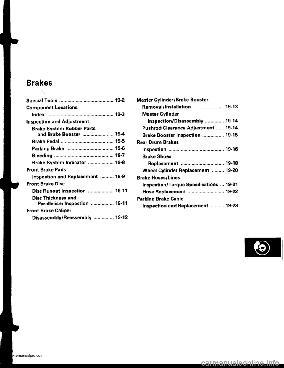
Brakes
Special Tools ............. 19-2
Component Locations
lndex ................ ...... 19-3
Inspection and Adlustment
Brake System Rubber Parts
and Brake Booster ..........,,,.......... 19-4
Brake Pedal ............ 19-5
Parking Brake ........ 19-6
Bleeding ................. 19'7
Brake System Indicator ................... 19-8
Front Brake Pads
Inspection and Replacement .......... 19-9
Front Brake Disc
Disc Runout Inspection ................... 19-11
Disc Thickness and
Parallelism Inspection ........,........ 19-1 1
Front Brake Caliper
Disassembly/Reassembly ............... 19-12
Master Cylinder/Brake Booster
Removal/lnstallation ....................... 19-13
Master Cylinder
Inspection/Disassembly .............. 19-14
Pushrod Clearance Adiustment ...... 19-14
Brake Booster Inspection ...,.,,,,....... 1 9-1 5
Rear Drum Brakes
Inspection .............. 19-15
Brake Shoes
Replacement ..... 19-r 8
Wheel Cylinder Replacement ......... 19-20
Brake Hoses/Lines
Inspection/Torque Specifications ... 19-21
Hose Replacement ....,...,............. ..,,, 19-22
Parking Brake Cable
Inspection and Replacement .......... 19-23
www.emanualpro.com
Page 927 of 1395
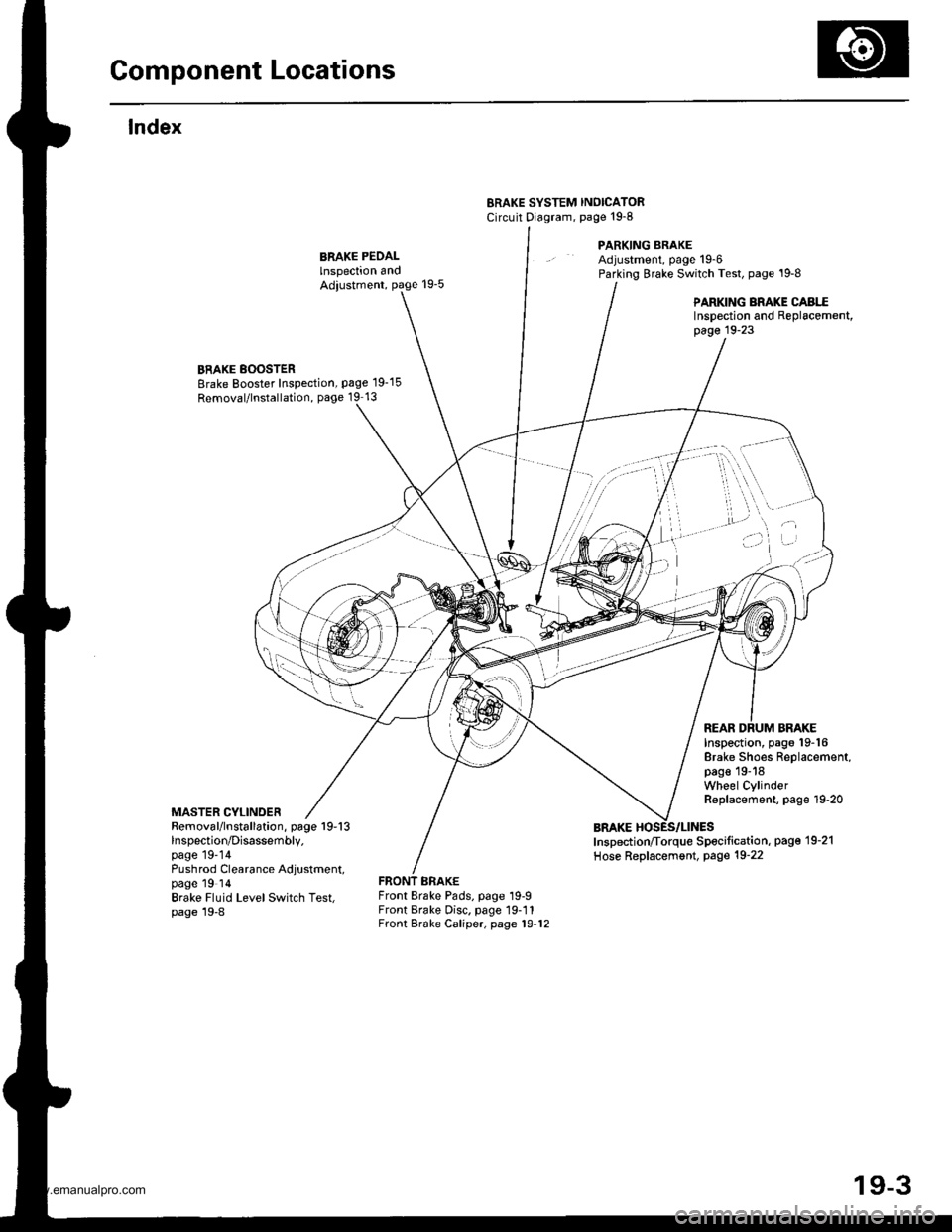
Gomponent Locations
lndex
ERAKE SYSTEM INOICATORCircuit Diagram, page't9-8
PARKING BRAKEAdjustment, page 19-6Parking Brake Switch Test, page '19-8
PARKING BRAKE CABI..EInspection and Replacement,page 19-23
BRAKE BOOSTERBrake Booster Inspection, page 19-15
Removal/lnstallation, page 19 13
MASTER CYLINDER
Inspection, pago 19-16Brake Shoes Replacement,page 19-18Wheel CylinderReplacement, page 19-20
REAR DRUM BRAKE
Removal/lnstallation, page 19-13lnspection/Disassembly.page 19-14Pushrod Clearance Adjustment,page 19 ldBrake Fluid LevelSwitch Test,page 19-8
Inspection/Torque Specification, pag€'19-21
Hose Replacement, Page 19-22
Front Brake Pads, page 19-9Front Brake Disc. page 19-11Front Brake Caliper, page 19-12
)i't ' -"''
/'"''t,'..,1 ...,. , \,,,.
i ,.'
'a.,
I
.) ..)
t ^fl)
19-3
www.emanualpro.com