Fill atf HONDA CR-V 2000 RD1-RD3 / 1.G Workshop Manual
[x] Cancel search | Manufacturer: HONDA, Model Year: 2000, Model line: CR-V, Model: HONDA CR-V 2000 RD1-RD3 / 1.GPages: 1395, PDF Size: 35.62 MB
Page 41 of 1395

Lubrication Points
For the details of lubrication points and type of lubricants to be applied. refer to the illustrated index and various work pro-
cedures (such as Assembly/Reassembly, Replacement, Overhaul, Installation, etc.) contained in each section.
Recomm6nded Engine OilEngine oil viscosity for ambient temperature ranges
100'F
-30 -20 .10 0 10 20 30 40'c
r1: Always use Genuine Honda Manual Transmission Fluid {MTF). Using motor oil can cause stiffer shifting because it
does not contain the orooer additives.*2: Always use Genuine Honda Premium Formula Automatic Transmission Fluid (ATF). Using a non-Honda ATF can affect
shift qualitv.+3r Always use Genuine Honda DOT 3 Brake Fluid. Using a non-Honda brake fluid can cause corrosion and decrease the
life of the system.*4: Always use Genuine Honda Power Steering Fluid. Using any other type of power steering fluid or automatic transmis-
sion fluid can caused increased wear and poor steering in cold weather.
API SERVICE LABEL
/,.*-G\
/.'z-\e\t/6AE\ll-;-1 5w-30 /---l
w
API CERTIFICATION SEAL
ffi-20 0 20
NO.LUBRICATION POINTSLUBRICANT
EngineAPI Service Grade: Use SJ "Energy Conserving" grade oil. The oilcontainer may also display the API Certitication seal shownbelow. Make sure it says "For Gasoline Engines." SAE vjscosity:See chart below.
2
TransmissionManualGenuine Honda MTF*1
AutomaticGenuine Honda Premium Formula Automatic Transmission Fluid(ATF)*'
3Rear differentialGenuine Honda CVT Fluid
4Brake line (includes ABS line)Genuine Honda DOT 3 Brake Fluid*3
5Clutch LineBrake fluid DOT 3 or DOT 4*3
6Shift lever pivots (Manual transmission)Grease with molybdenum disultide
1Release fork (Manual transmission)LJrea Grease UM264 P/N 4'1211 - PYs - 305
IPower steering gearboxSteering grease P/N 08733 - B070E
Throttle cable end {Dashboard lower panel holelSilicone grease
10l112
14
Throttle cable end (Throttle link)Brake master cylinder pushrodPedal linkageBattery terminalsFuelfill lidClutch master cylinder pushrod
Multi purpose grease
1617181920
Hood hinges and hood lockTailgate hingesHatch glass hingesDoor hinges, upper and lowerDoor opening detent
Honda White Lithium Grease
21
22
Caliper Piston seal, Dust seal,Caliper pin, PistonShilt cable and select cable {Manual transmission)Silicone grease
23Brake line ioints (Front and rear wheelhouse)Rust preventives
24Power steering systemGenuine Honda Power Steering Fluid-.
25Air conditioning compressorCompressor oil: SP 10 lP/N 38897 - P13 - A0lAH or38899-P13-A01)For Refrigerant: HFC 134a (R,134a)
3-2
www.emanualpro.com
Page 190 of 1395
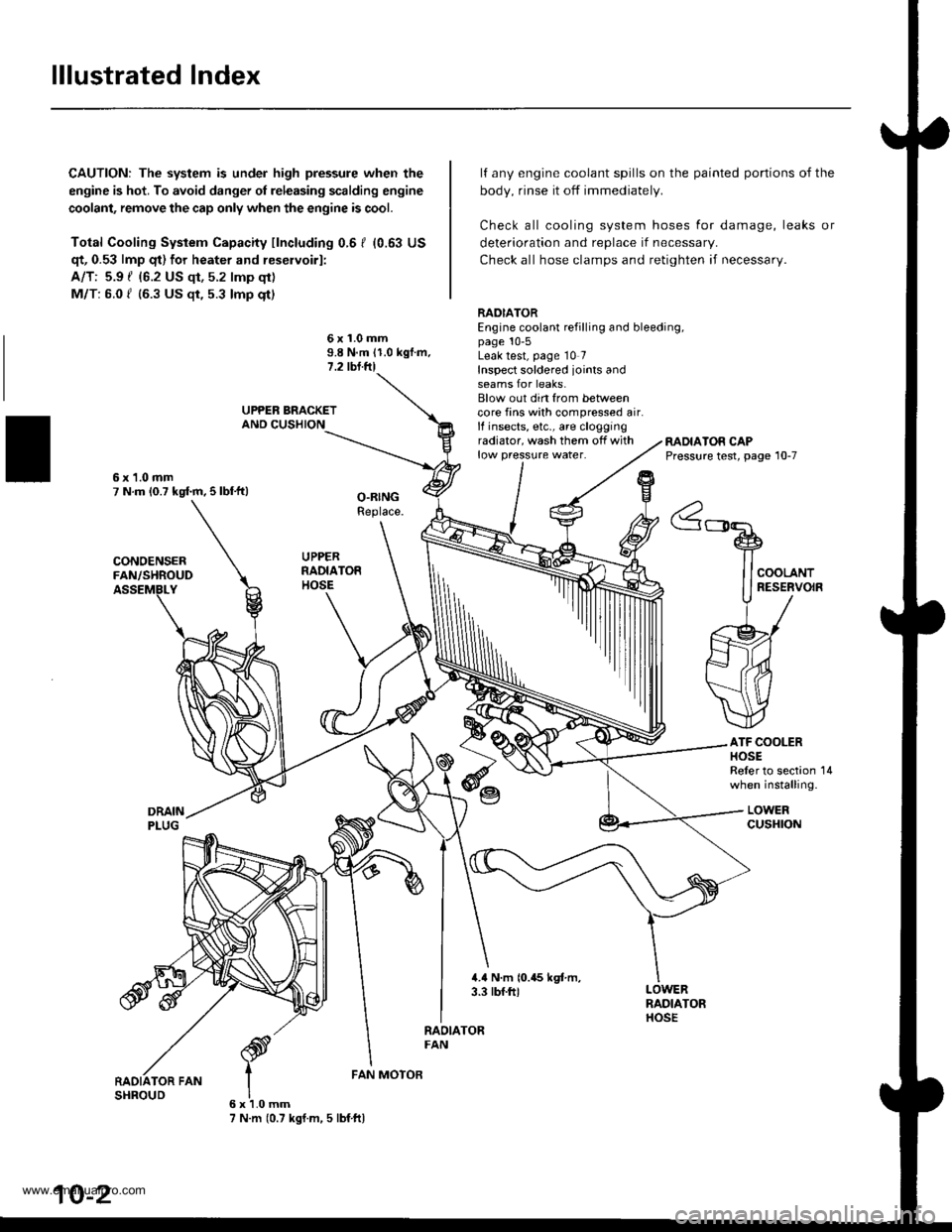
lllustrated Index
CAUTION: The system is under high pressure when the
engine is hot. To avoid danger ol releasing scalding engine
coolant, remove the cap only when the engine is cool.
Total Cooling System Capacity fincluding 0.6 I (0.63 US
qt, 0.53 lmp qt) for heater and reservoirl:
A/T: 5.9 { {6.2 US qt, 5.2 lmp qt)
M/T: 6.0 f (6.3 US $, 5.3 lmp qt)
deterioration and replace if necessar,.
Check all hose clamps and retighten if necessary.
lf any engine coolant spills on the
body, rinse it off immediately.
Check all cooling system hoses
painted portions of the
for damage, leaks or
6x1.0mm9.8 N.m 11.0 kgf.m.1.2 tbl.ftl
RADIATOREngine coolant refilling and bleeding,page 10-5Leak test, page 10 7Inspect soldered joints andseams for leaks.Blow out din from betweencore fins with compressed air.lf insects, etc., are cloggingradiator, wash them off withlow pressure water.RADIATOR CAPPressure test, page 10-7
ATF COOLERHOSEReler to section 14when installing.
LOWERcusHroN
6x1.0mm7 N.m (0.7 kgf.m, 5 lbf ftl
FAN MOTOR
10-2
www.emanualpro.com
Page 192 of 1395
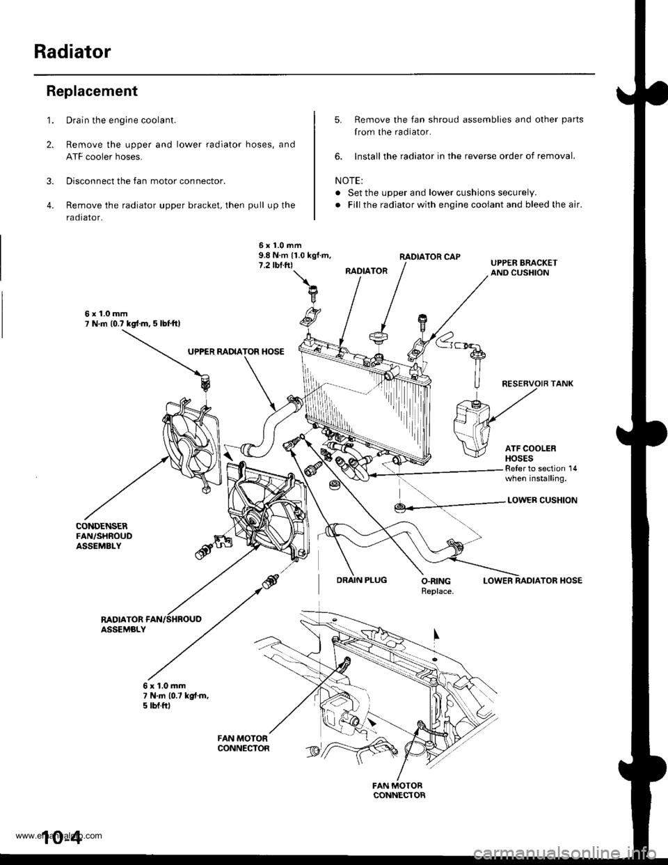
Radiator
1.
2.
3.
4.
Replacement
CONDENSERFAN,/SHROUDASSEMBLY
Drain the engine coolant.
Remove the upper and lower radiator hoses, and
ATF cooler hoses.
Disconnect the fan motor connector.
Remove the radiator upper bracket, then pull up the
raotalor,
5. Remove the fan shroud assemblies and other parts
from the radiator.
6. lnstall the radiator in the reverse order of removal.
NOTE:
. Set the upper and lower cushions securely.
. Fill the radiator with engine cooiant and bleed the air.
RADIATOR CAP
RADIATOR
6x1.0mm9.8 N.m 11.0 kgf.m,7.2 tbl.trl
6x1.0mm7 N.m (0.? kgd.m, 5 lbl.ftl
UPPER MDIATOR HOSE
Reler to section 14when installing.
DRAIN PLUG
LOWER CUSHION
LOWERTOR HOSE
RADIATORASSEMBLY
6x1.0mm7 N.|n 10.7 kgt.m,5 tbt.ftl
rriItriiii
10-4
www.emanualpro.com
Page 676 of 1395
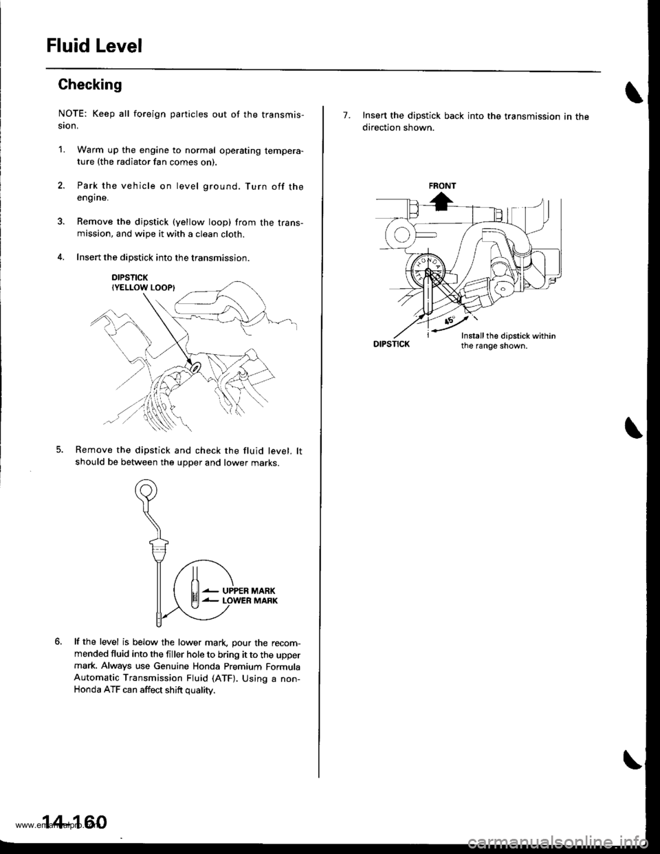
Fluid Level
Checking
NOTE: Keep all foreign particles out of the transmis-
ston,
1. Warm up the engine to normal operating tempera-ture (the radiator fan comes on)
Park the vehicle on level ground. Turn off theengine.
Remove the dipstick (yellow loop) from the trans-mission, and wipe it with a clean cloth.
Insert the dipstick into the transmission.
DIPSTICK
Remove the dipstick and check the fluid level. lt
should be between the upper and lower marKs.
lf the level is below the lower mark. pour the recom-mended fluid into the filler hole to bring it to the uppermark, Always use Genuine Honda Premium FormulaAutomatic Transmission Fluid (ATF). Using a non-Honda ATF can affect shift oualitv.
lt
El--
UPPERMARKMARK
14-160
7. Insert the dipstick back into the transmission in the
direction shown.
DIPSTICK
FRONT
-'-Y'
Insrall the dipstick within
www.emanualpro.com
Page 677 of 1395

Pressure Testing
Changing
NOTE: Keep all foreign particles out of the transmis-
sion.
1. Bring the transmission up to operating temperature
(the radiator fan comes on) by driving the vehicle.
Park the vehicle on level ground. turn the engane
off. then remove the drain Plug.
NOTE: lf a cooler flusher is to be used, see page
14-264 and 14-265.
TRANSMISSIONEND COVER
DRAIN18 x 1.5 mmSEALING WASHEBReplace.49 N.m {5.0 kgt.m, 36 lbf.tl)
Reinstall the drain plug with a new sealing washer,
then refill the transmission with the recommended
fluid to the uDper mark on the dipstick. Always use
Genuine Honda Premium Formula Automatic
Transmission Fluid (ATF) Using a non-Honda ATF
can affect shift quality.
Automatic Transmission Fluid Capacity:
4WD;
2.9 { (3.1 US qt. 2.6 lmp qt) 8t change
5.8 ? {7.2 US $, 6.0 lmp qt} at ovethaul
2WD:
2.7 | l2.S US qt,2.1lmp qtl ai change
5.9 ? {6.2 US $, 5.2 lmp qtl at ovolhaul
2.
a
a
1.
Wlrile testing, be careful of the rotaling wheols.
Mako sure lifts, iacks, and safety stands ar€ placed
properly (see scction 11.
Before testing, be sure the transmission fluid is
filled to the proPer level.
4WD:
Raise the vehicle (see section 11.
2WD:
Raise the front of the vehicle, and make sure it is
securely supported. Set the parking brake, and block
both rear wheels securely.
Allow all four wheels {4WD) or front wheels (2wD}
to rotate freely.
Warm up the engine (the radiator fan comes on),
then stop it and connect the tachometer.
Connect the oil pressure gauges to each inspection
hole securely, and do not allow dust or other foreign
particles to enter the inspection holes.
TOROUE: 18 N'm ll.8 kgf'm, 13 lbf'ft)
5.
A/T PRESSURE HOS€,2210 mm07MAJ - PYiOllA
{4 Requircd}
,4'/"' ,a
W'
A/T PRESSURE HOSEADAPTER07MAJ - PYt0120(il Rcquiledl
6. Measure the following Pressure:. Line Pressure ..........,14-162
. 1st. 1st-hold Clutch Pressure .............'. 14-162
. 2nd,3rd and 4th Clutch Pressure .......... 14-163
7. Install new sealing washers and the sealing bolts in
the inspection holes, and tighten to the specified
toroue.
(cont'd)
A/T OIL PRESSUREGAUGE SET W/PANEL07{06 - 0020400
/4\\-J-- (
+..\.-.\-'-\
A/T LOW PBESSUREGAUGE w/PANEL07406 - 0070300
TOROUE: 18 N'm 11.8 kgf'm, 13 lbf'ft)
14-161
www.emanualpro.com
Page 684 of 1395
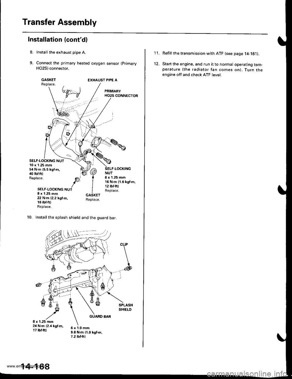
Transfer Assembly
Installation (cont'dl
Install the exhaust pipe A.
Connect the primary heated oxygen sensor (Primary
H02S) connector,
GASKETReplace.EXHAUST PIPE A
SELF.LOCKING NUT10 x 1.25 mm54 N.m {5.5 kgf.m,40 rbf.ft)Replace.
NUT8 x 1.25 mm16Nm11.6kgf.m,12 lbf.fOReplace.
-LOCKING
SELF-LOCKING NUT8 x 1.25 mm22 N.m (2.2 kgl.m,16 rbr.fttReplace.
10. Installthe splash shield and the guard bar.
6x1.0mm9.8 N.m {1.0 kgt.m,7.2 tbt.ftt
14-168
'I '�I.
12.
Refillthe transmission with ATF (see page 14-161).
Start the engine, and run it to normal operating tem-perature (the radiator fan comes on), Turn theengine off and check ATF level.
www.emanualpro.com
Page 779 of 1395

26. Connect the vehicle speed sensor (VSS). the coun-
tershaft speed sensor. and the A,/T gear position
switch connectors,
VEHICLE SPEEO
SPEED SENSOACO'{NECTOR
Connect the lock-up control solenoid valve connec-
tor, then install the harness clamp on the clamp
bracket.
HARNESS CI-AMP
27.
RADIATOR HOSECLAMP
TRANSMISSIONGROUND CAB1ITERMINAL
LOCK-UP OONTROLSOLENOID VALVECONNECTOR
6x1.0mm12 N'm (1.2 kgi.m,8.? tbtftl
28.
29.
Instail the transmission ground cable terminal on
the transmission hanger, and install the radiator
hose clamp on the transmission hanger,
Connect the starter cables to the starter, and install
the harness clamD on the clamD bracket. Make sure
the crimped side of the starter cable ring terminal is
facing out.
STARTEBCABLE
STARTER CAAtf,
Install the air cleaner housing assembly and the
intake air duct.
Refill the transmission with ATF (see page 14-161).
Connect the battery positive terminal and negative
terminal.
Set the parking brake, Start the engine, and shift the
transmission through all gears three times.
Check the shift cable adjustment (see page 14-271]-.
Check the tront wheel alignment and adjust it if
needed (see section 18).
Let the engine reach normal operating temperature
(the radiator fan comes on) with the transmission in
E or N position, then turn it off and check the ATF
level {see page 14-160).
Perform a road test (see page 14-157 and 14-158).
30.
31.
34.
CLAMP BRACKET
37.
14-263
www.emanualpro.com
Page 781 of 1395
17.Make sure the transmission is in E position.
Fill the transmission with ATF, and run the engine
for 30 seconds or until approximately 0.951 {1.0 US
qt., 0.8 lmp qt.) is discharged.
Remove the drain hose, and reconnect the cooler
return hose to the transmission (see page 14-266).
Refill the transmission with ATF to the proper level
(see page l4'161 ).
18.
19.
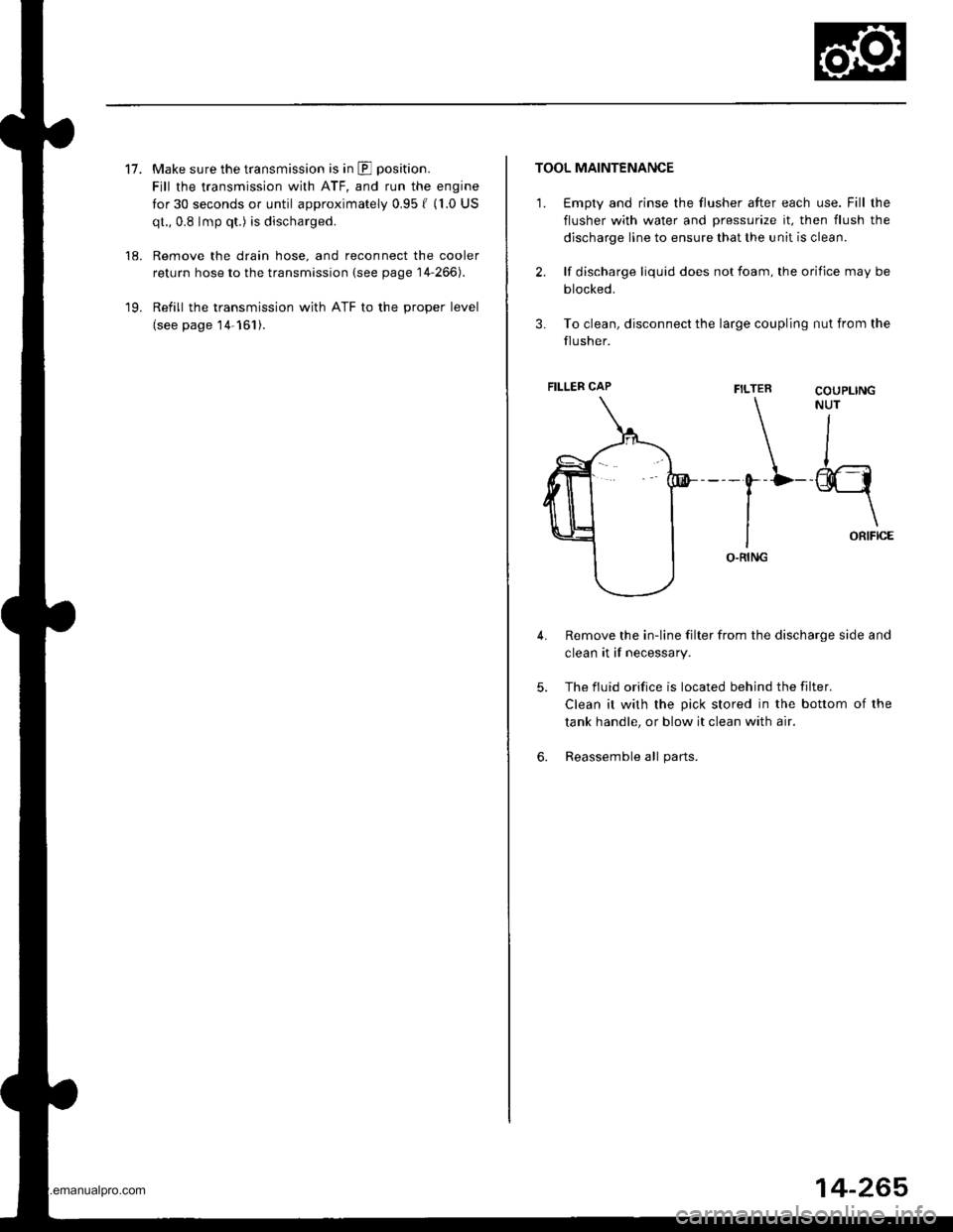
TOOL MAINTENANCE
1. €mpty and rinse the flusher after each use. Fill the
flusher with water and pressurize it, then flush the
discharge line to ensure that the unit is clean.
2. lf discharge liquid does not foam, the orifice may be
blocked.
3. To clean, disconnect the large coupling nut from the
flusher.
FILTER
\-0--D
I
IO.RING
Remove the in-line filter from the discharge side and
clean it if necessary.
The fluid orifice is located behind the filter.
Clean it with the pick stored in the bottom of the
tank handle, or blow it clean with air.
Reassemble all parts.
COUPLINGNUT
II
-@q
\ORIFICE
4.
5.
6.
FILLER CAP
14-265
www.emanualpro.com