shaft HONDA CR-V 2000 RD1-RD3 / 1.G Workshop Manual
[x] Cancel search | Manufacturer: HONDA, Model Year: 2000, Model line: CR-V, Model: HONDA CR-V 2000 RD1-RD3 / 1.GPages: 1395, PDF Size: 35.62 MB
Page 14 of 1395
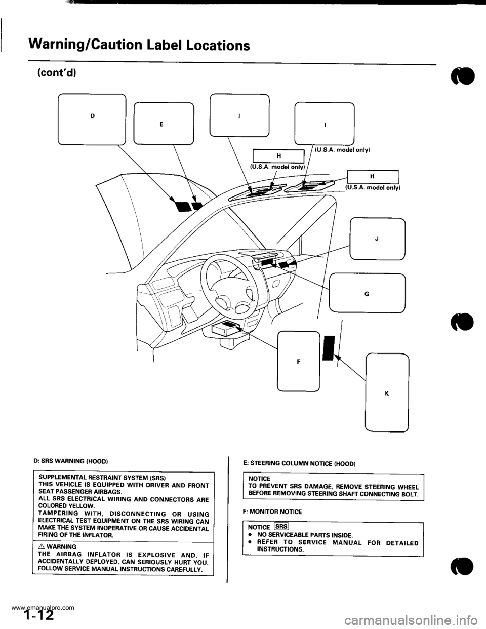
Warning/Caution Label Locations
(cont'dl
(U.S.A. modelonlyl
E: STEERING COLUMN NOTTCE tHOODI
NOTICETO PREVENT SRS DAMAGE, REMOVE STEERING WHEELBEFORE REMOVING STEERING SHAFT CONNECTING BOLT.
F: MONITOR NOTICE
NOTICE. NO SERVICEABLE PARTS tNStoE.. REFER TO SERVICE MANUAL FoR DETAILEDrNsrRucTtoNs.
{U.S.A. modol onlyl
o: SRS WARNING {HOOD}
SUPPLEMENTAL RESTRAINT SYSTEM {SRSITHIS VEHICLE IS EOUIPPED WITH DRIVER AND FRONTSEAT PASSENGER AIRBAGS,ALL SRS ELECTRICAL WIRING AND CONNECTORS ARECOLORED YELLOW.TAMPERING WITH, DISCONNECTING OR USINGELECTRICAL TEST EOUIPMENT ON THE SRS WIRING CANMAKE THE SYSTEM INOPERATIVE OR CAUSE ACCIDENTALFIRING OF THE INFLATOR.
A WARNINGTHE AIRBAG INFLATOR IS EXPLOSIVE AND. IFACCIDENTALLY DEPLOYED, CAN SEBIOUSLY HURT YOU.FOLLOW SERVICE MANUAL INSTRUCTIONS CAREFULLY.
1-12
www.emanualpro.com
Page 27 of 1395
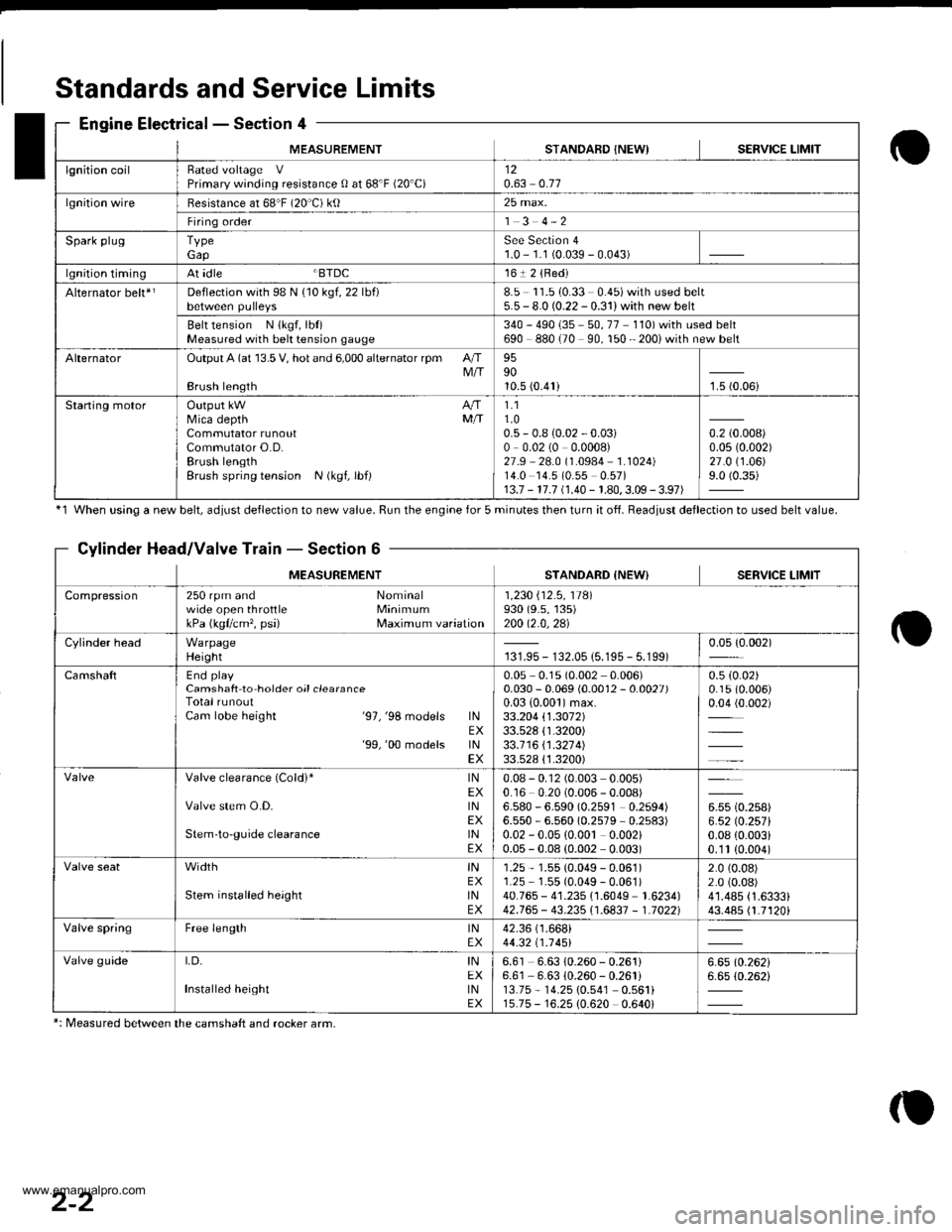
MEASUREMENTSTANDAFD INEWISERVICE LIMIT
lgnition coilRated voltage VPrimary winding resistance 0 at 68'F (20'C)120.63 0.77
lgnition wireBesistance at 68"F (20 C) ktl25 max.
Firing order1 3 4-2
Spark plugTypeGapSee Section 41.0 - 1.1 (0.039 - 0.043)
lgnition timingAt idle BTDC161 2 {Red)
Alternator belt*rDeflection with 98 N {10 kgf, 22 lbf)8.5 11.510.33 0.45)with used belt5.5 - 8.0 (0.22 - 0.31) with new belt
Belt tension N {kgf, lbt)Measured with bek tension gauge340 - 490 {35 - 50, 77 110) with used belt690 880 (70 90, 150 - 200i with new belt
AlternatorOutput A (at 13.5 V, hot and 6,000 alternator rpm AIIM/IBrush length
959010.5 (0.41)1.5 (0.06i
Staning motorOutput kW A/fMica depth MfiCommutator runoutCommutator O.D.Brush lengthBrush spring tension N (kgf, lbf)
1.11.00.5 - 0.8 {0.02 - 0.03)0,0.02 (0 0.0008)27.9 28.0 (1.0984 1.1024)14.0 14.5 (0.55 0.57)13.7 - 17.7 (1.40 - 1.80,3.09 - 3.97)
0.2 (0.008)
0.0s (0.002)
27.0 (1.06)
9.0 (0.35)
Standards and Service Limits
Engine Electrical - Section 4
'1 When using a new belt, ddiust deflection to new value. Run the engine for 5 minutes then turn it of{. Beadiust deflection to used belt value.
Cylinder Head/Valve Train - Section 6
MEASUREMENTSTANDARD {NEW} SERVICE LIMIT
Compression250 rpm and Nominalwide open throttle MinimumkPa (kgflcm'�, psi) Maximum variation
1 ,230 i'12 .5 , 11Al930 (9.s, 135)200 12.0,2al
Cylinder headWarpageHeight131.95 - 132.05 {5.195 - 5.199)0.05 {0.002)
CamshaftEnd playCamshaft to hoider oil clearanceTotal runoutCam lobe height '97,'98 models lNEX'99,'00 models lNEX
0.05 0.1s (0.002 0.006)0.030 - 0.069 (0.0012 - 0.0027)0.03 {0.001)max.33.204 \1.3072133.528 {1.3200)33.1 16 \1 .321 4)33.528 {'1.3200)
0.5 (0.02)
0.15 (0.006)
0.04 (0.002)
Valve clearance (Cold)* lNEXValve stem O.D. lNEXStem'to-guide clearance lNEX
0.08 - 0.12 (0.003 0.005)0.16 0.20 (0.006 - 0.008)6.580 - 6.590 (0.2591 0.2594)6.550 - 6.560 (0.2579 0.2s83)0.02 - 0.05 {0.00t 0.002)0.05 - 0.08 (0.002 0.003)
u* to.rutt6.52lO.257l0.08 {0.003i0.'1t (0.004)
width tNEXStem installed height lNEX
1.25 - 1.55 (0.049 - 0.061)1.25 1.55 (0.049 - 0.061)40.765 - 41.235 {1.6049 1.6234)42.765 - 43.235i'1.6837 - 1.70221
2.0 (0.08)
2.0 (0.08)
41.485 {1.6333}43.485 {1.7120i
Valve springFree length lNEX42.36 (1.668i
44.32 t1 .1 451
Valve guideI,D, INEXInstalled height tNEX
6.61 6.63 10.260 - 0.261)6.61 6.63 {0.260 - 0.261i13.75 - 14.25 10.541 0.561i15.75 - 16.25 {0.620 0.640i
6.6510.26216.65 (0.262i
*: Measured between the camshaft and rocker arm,
2-2
www.emanualpro.com
Page 28 of 1395
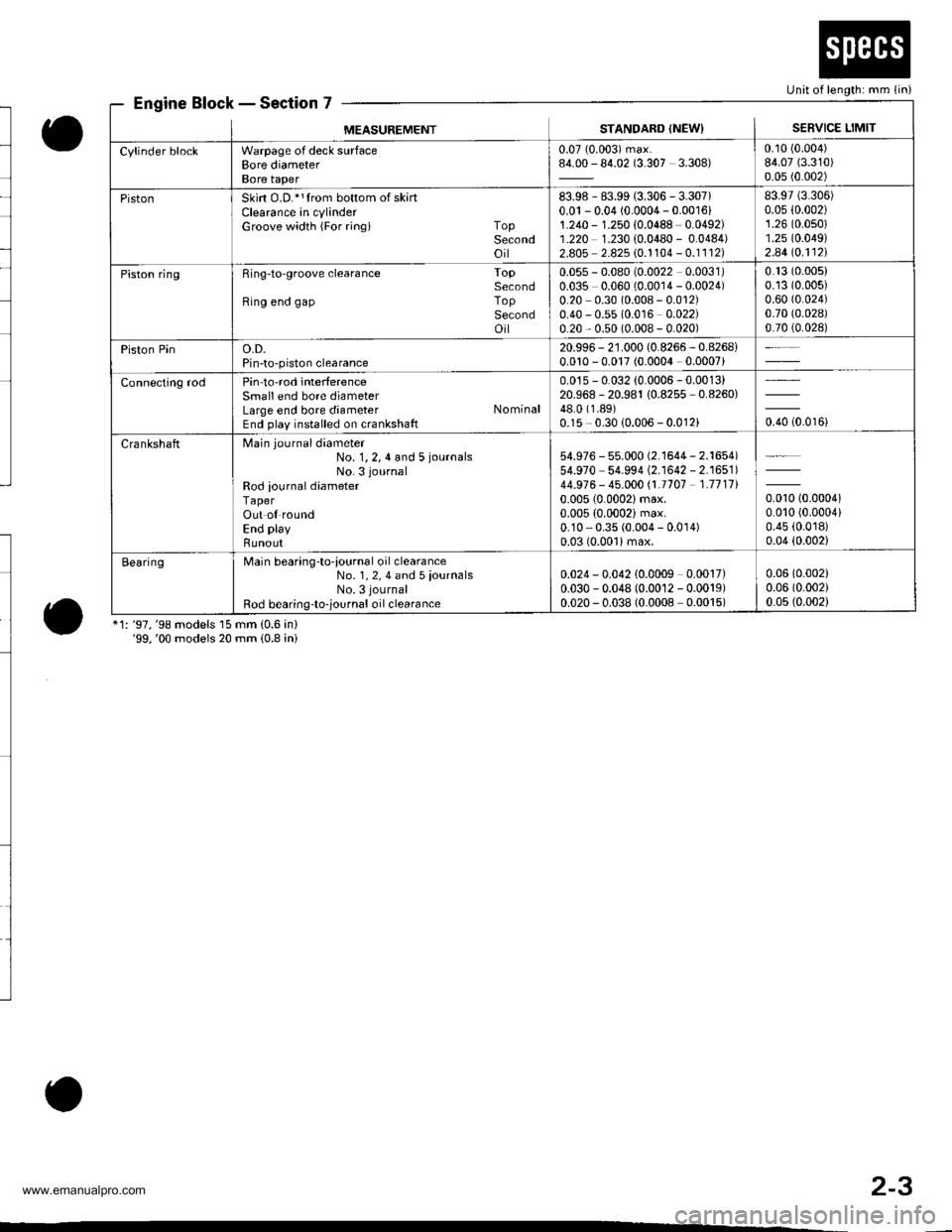
Engine Block - Section 7
o
o*1: '97,'98 models 15 mm (0.6 in)'99,'00 models 20 mm (0.8 ini
Unit of length: mm (in)
MEASUREMENTSTANDARD (NEWISERVICE LIMIT
Cylinder blockWarpage of deck surfaceBore diameterBore taper
0.07 (0.003) max.84.00 - 84.02 (3.307 3.308)0.10 (0.004)
84.07 (3.310)
0.05 (0.002)
PistonSkirt O.D.*1trom bottom of skartClearance in cylinderGroove width {For ringi TopSecondoil
83.98 - 83.99 (3.306 - 3.307)0.01 - 0.04 (0.0004 - 0.001611.240 - 1.250 {0.0488 - 0.0492)1.220 1.230 {0.0480 - 0.0484)2.805 2.825 10.1104 - 0.1112)
83.97 (3.306)
0.05 {0.002)1.26 (0.0s0)
1.25 (0.049)
2.44lo.112l
Piston ringRing-to'groove clearance ToPSecondRing end gap ToPSecondoil
0.055 - 0.080 (0.0022 0.0031)0.035 0.060 (0.0014 - 0.0024)0.20 0.30 (0.008 - 0.012)0.40 - 0.55 (0.016 0.022)0.20 - 0.50 (0.008 - 0.020)
0.13 (0.005)
0.13 (0.005)
0.60 (0.024)
0.70 (0.028)
0.70 (0.028)
Piston Pino.D.Pin-to-piston clearance
20.996 - 21.000 (0.8266 - 0.8268i0.010 - 0.017 (0.0004 - 0.0007)
Connecting rodPin-to-rod interferenceSmall end bore diameterLarge end bore diameter NominalEnd play installed on crankshaft
0.015 - 0.032 (0.0006 - 0.0013)20.968 -20.981 10.8255 -0.8260)
48.0 (1.89)
0.15 - 0.30 {0.006 - 0.012ioro to.oroi
CrankshaftMain journaldiameter
No. 1,2,4 and 5 iournalsNo. 3 journal
Rod iournal diameterTaperOut ol roundEnd play
Bunout
54.976 - 55.000 (2.'�l644 - 2.1654)54.970 54.994 (2.1642 - 2.1651)44.976 - 45.000 /.1.1707 - 1.711110.005 (0.0002)max.
0.005 (0.0002) max.0.10 - 0.35 (0.004 - 0.0 r 4)0.03 (0.001)max.
0.010 (0.00041
0.010 (0.0004)
0.45 (0.0r8)
0.04 (0.002)
BearingMain bearing-to-iournal oil clearanceNo. 1, 2, 4 and 5 iournalsNo. 3 journal
Rod bearing-to-,ournal oil clearance
0.024 - 0.042 10.0009 0.0017)0.030 - 0.048 (0.0012 - 0.0019)0.020 - 0.038 (0.0008 0.0015)
0.06 (0.002)
0.06 (0.002)
0.05 (0.002)
o
2-3
www.emanualpro.com
Page 30 of 1395
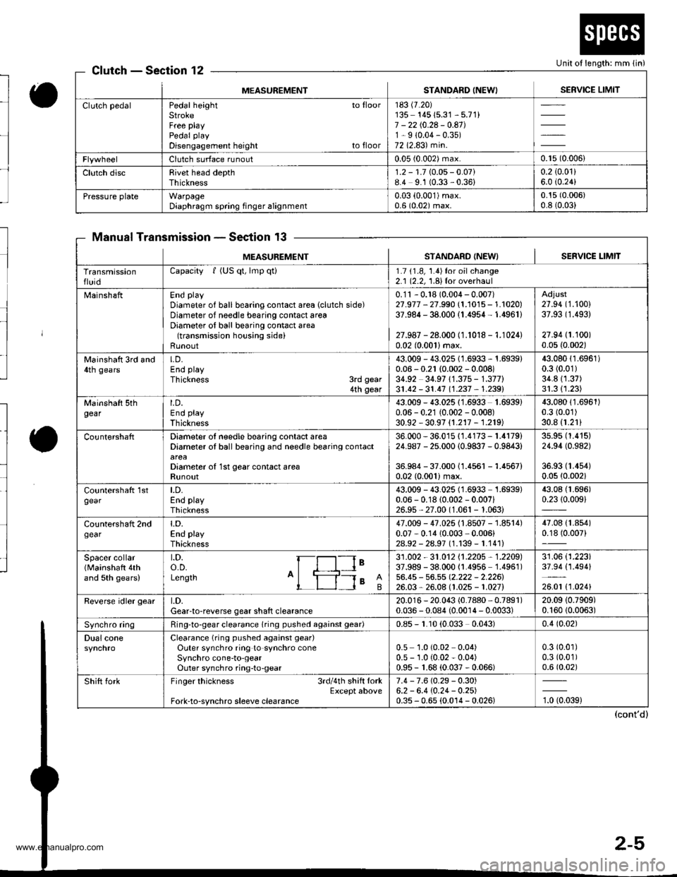
Unit of length: mm lin)ClutchSection 12
Manual TransmissionSection 13
MEASUREMENTSTANDARD INEWISERVICE LIMIT
Clutch pedalPedal height to floorStrokeFree playPedal play
Disengagement height to floor
183 (7.20)
135- 14515.31 - 5.71)7 - 2210.24 - 0.41J1-9 (0.04-0.35)
7212.83) min.
Clutch surface runout0.05 (0.002) max.0.r5 (0.006)
Clutch discRivet head depthThickness1.2 - 1.710.05- 0.07)8.4 9.1 (0.33,0.36)0.2 (0.01)
6.0 i0.24)
Pressure plateWarpageDiaphragm spring finger alignment0.03 (0.001)max.
0.6 (0.02) max.0.15 (0.006)
0.8 (0.03)
MEASUREM€NTSTANDARD INEW} I SERVICE I-IMIT
TransmissionfluidCapacity f (US qt, lmp qti1.7 11.8, 1.4)for oilchange2.1 (2.2, 1.8){or overhaul
MainshaftEnd play
Diameter of ball bearing contact area (clutch side)Diameter of needle bearing contact areaDiameter of ball bearing contact area(transmission housing side)Runout
0.'11 - 0.18 (0.004 - 0.007)27.977 - 27.990 (1.1015 - 1.1020)37.984 - 38.000 (1.4954- 1.4961)
27.987 - 28.000 (1.1018 - 1.1024)0.02 (0.0011max.
Adjust27.94 (1.100)
37.93 (1.493)
27.94 (1.100)
0.05 {0.002)
Mainshatt 3rd and4th gearsLD.End play
Thickness 3rd gear4th gear
43.009 - 43.025 1 1.6933 - 1.6939)0.06 - 0.21 (0.002 - 0.008)34.92 34.97 11.375 - 1.377)31.42 - 31.4'7 11.237 , 1.2391
43.08011.6961)0.3 (0.01)
34.811.37)31.311.23)
Mainshaft sthgearLD.End play
Thickness
43.009 - 43.02511.6933 1.6939)0.06 - 0.21 (0.002 - 0.008)30.92 - 30.97 {1.217 - 1.219)
43.08011.6961)0.3 (0.01)
30.8 (1.21)
CountershaftDiameter ol needle bearing contact areaDiameter oI ball bearing and needle bearing contact
Diameter o{ 1st gear contact areaRunout
36.000 - 36.015 {1.4173 - 1.4179)24.987 - 25.000 (0.9837 - 0.9843)
36.984 - 37.00011.4561 -1.4567)
0.02 (0.001)max.
3s.95 (1.415)
24.94 (0.982)
36.93 (1.4s4)
0.0s (0.002)
countershatt 1stgearLD.End playThickness
43.009 - 43.025 (1.6933 1.6939)0.06 - 0.18 (0.002 - 0.007i26.9s,27.00 (1.061 - 1.063)
43.08 (1.696)
0.2310.009)
Countershaft 2ndgeart.D.End playThickness
47.009 - 47.025 (1.8507 - 1.8514)0.07 - 0.14 10.003 ,0.006)
2As2 - 2a.97 l�1.139-1.1411
47.08 {1.854)0.18 (0.007)
Spacer collar(Mainshaft 4thand 5th gears)
t.D.o.D.Length A'ls I
le31 .002 - 31 .O12 11 .2205 , 1 .2205)37.989 - 38.000 (1.4956 1.4961)56.45 - 56.55 Q.222 - 2.226126.03,26.08 (1.025 - 1.027)
31.06 (1.223)
37.94 (1.494)
26.01 t1 .0241
Reverse idler geart.D.Gear-to-reverse gear shaft clearance20.01 6 - 20.043 (0.7880, 0.7891)0.036 - 0.084 (0.0014 - 0.0033)20.09 (0.7909)
0.16010.0063)
Synchro ringRing-to-gear clearance (ring pushed againsl gear)0.85 - r.10 (0.033 0.043)0.4 (0.02)
Dual coneClearance (ring pushed against gear)
Outer synchro ring to synchro coneSynchro cone-to-gearOuter synchro ring-to-gear
0.5 1.0 (0.02 0.04)0.5 - 1.0 (0.02 - 0.04)0.95 - 1.68 (0.037 - 0.066)
0.3 (0.01)
0.3 (0.01)
0.6 (0.02)
Shift forkFinger thickness 3rdl4th shift lorkExcept aboveFork-to-synchro sleeve clearance
7.4 - 7.6 (0.29 - 0.30)6.2 - 6.4 (0.24- 0.2s)0.35 - 0.65 (0.0't4 - 0.026)'t, torag)
www.emanualpro.com
Page 31 of 1395
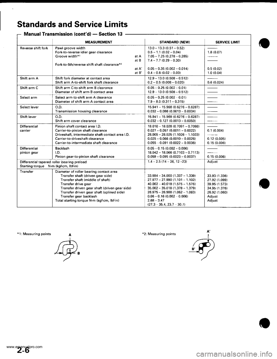
Standards and Service Limits
Manual Transmission {cont'd} - Section 13
11: fuleasuring points A
A
'Ay"
-l-...
_{-P)
A'*2: Measuring points
MEASUREMENTSTANDARO INEW) SERVICE LIMIT
Raverse shift IorkPawl groove widthFork-to-reverse idler gear clearanceGroove width*l at AatBFork-to-5th/reverse shift shaft clearance*'�
at B'
'13.0 - 13.3 (0.5'�j - 0.52)0.5 - 1.1 (0.02 - 0.04)7.O5 - 7.25 i.0.21 4 - 0.24517.4 -7.7 t0.29 0.301
0.05 - 0.35 (0.002 - 0.014)0.4,0.8 (0.02 0.03)
18 (0.07)
0.5 {0.02)1.0 (0.04)
Shift arm AShift fork diameter at contact areaShift arm A-to-shitt tork shaft clearance12.9 - 13.0 (0.508 - 0.512)0.2 - 0.5 (0.008- 0.020)0.6 {0.024i
Shift arm CShift arm C'to-shift arm B clearanceDiameter of shift arm B contact area0.05 0.25 (0.002 0.01)r2.9 - 13.0 (0.508 - 0.512)
Select armSelect arm'to-shift arm A clearanceDiameter of shift arm A contact area0.05 - 0.25 (0.002 0.01)7.9 - 8.0 (0.311 - 0.31s)
Select levero.D.Transmission housing clearance15.94r - 15.968 (0.6276 - 0.6287)0.032 - 0.086 (0.0013 - 0.0034)
Shift levero.D.Sh ift arm cover clearancer5.941 - 15.968 (0.6276 - 0.6287)0.032 - 0.127 (0.0013 - 0.0050)
DifferentialcarnerPinion shaft contact area LD.Carrier-to-pinion shaft clearanceDriveshaft, intermediate shatt contact area LD,Carrier-to-driveshaft clearanceCarrierto-interrnediate shaft clearance
18.010 18.028 (0.7091 - 0.7098)0.027 - 0.057 (0.0011 - 0.0022)28.005 - 28.025 (1.1026, 1.1033)0.025 - 0.066 (0.0010,0.0026)
0.055 - 0.091 10.0022 - 0.0036)
0.1 (0.004)
0.12 {0.005i0.15 (0.006i
Differentialpinion gearBacklasht.D.Pinion gearto-pinion shaft clearance
0.05-0.r5 {0.002 - 0.006)18.042 - 18.066 (0.7103 - 0.7113)0.059 - 0.095 10.0023 - 0.0037)oru ro.ooor
Ditferential tapered roll€r besring preloacStaning torque N.m (kgf.cm, lbl.ini
1.4 2.5i'14 26,12 -231Adjust
TransterDiameter of roller bearing contact areaTransler shaft {driven gear side}Translor shaft {middle of shaft)Transter drive gearTranslor driven gear shaft {driven gear side)Transter driven gear shaft (splined side)Trans{er gear backlashTotalstarting torque N.m (kgicm, lbiin)
33.984 - 34.000 (1.337 - 1.339)21.977 - 27.99011.101 1.102140.002 - 40.01811.575 - 1.576)35.002 - 35.01811.378 - 1.379)26.975, 26.988 (1.062 1.063)0.06 - 0.16 {0.002 0.006)2.64 3.41\21.3,35.4,23.1 30.t|
33.93 (1.336)
27 .92 (1 .O99)39.95 (1.573)
34.95 (1.376)
26.92 (1.060)
AdjustAdjust
2-6
www.emanualpro.com
Page 33 of 1395
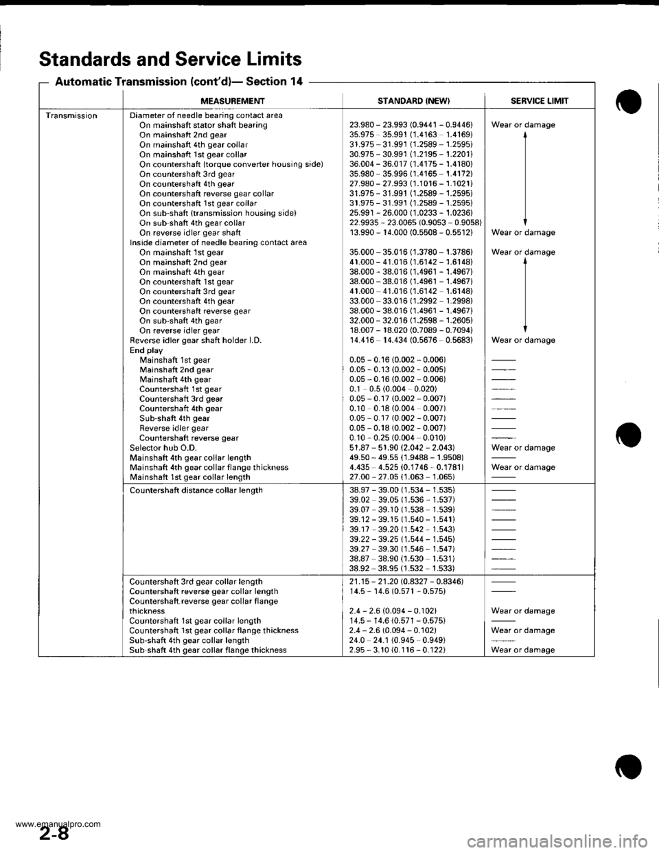
Standards and ServiceLimits
Section 14Automatic Transmission (cont'd)-
MEASUBEMENTSTANDARD {NEW}SERVICE LIMIT
TransmissionDiameter of needle bearing contact areaOn mainshaft stator shaft bearingOn mainshaft 2nd gear
On mainshaft 4th gear collarOn mainshaft 1st gear collarOn countershatt (torque converter housing side)On countershaft 3rd gear
On countershaft 4th gearOn countershaft reverse gear collarOn countershaft 1st gear collarOn sub-shaft {transmission housing sideiOn sub shaft 4th gear collarOn reverse idler gear shaftInside diameter of needle bearing contact areaOn mainshaft 1st gear
On mainshaft 2nd gearOn mainshaft 4th gear
On countershaft 1st gear
On countershaft 3rd gear
On countershaft 4th gear
On countershaft reverse gearOn sub-shaft 4th gear
On reverse idler gearfleverse idler gear shaft holder l.D.End playMainshaft 1st gearMainshaft 2nd gearMainshaft 4th gearCountershaft 1st gearCountershaft 3rd gearCountershaft 4th gear
Sub-shaft 4th gear
Reverse idler gearCountershaft reverse gear
Selector hub O.D.Mainshaft 4th gear collar lengthMainshaft 4th gear collar flange thicknessMainshaft 1st gear collar length
23.980- 23.993 (0.9441 - 0.9446)35.975 35.99'! (1.4163 1.4169)31.975 31.991 (1.2589 1.2595i30.975 - 30.991 11.2195 - 1.2201l'36.004 - 36.017 (1.4175 - 1.4180)35.980 35.996 (1.4165 1.4172)27.980 - 27.993 (1.1016 - 1.1021i31.975- 31.991 (1.2589 -'�j.2595i
31.975- 31.991 (1.2589 - 1.2595)25.991 - 26.000 (1.0233 - 1.0236)22.9935 - 23.006s (0.9053 0.9058)13.990 - r4.000 (0.5508 - 0.5512)
35.000 35.016 (1.3780 1.3786)41.000 - 41.016 (1.6142 - 1.6148)38.000 - 38.016 (1.4961 -'�1.4967)
38.000 - 38.016 (1.496'1 - 1.4967)41.000 41.016 (1.6142 1.6148)33.000 - 33.016 (1.2992 1.2998)38.000 - 38.016 (1.4961 - 1.4967)32.000 - 32.016 (1.2598 - 1.2605)18.007 - 18.020 (0.7089 - 0.7094)14.416 14.434 (0.5676 0.5683)
0.05 - 0.16 {0.002 - 0.006)0.05 - 0.13 (0.002 - 0.005)0.05,0.'16 (0.002 0.006)0.1 0.5 (0.004 0.020)0.05 0.17 {0.002 0.007)0.10 0.18 (0.004 0.007)0.0s 0.17 (0.002 - 0.007)0.05 - 0.18 (0.002 - 0.007)0.10,0.25(0.004 0.010)51.87 - 51.90 (2.042 - 2.043)49.50 - 49.55 (1.9488 - |.9508)4.435 4.525 (0.1746-0.1781)
27.00,27.05 {1.063'1.065i
Wear or damage
Wear or damage
Wear or damage
Wear or damage
il*=lo'. d"'.n"n"
Wear or damage
Countershaft distance collar length38.97 - 39.00 (1.534 - 1.535)39.02 39.05 (1.536, 1.537)39.07 39.10 (1.538 1.539)39.12 - 39.15 (1.540 - 1.541)39.17 - 39.20 (1.542 * 1.543)39.22 - 39.25 11.544 - 1.545)39.27 39.30 1'1.546 - 1.547i38.87 38.90 {1.530 1.531)38.92 38.95 (1.s32 1.533)
Countershaft 3rd gear collar lengthCountershaft reverse gear collar lengthCountershaft reverse gear collar flangethicknessCountershaft 1st gear collar lengthCountershaft lst gear collar flange thicknessSub-shaft 4th gear collar lengthSub shatt 4th gear collar flange thickness
21.15 - 21.20 rc.4327 - 0.4346)14.5, 14.6 (0.57't , 0.575)
2.4 - 2.6 (0.094 - 0.102)14.5 - 14.6 (0.571 - 0.575)2.4 - 2.6 (0.094 - 0.102)24.0 24.1 (0.945 0.949)2.95 - 3.10 (0.116 - 0.122)
Wear or damage
Wear or damage
Wear or damage
2-8
www.emanualpro.com
Page 34 of 1395
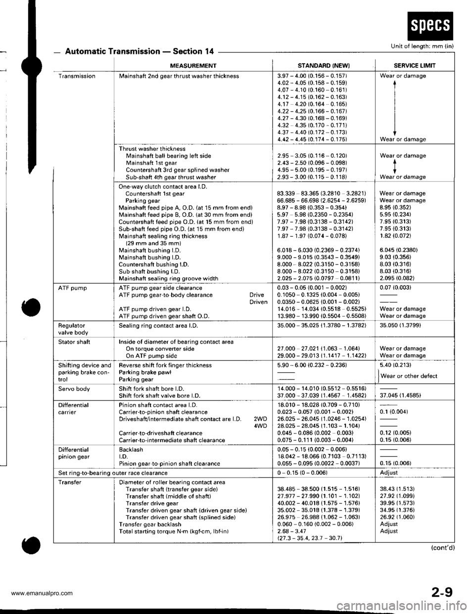
2-9
Automatic Transmission - Section 14
o
Unit of length: mm (in)
o
MEASUREMENTSTANDARD (NEWISERVICE LIMIT
TransmissionMainshaft 2nd gear thrust washer thickness3.97 - 4.00 10.156 - 0.157)4.02 - 4.05 {0.158 - 0.159)4.07 - 4.1010.160 0.161)4.12 - 4.15 (0.162 - 0.163)4.17 4.20 (0.164 0.165)4.22 - 4.25 10.166 - 0.167 )4.27 - 4.30 (0.168 - 0.169)4.32 4.35 (0.170-0.171)
4.37 - 4.40 (0.172 0.173)4.42 - 4.45 (0.174 - 0. r75)
I
I
IWear or damage
Thrust washer thicknessl'rainshaft ball bearing left sideMainshaft 1st gear
Countershaft 3rd gear splined washerSub-shaft 4th gear thrust washer
2.95 3.05 (0.116 0.120)2.43 - 2.50 (0.096 - 0.098)4.9s - 5.00 (0.195 - 0.197)2.93 - 3.00 (0.115 - 0.1181
Wear or damage
tIWear or damage
One-way clutch contact area LD.Countershaft 1st gearParking gearMainshaft feed pipe A, O.D. (at 15 mm trom end)Mainshaft feed pipe B, O.D. (at 30 mm from end)Countershaft teed pipe O.D. lat 15 mm from end)Sub-shaft feed pipe O.D. (at 15 mm from end)Mainshatt sealing ring thickness(29 mm and 35 mm)Mainshaft bushing I.D.Mainshaft bushing l.D.Countershaft bushing l.D.Sub shatt bushing LD.Mainshaft sealing ring groove width
83.339 83.365 (3.2810 3.2821)66.685 - 66.698 (2.6254 - 2.6259)8.97 - 8.98 (0.353 - 0.354)5.97 5.98 {0.2350 - 0.2354)7.97 - 7.98 (0.3138 - 0.3142)7.97 ,7.98 (0.3138 - 0.3142)1.87 - 1.97 (0.074-0.078)
6.018 - 6.030 (0.2369 - 0.2374)9.000 - 9.015 (0.3543 - 0.3549)8.000 - 8.022 (0.3150-0.3158)
8.000 - 8.022 (0.3150 0.3158)2.025 - 2.075 (0.0797 0.0811)
Wear or damageWear or damage8.95 (0.352)
5.95 (0.234)
7.95 (0.313)
7.95 {0.313)1 .42 $.O72)
5.045 (0.2380)
9.03 (0.356)
8.03 (0.316)
8.03 (0.316)
2.095 (0.082)
ATF pumpATF pump gear side clearanceATF pump gear'to body clearance DriveDrivenATF pump driven gear LD.ATF pump driven gear shaft O.D.
0.03 - 0.05 (0.001 - 0.002)0.1050 0.1325 (0.004, 0.005)0.0350 - 0.0625 10.001 - 0.002)14.016* 14.034 (0.5518 0.5525)13.980 - 13.990 {0.5504 0.5508)
0.0710.003)
Wear or damageWear or damage
Regulatorvalve bodySealing ring contact area l.D,35.000 35.025 {1.3780 - 1.3782)35.050 (1.3799)
Stator shaftInside of diameter oI bearing contact areaOn torque convener sideOn ATF pump side2't .o00 27 .021 I '1 .063 , 1 .064)29.000 - 29.01311.r417 1.1422)Wear or damageWear or damage
Shifting device andparking brake con'trol
Reverse shitt fork finger thicknessParking brake pawl
Parking gear
5.90 - 6.00 {0.232,0.236)5.40 (0.213)
lWear or other defect
Servo bodyShift fork shatt bore l.D.Shift fork shatt valve bore l.D.14.000 - 14.010 (0.55'�l2 - 0.5516)37.000 - 37.039 (1.4567 - 1.4582)37.045 (1.4585)
DifferentialcarrierPinion shaft contact area LD.Carrierto-pinion shaft clearanceDriveshafvintermediate shaft contact are l.D. 2WD4WDCarrier to driveshalt clearanceCarrier-to-intermediate shaft clearance
'18.010 - 18.028 10.709 - 0.710)0.023 - 0.057 {0.001 - 0.002}26.025 - 26.045 (1.0246 - 1.0254)28.025 - 28.045 (1.103 - 1.104)0.045 - 0.08610.002 0.003)0.075 - 0.111 10.003- 0.004)
0.r {0.004)
0.12 (0.005)
0.15 (0.006)
Differentialprnron gearBacklasht.D.Pinion gear'to-pinion shaft clearance
0.05 - 0.15 (0.002 - 0.006)18.062 - 18.066 (0.7103 - 0.7113)0.055 - 0.095 10.0022 - 0.0037)otu to.oout
Set ring-to-bearing outer race clearance0 0.15 (0 - 0.006)Adjust
TransferDiameter of roller bearing contact areaTransfer shaft (transfer gear side)Transfer shaft (middle of shaft)Transfer drive gearTransfer driven gear shaft {driven gear side)Transfer driven gear shaft {splined side)Transfer gear backlashTotalstarting torque N.m (kgf.cm, lbf.in)
38.485 38.500 (1.515 - 1.516)27 .917 - 21 .990 |.1.101 - 1.102)40.002 - 40.018 (1.575 - 1.576)35.002 35.018 (1.378 - 1.379)26.975 26.988 (1.062 -'�l.063)
0.060 0.160 (0.002 - 0.006)2.64 - 3.41127.3 - 35.4,23.1 30.71
38.43 (1.513)
27.92 (1.099)
39.95 (1.573)
34.95 (1.376)
26.92 (1.060)
AdiustAdiust
(cont'd)
www.emanualpro.com
Page 59 of 1395
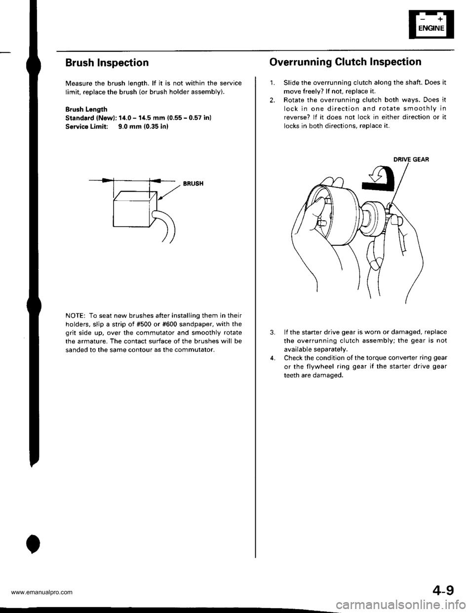
Brush Inspection
Measure the brush length. lf it is not within the service
limit, replace the brush (or brush holder assembly).
Brush Lsngth
Standard {Newl: 14.0 - I'1.5 mm (0.55 - 0.57 inl
Servico Limit: 9.0 mm (0.35 in)
NOTE: To seat new brushes after installing them in their
holders. slip a strip of #500 or #600 sandpaper, with the
grit side up, over the commutator and smoothly rotate
the armature. The contact surface of the brushes will be
sanded to the same contour as the commutator.
BRUSH
4-9
2.
1.
Overrunning Clutch Inspection
Slide the overrunning clutch along the shaft. Does it
move freely? lf not, replace it.
Rotate the overrunning clutch both ways. Does it
lock in one direction and rotate smoothly in
reverse? lf it does not lock in either direction or it
locks in both directions, reDlace it.
3.lf the starter drive gear is worn or damaged, replace
the overrunning clutch assembly; the gear is not
available separately.
Check the condition of the torque converter ring gear
or the flywheel ring gear if the starter drive gear
teeth are damaged.
www.emanualpro.com
Page 61 of 1395
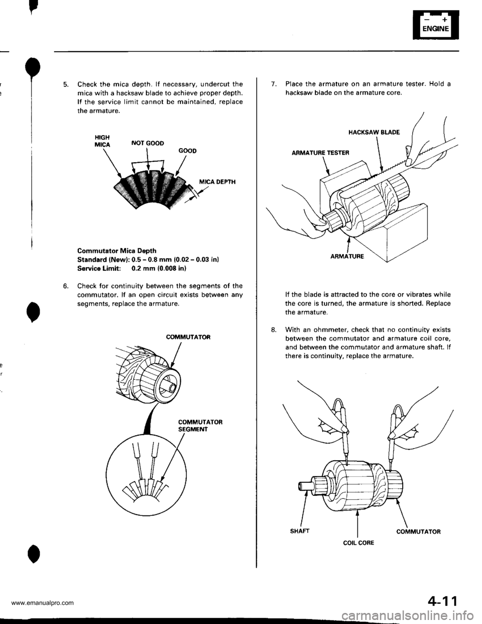
I
NOT GOOD
5. Check the mica depth. lf necessary, undercut the
mica with a hacksaw blade to achieve proper depth.
lf the service limit cannot be maintained, reDlace
the armature.
MICA DEPTI{
Commutator Mica Depth
Standard (Nsw): 0.5 - 0.8 mm 10.02 - 0.03 inl
Servico Limit: 0.2 mm (0.008 in)
Check for continuity between the segments of the
commutator. lf an open circuit exists between any
segments. replace the armature.
6.
COMMUTATOR
4-11
7. Place the armature on an armature tester. Hold a
hacksaw blade on the armature core.
lf the blade is attracted to the core or vibrates while
the core is turned. the armature is shorted. Replace
the armature.
8. With an ohmmeter, check that no continuity exists
between the commutator and armature coil core,
and between the commutator and armature shaft. lf
there is continuity. replace the armature,
cotL coRE
www.emanualpro.com
Page 66 of 1395

lgnition System
5.
lgnition Timing Inspection and Setting
2.
1.Check the idle speed, and adjust it if necessary (see
section 1 1).
Pull out the service check connector 2P (BRN and
BLK wires) from the connector holder located under
the dash on the front passenger side, then connect
the scs service connector (P/N 07PAz - 0010100) to
it.
Start the engine. Hold the engine at 3,000 rpm with
no load (A/T in N or E, Mff in neutral) until the
radiator fan comes on, then let it idle.
Connect the timing light to the No. I ignition wire,
then point the light toward the pointer on the timing
belt cover.
Check the ignition timing in no load conditions:
headlights, blower fan, rear window defogger, and
air conditioner are not operating.
lgnition Timing:
M/T: 16" 12" BTDC (RED) idling in neutral
AlTt'16" !2" BTDC (RED) idling in E or E
CRANKSHAFTPULLEY
4-16
6. lf necessary, adjust the ignition timing as follows.
Loosen the distributor mounting bolts, and turn the
distributor ignition (Dl) housing counterclockwise to
advance the timing or clockwise to retard the tim-
t no,
7.
8.
MOUNTING BOLTS24 N.m {2.4 kgf m, 17 lbtft}
Tighten the distributor mounting bolts, and recheck
the ignition timing.
Disconnect the SCS service connector from the ser-
vice check connector.
To RETARD
www.emanualpro.com