warning HONDA ELEMENT 2010 1.G User Guide
[x] Cancel search | Manufacturer: HONDA, Model Year: 2010, Model line: ELEMENT, Model: HONDA ELEMENT 2010 1.GPages: 342, PDF Size: 5.76 MB
Page 71 of 342
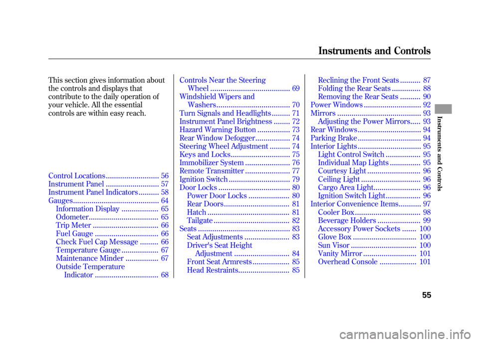
This section gives information about
the controls and displays that
contribute to the daily operation of
your vehicle. All the essential
controls are within easy reach.
Control Locations..........................56
Instrument Panel ..........................
57
Instrument Panel Indicators ..........58
Gauges ..........................................
64
Information Display ..................65
Odometer ..................................
65
Trip Meter ................................ 66
Fuel Gauge ............................... 66
Check Fuel Cap Message .........
66
Temperature Gauge ..................67
Maintenance Minder ................
67
Outside Temperature Indicator ............................... 68Controls Near the Steering
Wheel ....................................... 69
Windshield Wipers and Washers .................................... 70
Turn Signals and Headlights .........71
Instrument Panel Brightness ........
72
Hazard Warning Button ................73
Rear Window Defogger .................74
Steering Wheel Adjustment ..........
74
Keys and Locks ............................. 75
Immobilizer System ......................
76
Remote Transmitter ......................77
Ignition Switch ..............................
79
Door Locks ................................... 80
Power Door Locks ....................
80
Rear Doors ................................ 81
Hatch ........................................ 81
Tailgate .....................................
82
Seats ............................................. 83
Seat Adjustments ......................
83
Driver's Seat Height Adjustment ........................... 84
Front Seat Armrests ..................85
Head Restraints ......................... 85Reclining the Front Seats
..........
87
Folding the Rear Seats ..............
88
Removing the Rear Seats ..........90
Power Windows ............................
92
Mirrors ......................................... 93
Adjusting the Power Mirrors .....
93
Rear Windows ............................... 94
Parking Brake ............................... 94
Interior Lights ...............................
95
Light Control Switch .................95
Individual Map Lights ...............
95
Courtesy Light .......................... 96
Ceiling Light .............................
96
Cargo Area Light .......................96
Ignition Switch Light .................
96
Interior Convenience Items ...........97
Cooler Box ................................ 98
Beverage Holders .....................
99
Accessory Power Sockets .......100
Glove Box ...............................
100
Sun Visor ................................ 100
Vanity Mirror ..........................
101
Overhead Console ..................101
Instruments and Controls
55
Instruments and Controls
Page 76 of 342

Immobilizer System Indicator
This indicator comes on for a few
seconds when you turn the ignition
switch to the ON (II) position. It will
then go off if you have inserted a
properly coded ignition key. If it is
not a properly coded key, the
indicator will blink, and the engine
will not start (see page 76).
This indicator also blinks several
times when you turn the ignition
switch from the ON (II) position to
the ACCESSORY (I) or LOCK (0) position.Turn Signal and
Hazard WarningIndicators
The left or right turn signal indicator
blinks when you signal a lane change
or turn. If the indicators do not blink
or they blink rapidly, it usually
means one of the turn signal bulbs is
burned out (see page 263). Replace
the bulb as soon as possible, since
other drivers cannot see that you aresignaling.
When you press the hazard warning
button, both turn signal indicators
and all turn signals on the outside of
the vehicle flash.Daytime Running Lights Indicator
If this indicator comes on when the
ignition switch is turned to the ON
(II) position and the parking brake is
released, it means there is a problem
with a circuit. Have your vehicle
checked by your dealer.
Cruise Control Indicator
This indicator comes on when you
set the cruise control. See page 193
for information on operating the
cruise control.
Cruise Main Indicator
This indicator comes on when you
turn on the cruise control system by
pressing the CRUISE button on the
steering wheel (see page 193).
Instrument Panel Indicators
60
Table of Contents
Page 85 of 342
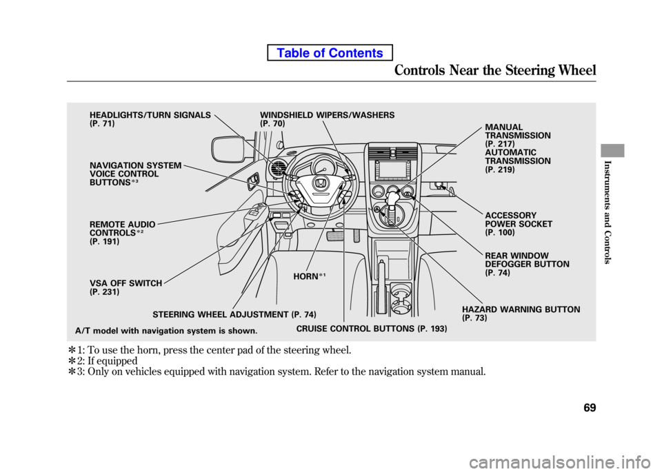
ꭧ1: To use the horn, press the center pad of the steering wheel.
ꭧ 2: If equipped
ꭧ 3: Only on vehicles equipped with navigation system. Refer to the navigation system manual.
HAZARD WARNING BUTTON
(P. 73)
CRUISE CONTROL BUTTONS (P. 193)
STEERING WHEEL ADJUSTMENT (P. 74) HORN
ꭧ
1
A/T model with navigation system is shown. VSA OFF SWITCH
(P. 231)
NAVIGATION SYSTEM
VOICE CONTROLBUTTONS
ꭧ
3
REMOTE AUDIOCONTROLSꭧ2
(P. 191)
HEADLIGHTS/TURN SIGNALS
(P. 71)
WINDSHIELD WIPERS/WASHERS
(P. 70)
REAR WINDOW
DEFOGGER BUTTON
(P. 74)
MANUAL TRANSMISSION
(P. 217) AUTOMATIC TRANSMISSION
(P. 219) ACCESSORY
POWER SOCKET
(P. 100)
Controls Near the Steering Wheel
69
Instruments and Controls
Table of Contents
Page 89 of 342
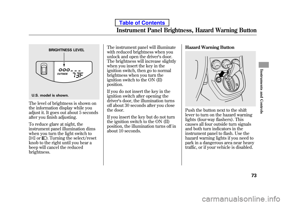
The level of brightness is shown on
the information display while you
adjust it. It goes out about 5 seconds
after you finish adjusting.
To reduce glare at night, the
instrument panel illumination dims
when you turn the light switch to
or. Turning the select/reset
knob to the right until you hear a
beep will cancel the reducedbrightness. The instrument panel will illuminate
with reduced brightness when you
unlock and open the driver's door.
The brightness will increase slightly
when you insert the key in the
ignition switch, then go to normal
brightness when you turn the
ignition switch to the ON (II)position.
If you do not insert the key in the
ignition switch after opening the
driver's door, the illumination turns
off about 30 seconds after you close
the door.
If you insert the key but do not turn
the ignition switch to the ON (II)
position, the illumination turns off in
about 10 seconds.
Hazard Warning Button
Push the button next to the shift
lever to turn on the hazard warning
lights (four-way flashers). This
causes all four outside turn signals
and both turn indicators in the
instrument panel to flash. Use the
hazard warning lights if you need to
park in a dangerous area near heavy
traffic, or if your vehicle is disabled.
BRIGHTNESS LEVEL
U.S. model is shown.
Instrument Panel Brightness, Hazard Warning Button
73
Instruments and Controls
Table of Contents
Page 99 of 342
See page 210 for information on
cargo loading. Keep the tailgate and
the hatch closed at all times while
driving to avoid damaging them, and
to prevent exhaust gas from getting
into the interior. SeeCarbon
Monoxide Hazard on page 52. Seat Adjustments
See pages 11
-13 for important safety
information and warnings about how to properly position seats and seat-backs.
Make all seat adjustments before you
start driving.
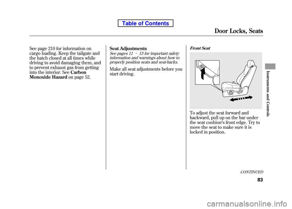
Front Seat
To adjust the seat forward and
backward, pull up on the bar under
the seat cushion's front edge. Try to
move the seat to make sure it is
locked in position.
CONTINUED
Door Locks, Seats
83
Instruments and Controls
Table of Contents
Page 101 of 342

Front Seat Armrests
On EX model
Each front seat has an armrest on the
side of the seat-back. To use it, pivot
it down.Head Restraints
See page 13 for important safety
information and a warning aboutimproperly positioning head restraints.
Your vehicle is equipped with head
restraints in all seating positions to
help protect you and your
passengers from whiplash and otherinjuries.
They are most effective when you
adjust them so the center of the back
of the occupant's head rests against
the center of the restraint.
CONTINUED
Seats
85
Instruments and Controls
Table of Contents
Page 293 of 342
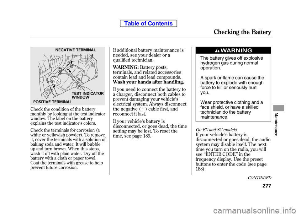
Check the condition of the battery
monthly by looking at the test indicator
window. The label on the battery
explains the test indicator's colors.
Check the terminals for corrosion (a
white or yellowish powder). To remove
it, cover the terminals with a solution of
baking soda and water. It will bubble
up and turn brown. When this stops,
wash it off with plain water. Dry off the
battery with a cloth or paper towel.
Coat the terminals with grease to help
prevent future corrosion.If additional battery maintenance is
needed, see your dealer or a
qualified technician. WARNING:
Battery posts,
terminals, and related accessories
contain lead and lead compounds.
Wash your hands after handling.
If you need to connect the battery to
a charger, disconnect both cables to
prevent damaging your vehicle's
electrical system. Always disconnect
the negative ( -) cable first, and
reconnect it last.
If your vehicle's battery is
disconnected, or goes dead, the time
setting may be lost. To reset the
time, see page 189.
The battery gives off explosive
hydrogen gas during normal operation.
A spark or flame can cause the
battery to explode with enough
force to kill or seriously hurtyou.
Wear protective clothing and a
face shield, or have a skilled
technician do the battery maintenance.
On EX and SC models
If your vehicle's battery is
disconnected or goes dead, the audio
system may disable itself. The next
time you turn on the radio, you willsee ‘‘ENTER CODE ’’in the
frequency display. Use the preset
buttons to enter the code (see page188).
NEGATIVE TERMINAL
TEST INDICATOR WINDOW
POSITIVE TERMINAL
CONTINUED
Checking the Battery
277
Maintenance
Table of Contents
Page 299 of 342
If you have a flat tire while driving,
stop in a safe place to change it.
Drive slowly along the shoulder until
you get to an exit or an area to stop
that is far away from the traffic lanes.
The vehicle can easily roll off
the jack, seriously injuring
anyone underneath.
Follow the directions for
changing a tire exactly, and
never get under the vehicle
when it is supported only by thejack.1. Park the vehicle on firm, level, and
non-slippery ground. Put the
transmission in Park (automatic)
or reverse (manual). Apply the
parking brake.
If you are towing a trailer, unhitch
the trailer.
2. Turn on the hazard warning lights, and turn the ignition switch to the
LOCK (0) position. Have all
passengers get out of the vehicle
while you change the tire.
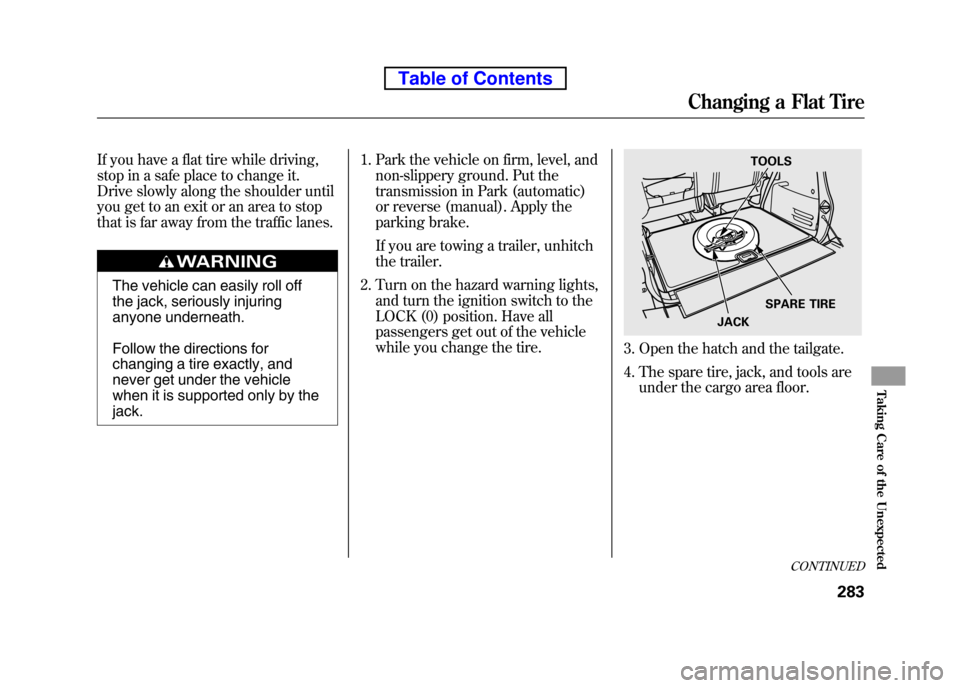
3. Open the hatch and the tailgate.
4. The spare tire, jack, and tools are
under the cargo area floor.
TOOLS
SPARE TIRE
JACK
CONTINUED
Changing a Flat Tire
283
Taking Care of the Unexpected
Table of Contents
Page 311 of 342
Low Oil Pressure Indicator
This indicator should never
come on when the engine is
running. If it starts flashing or stays
on, the oil pressure has dropped very
low or lost pressure. Serious engine
damage is possible, and you should
take immediate action.
Running the engine with low oil
pressure can cause serious mechanical
damage almost immediately. Turn off
the engine as soon as you can safely get
the vehicle stopped. 1. Safely pull off the road, and shut
off the engine. Turn on the hazard
warning lights.
2. Let the vehicle sit for a minute. Open the hood, and check the oil
level (see page 201). An engine
very low on oil can lose pressure
during cornering and other drivingmaneuvers.
3. If necessary, add oil to bring the level back to the full mark on the
dipstick (see page 251).
4. Start the engine, and watch the oil pressure indicator. If it does not go
out within 10 seconds, turn off the
engine. There is a mechanical
problem that needs to be repaired
before you can continue driving(see Emergency Towing on page
303). Charging System Indicator
If the charging system
indicator comes on brightly
when the engine is running, the
battery is not being charged.
Immediately turn off all electrical
accessories. Try not to use other
electrically operated controls such as
the power windows. Keep the engine
running; starting the engine will
discharge the battery rapidly.
Go to a service station or garage
where you can get technicalassistance.
Low Oil Pressure Indicator, Charging System Indicator
295
Taking Care of the Unexpected
Table of Contents
Page 327 of 342

The tires on your vehicle meet all
U.S. Federal Safety Requirements.
All tires are also graded for
treadwear, traction, and temperature
performance according to
Department of Transportation (DOT)
standards. The following explains
these gradings.
Uniform Tire Quality Grading
Quality grades can be found where
applicable on the tire sidewall
between tread shoulder and
maximum section width. For example:Treadwear 200
Traction AA
Temperature A
All passenger car tires must conform
to Federal Safety Requirements in
addition to these grades. Treadwear
The treadwear grade is a
comparative rating based on the wear
rate of the tire when tested under
controlled conditions on a specified
government test course. For
example, a tire graded 150 would
wear one and one-half (1 1/2) times
as well on the government course as
a tire graded 100. The relative
performance of tires depends upon
the actual conditions of their use,
however, and may depart
significantly from the norm due to
variations in driving habits, service
practices and differences in road
characteristics and climate.
Traction
The traction grades, from highest to
lowest, are AA, A, B, and C. Those
grades represent the tire's ability to
stop on wet pavement as measured
under controlled conditions on
specified government test surfaces of
asphalt and concrete. A tire marked
C may have poor tractionperformance.
Warning: The traction grade
assigned to this tire is based on
straight-ahead braking traction tests,
and does not include acceleration,
cornering, hydroplaning, or peak
traction characteristics.
DOT Tire Quality Grading (U.S. Vehicles)
311
Technical Information
Table of Contents