fuse box HONDA FIT 2020 Owner's Manual (in English)
[x] Cancel search | Manufacturer: HONDA, Model Year: 2020, Model line: FIT, Model: HONDA FIT 2020Pages: 599, PDF Size: 41.91 MB
Page 8 of 599
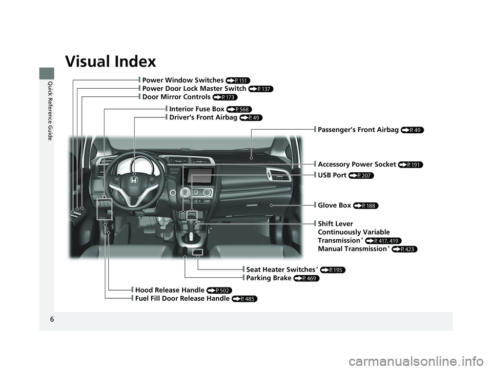
Visual Index
6
Quick Reference Guide
❙Glove Box (P188)
❙Shift Lever
Continuously Variable
Transmission
* (P417, 419)
Manual Transmission* (P423)
❙Seat Heater Switches* (P195)
❙Parking Brake (P469)
❙Hood Release Handle (P502)
❙Fuel Fill Door Release Handle (P485)
❙Accessory Power Socket (P191)
❙Passenger’s Front Airbag (P49)
❙USB Port (P207)
❙Interior Fuse Box (P568)
❙Driver’s Front Airbag (P49)
❙Power Window Switches (P151)
❙Power Door Lock Master Switch (P137)
❙Door Mirror Controls (P173)
20 FIT-31T5A6500.book 6 ページ 2019年9月26日 木曜日 午後4時41分
Page 409 of 599
Continued407
uuTowing a Trailer uTowing Your Vehicle
Driving
■Extended Towing
If you tow more than eight hours in one day, you should repeat the “When Your
Vehicle is Towed Behind a Motorhome” procedure from the previous page at least
every eight hours.
You also need to perform the following procedure to prevent the battery from
running down.
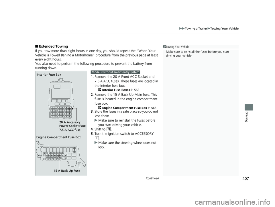
1.Remove the 20 A Front ACC Socket and
7.5 A ACC fuses. These fuses are located in
the interior fuse box.
2 Interior Fuse Boxes P. 568
2.Remove the 15 A Back Up Main fuse. This
fuse is located in the engine compartment
fuse box.
2 Engine Compartment Fuse Box P. 5663.Store the fuses in a safe place so you do not
lose them.
u Make sure to reinstall the fuses before
you start driving your vehicle.
4. Shift to
(N.
5. Turn the ignition switch to ACCESSORY
(q.
u Make sure the steering wheel does not
lock.
1Towing Your Vehicle
Make sure to reinstall the fuses before you start
driving your vehicle.
Engine Compartment Fuse Box
15 A Back Up Fuse
Interior Fuse Box
20 A Accessory
Power Socket Fuse
7.5 A ACC fuseModels without smart entry system
20 FIT-31T5A6500.book 407 ページ 2019年9月26日 木曜日 午後4時41分
Page 410 of 599
408
uuTowing a Trailer uTowing Your Vehicle
Driving
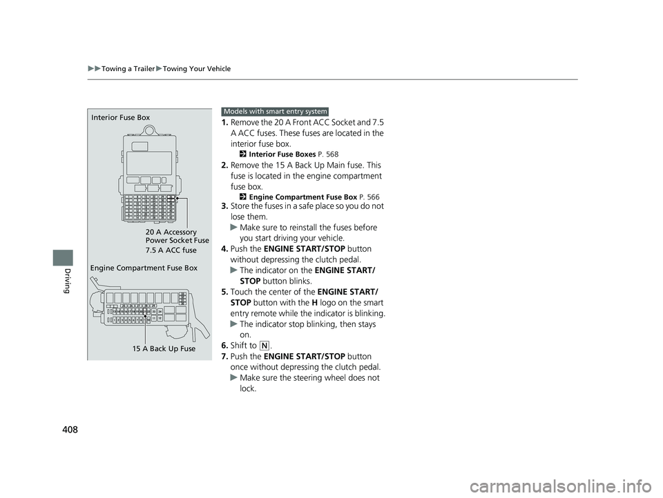
1. Remove the 20 A Front ACC Socket and 7.5
A ACC fuses. These fuses are located in the
interior fuse box.
2 Interior Fuse Boxes P. 568
2.Remove the 15 A Back Up Main fuse. This
fuse is located in th e engine compartment
fuse box.
2 Engine Compartment Fuse Box P. 5663.Store the fuses in a safe place so you do not
lose them.
u Make sure to reinstall the fuses before
you start driving your vehicle.
4. Push the ENGINE START/STOP button
without depressing the clutch pedal.
u The indicator on the ENGINE START/
STOP button blinks.
5. Touch the center of the ENGINE START/
STOP button with the H logo on the smart
entry remote while the indicator is blinking.
u The indicator stop blinking, then stays
on.
6. Shift to
(N.
7. Push the ENGINE START/STOP button
once without depressing the clutch pedal.
u Make sure the steering wheel does not
lock.
Engine Compartment Fuse Box
15 A Back Up Fuse
Interior Fuse Box
20 A Accessory
Power Socket Fuse
7.5 A ACC fuseModels with smart entry system
20 FIT-31T5A6500.book 408 ページ 2019年9月26日 木曜日 午後4時41分
Page 559 of 599
557Continued
Handling the Unexpected
Jump Starting
Turn off the power to electric devices, such as audio and lights. Turn off the engine,
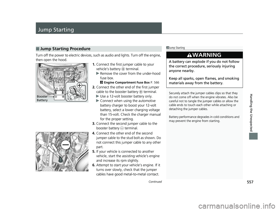
then open the hood. 1.Connect the first jumper cable to your
vehicle’s battery + terminal.
u Remove the cover from the under-hood
fuse box.
2 Engine Compartment Fuse Box P. 566
2.Connect the other end of the first jumper
cable to the booster battery + terminal.
u Use a 12-volt booster battery only.
u Connect when using the automotive
battery charger to boost your 12-volt
battery, select a lower charging voltage
than 15-volt. Check the charger manual
for the proper setting.
3. Connect the second jumper cable to the
booster battery - terminal.
4. Connect the other end of the second
jumper cable to the stud bolt as shown. Do
not connect this jumper cable to any other
part.
5. If your vehicle is connected to another
vehicle, start the assisting vehicle’s engine
and increase its rpm slightly.
6. Attempt to start your ve hicle’s engine. If it
turns over slowly, check that the jumper
cables have good metal-to-metal contact.
■Jump Starting Procedure1 Jump Starting
Securely attach the jumper cables clips so that they
do not come off when the e ngine vibrates. Also be
careful not to tangle the ju mper cables or allow the
cable ends to touch each other while attaching or
detaching the jumper cables.
Battery performance degrades in cold conditions and
may prevent the engi ne from starting.
3WARNING
A battery can explode if you do not follow
the correct procedure, seriously injuring
anyone nearby.
Keep all sparks, open flames, and smoking
materials away from the battery.
Booster
Battery
20 FIT-31T5A6500.book 557 ページ 2019年9月26日 木曜日 午後4時41分
Page 568 of 599
566
Handling the Unexpected
Fuses
Fuse Locations
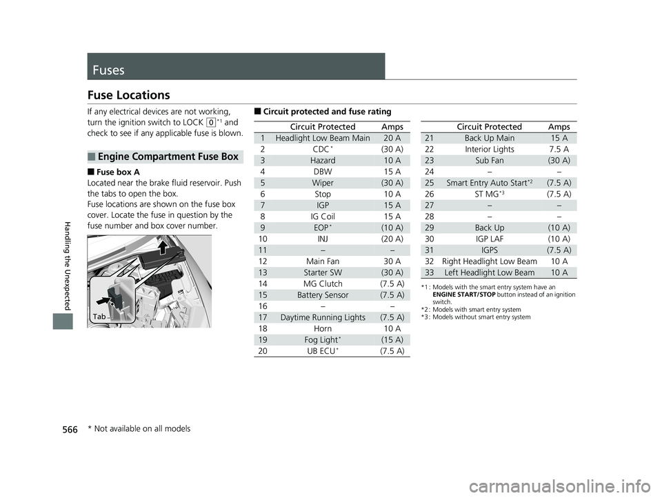
If any electrical devices are not working,
turn the ignition switch to LOCK
(0*1 and
check to see if any appl icable fuse is blown.
■Fuse box A
Located near the brake fluid reservoir. Push
the tabs to open the box.
Fuse locations are shown on the fuse box
cover. Locate the fuse in question by the
fuse number and box cover number.
■Engine Compartment Fuse Box
Tab
■Circuit protected and fuse rating
Circuit ProtectedAmps
1Headlight Low Beam Main20 A
2CDC*(30 A)
3Hazard10 A
4DBW15 A
5Wiper(30 A)
6Stop10 A
7IGP15 A
8IG Coil15 A
9EOP*(10 A)
10INJ(20 A)
11––
12Main Fan30 A
13Starter SW(30 A)
14MG Clutch(7.5 A)
15Battery Sensor(7.5 A)
16––
17Daytime Running Lights(7.5 A)
18Horn10 A
19Fog Light*(15 A)
20UB ECU*(7.5 A)
*1 : Models with the smart entry system have an ENGINE START/STOP button instead of an ignition
switch.
*2 : Models with smart entry system
*3 : Models without smart entry system
Circuit ProtectedAmps
21Back Up Main15 A
22Interior Lights7.5 A
23Sub Fan(30 A)
24––
25Smart Entry Auto Start*2(7.5 A)
26ST MG*3(7.5 A)
27––
28––
29Back Up(10 A)
30IGP LAF(10 A)
31IGPS(7.5 A)
32Right Headlight Low Beam10 A
33Left Headlight Low Beam10 A
* Not available on all models
20 FIT-31T5A6500.book 566 ページ 2019年9月26日 木曜日 午後4時41分
Page 569 of 599
567
uuFuses uFuse Locations
Continued
Handling the Unexpected
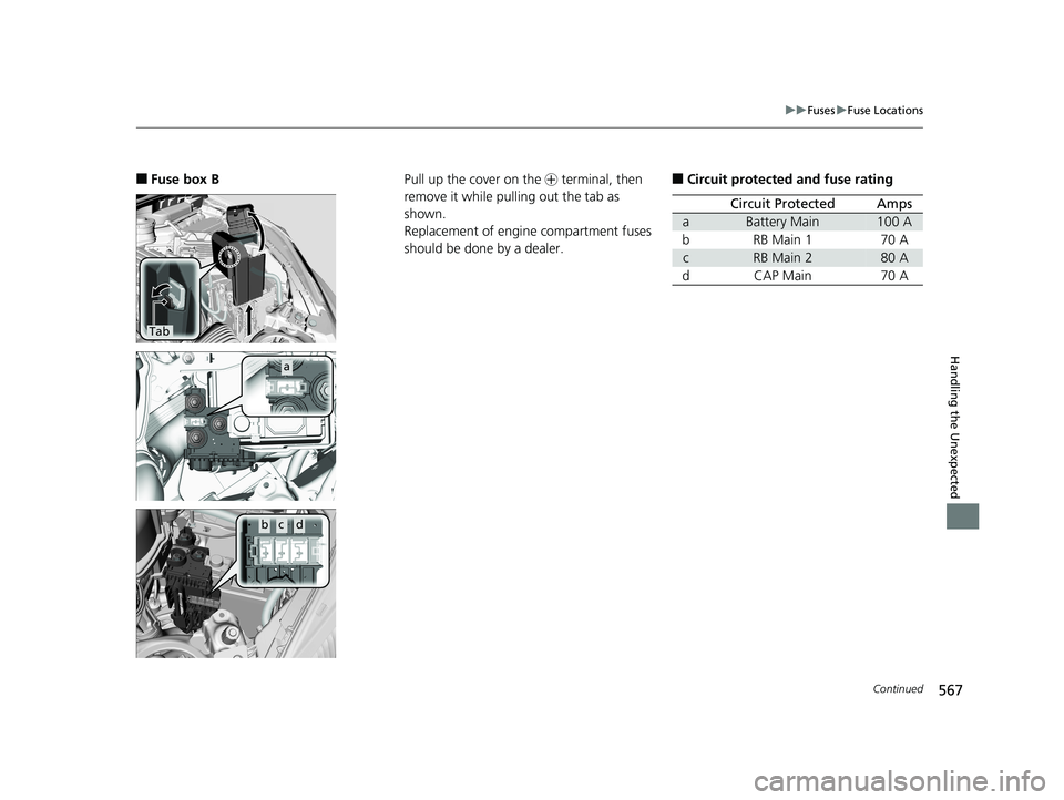
■Fuse box B
Tab
a
bcd
Pull up the cover on the + terminal, then
remove it while pulling out the tab as
shown.
Replacement of engine compartment fuses
should be done by a dealer.■Circuit protected and fuse rating
Circuit ProtectedAmps
aBattery Main100 A
bRB Main 170 A
cRB Main 280 A
dCAP Main70 A
20 FIT-31T5A6500.book 567 ページ 2019年9月26日 木曜日 午後4時41分
Page 570 of 599
568
uuFuses uFuse Locations
Handling the Unexpected
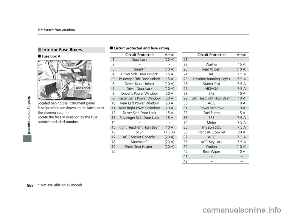
■Fuse box A
Located behind the instrument panel.
Fuse locations are shown on the label under
the steering column.
Locate the fuse in question by the fuse
number and label number.
■Interior Fuse Boxes
Fuse Label
■Circuit protected and fuse rating
Circuit ProtectedAmps
1Door Lock(20 A)
2––
3Smart*(10 A)
4Driver Side Door Unlock15 A
5Passenger Side Door Unlock15 A
6Driver Door Unlock(10 A)
7Driver Door Lock(10 A)
8Driver’s Power Window20 A
9Passenger’s Power Window20 A
10Rear Left Power Window20 A
11Rear Right Power Window20 A
12Driver Side Door Lock15 A
13Passenger Side Door Lock15 A
14––
15Right Headlight High Beam10 A
16STS*(7.5 A)
17ACC Socket Console*(20 A)
18Moonroof*(20 A)
19Front Seat Heater*(20 A)
20––
Circuit ProtectedAmps
21––
22Washer15 A
23Rear Wiper*(10 A)
24A/C7.5 A
25Daytime Running Lights7.5 A
26Starter Cut7.5 A
27ABS/VSA7.5 A
28SRS10 A
29Left Headlight High Beam10 A
30ACG10 A
31Power Window10 A
32Fuel Pump15 A
33SRS7.5 A
34Meter7.5 A
35Mission SOL7.5 A
36Front ACC Socket20 A
37ACC7.5 A
38ACC Key Lock7.5 A
39Option(10 A)
40Rear Wiper10 A
41−−
42−−
* Not available on all models
20 FIT-31T5A6500.book 568 ページ 2019年9月26日 木曜日 午後4時41分
Page 571 of 599
569
uuFuses uFuse Locations
Handling the Unexpected
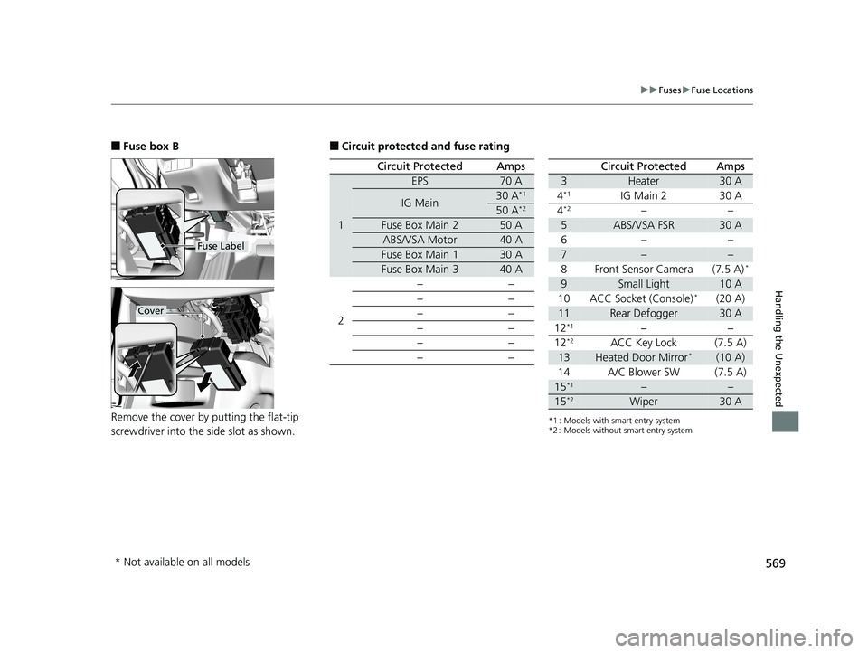
■Fuse box B
Remove the cover by putting the flat-tip
screwdriver into the side slot as shown.
Fuse Label
Cover
■Circuit protected and fuse rating
Circuit ProtectedAmps
1
EPS70 A
IG Main30 A*1
50 A*2
Fuse Box Main 250 A
ABS/VSA Motor40 A
Fuse Box Main 130 A
Fuse Box Main 340 A
2 ––
––
––
––
––
––
*1 : Models with smart entry system
*2 : Models without smart entry system
Circuit ProtectedAmps
3Heater30 A
4*1IG Main 230 A
4*2––
5ABS/VSA FSR30 A
6– –
7––
8 Front Sensor Camera (7.5 A)*
9Small Light10 A
10 ACC Socket (Console)*(20 A)
11Rear Defogger30 A
12*1−−
12*2ACC Key Lock (7.5 A)
13Heated Door Mirror*(10 A)
14 A/C Blower SW (7.5 A)
15*1––
15*2Wiper30 A
* Not available on all models
20 FIT-31T5A6500.book 569 ページ 2019年9月26日 木曜日 午後4時41分
Page 572 of 599
570
uuFuses uInspecting and Changing Fuses
Handling the Unexpected
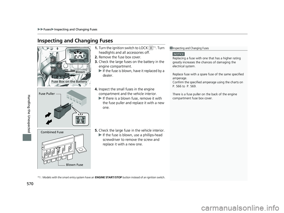
Inspecting and Changing Fuses
1. Turn the ignition switch to LOCK (0*1. Turn
headlights and all accessories off.
2. Remove the fuse box cover.
3. Check the large fuses on the battery in the
engine compartment.
u If the fuse is blown, have it replaced by a
dealer.
4. Inspect the small fuses in the engine
compartment and the vehicle interior.
u If there is a blown fuse, remove it with
the fuse puller and replace it with a new
one.
5. Check the large fuse in the vehicle interior.
u If the fuse is blown, use a phillips-head
screwdriver to remo ve the screw and
replace it with a new one.
*1 : Models with the smart entry system have an ENGINE START/STOP button instead of an ignition switch.
1Inspecting and Changing Fuses
NOTICE
Replacing a fuse with on e that has a higher rating
greatly increases the chances of damaging the
electrical system.
Replace fuse with a spare fuse of the same specified
amperage.
Confirm the specified amperage using the charts on
P. 566 to P. 569.
There is a fuse puller on the back of the engine
compartment fuse box cover.
Fuse Box on the Battery
Blown
Fuse Puller
Combined Fuse
Blown Fuse
20 FIT-31T5A6500.book 570 ページ 2019年9月26日 木曜日 午後4時41分