Page 98 HONDA INTEGRA 1994 4.G Workshop Manual
[x] Cancel search | Manufacturer: HONDA, Model Year: 1994, Model line: INTEGRA, Model: HONDA INTEGRA 1994 4.GPages: 1413, PDF Size: 37.94 MB
Page 3 of 1413
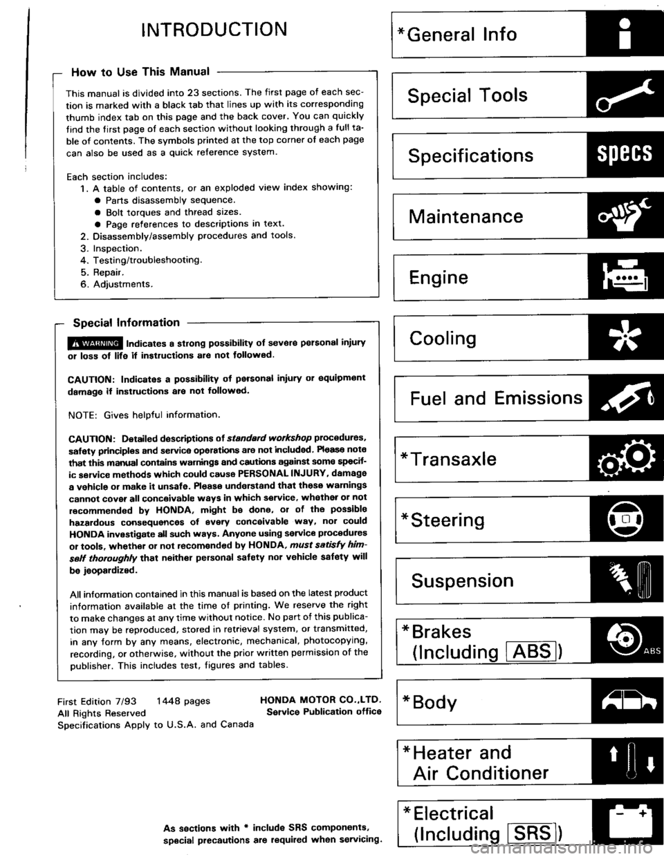
INTRODUCTION
How to Use This Manual
This manual is divided into 23 sections. The first page of each sec-
tion is marked with a black tab that lines up with its corresponding
thumb index tab on this page and the back cover. You can quickly
tind the tirst page of each section without looking through a full ta-
ble of contents. The svmbols printed at the top corner of each page
can also be used as a quick reference system.
Each section includes:
1. A table of contents. or an exploded view index showing:
a Parts disassemblv sequence.
a Bolt toroues and thread sizes.
a Page references to descriptions in text.
2. Disassemblv/assembly procedures and tools.
3. InsDection.
4. Testing/troubleshooting.
5. Repair.
6. Adiustments.
Special Information
@ lnai""tes a strong possibility of sevor€ pelsonal iniury
01 loss of life it instructions al€ not tollowed.
CAUTION: Indicates a possibility ot personal inlury or oquipmont
damage if instructions ale not followed.
NOTE: Gives helpful information.
CAUTfON: Detaifed doscriptions ot standad workshop procedures,
salety principlos and servica opelations are not included Pleaso note
that this manual conlains warnings and cautions against somo spocif-
ic sgrvice methods which could cause PERSONAL INJURY, damage
a vehicle or make it unsafe. Pleaso understand that those warnings
cannot cover all conceivablc waYs in which service, whethea or not
recommended bv HONDA, might be done, or of the possibla
hazardous consequences of svery conceivable way, nor could
HONDA investigate all such ways. Anyone using seryice plocedures
or toofa, whethor 01 not recomonded by HONDA, ,nust sttisfY him-
sett thoroughly that neither personal saf€ty nor v€hicle safety will
be jaopaldized.
All information contained in this manual is based on the latest product
information available at the time of printing. We reserve the right
to make changes at any time without notice. No part of this publica-
tion mav be reproduced, stored in retrieval system, or transmitted,
in any Jorm by any means, electronic, mechanical, photocopying,
recording, or otherwise, without the prior written permission of the
publisher. This includes test. figures and tables.
Specificationstrtl:{lt'
Maintenance4Pi
Engine
H
I-""
Fuel and Emissions Za
*Transaxle
*Steeringr-\
lDl\.t/
* Brakes
(lncludins !TEg)o
*Electrical J--*
(lncludins ISBE)
First Edition 7/93 1448 pages
All Rights Reserved
Specifications Apply to U.S.A. and Canada
HONDA MOTOR CO.,LTD,
Service Publication ottice
As sections with r includ€ SRS components.
special precautions are lequiled when servicing.
Page 4 of 1413
,,
SUPPLEMENTAL RESTRAINT SYSTEM (SRS}
The Integra SRS includes a driver's airbag, located in the steering wheel hub. ln addition, all mod€ls excepi tna
Rs model for canada have a front passenger's airbsg located in the dashboard above the glove box, InformaUon
necessary to safely service the SRS is included in this servica Manual. ltems marked with an sstorisk (r) on thr
contents page include, or are located near, SRS components. Servicing. disassembling or roplacing thea6 ltems
will require special precautions and tools, and should thoreiore be done by an authorhed Acura dealer.
' To avoid rondering ths sRS inoporativo, which could lard to porronll Injury or darth In thc cvant ot. r.yr.
trontal collision, all sRs sorvico work must be pcrformcd by !n ruthorizcd Acu.! daerrr,
' lmpTopor 3orvica proceduroa, including inco.roct r.movd r d Installation of tha SRS, could Lld to pc[onc Inlu-
ry caussd by unintsntional activation ot tho airbags.
' All sRs oloctrical wiring harnoa$! aro coverod with yallow In3ulatlon, Rcbtcd componcnts arc bcrtad In tha
stoering Golumn, front console, dsrhboa.d, and darhboard lowor plnol, lnd in thc d$hbolrd abovc tha gaov!
bor. Do not uas oloctdcal te$ oquipmont on thaaa citcuhs.
NoTE: The original radio has a coded thett protection circuit. Be sure to get the customer's code numb6r b€lore* disconnecting the battery.
- removing the No. 32 (7.S A) fuse Jrom the undsr-hood fuse/relay box.
- removing the radio.
After service, reconnect power to the radio and turn it on. When the word ,,CODE,, is displayed, enter the cus_
tomer's 5-digit code to restore radio oDerauon.
Page 14 of 1413
and Support Points
Jack
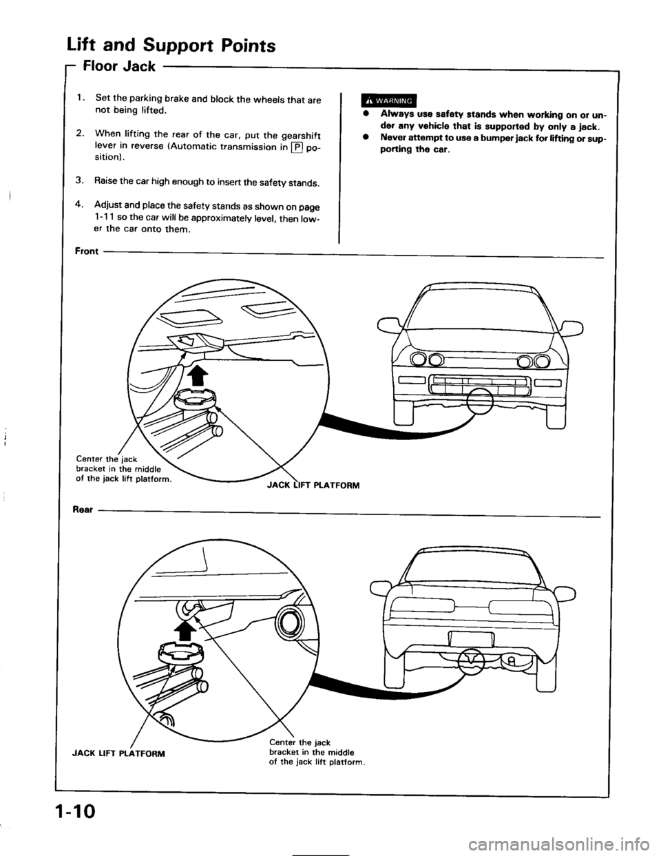
Set the parking brake and block the wheels that are
not being lifted.
2.When lifting the rearwhen tritrng the rear of the car, put the gearshift
lever in reverse (Automatic transmission in @ po-
of
sition).
Raise the car high enough to insen the safety stands.
Adjust and place the safety stands as shown on page
1-1 1 so the car will be approximately level, then low-
er the car onto them.
Front
oor
ft
FI
Li
4.
1.
a
Always uss satety stands when working oo 01 un-
der any vehicle that is supponed by only a jack.
Naver attompt to use a bumpor iack fo. lifting or sup-
porting tho car,
3.
Center the
bracket in
ot the jack
the middle
lift platform.
jsck
JACK LIFT PLATFORM
Rear
JACK LIFT PLATFORM
Center the jack
bracket in the middle
of the jack Iift platform.
1-10
Page 19 of 1413
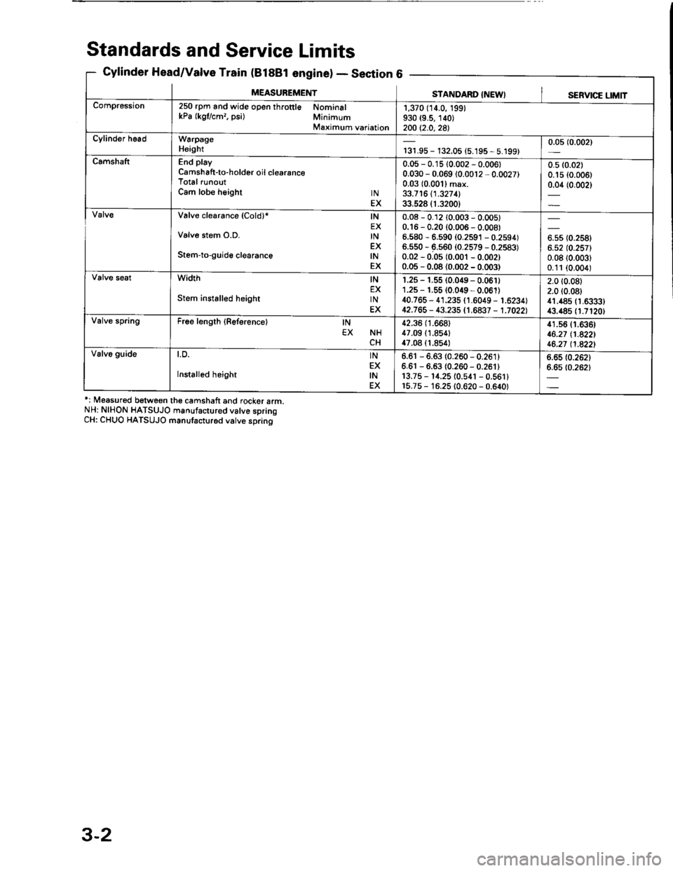
Standards and Service Limits
Cylinder Head/Valve Train (B188t enginelSecti6
*: Measured between the camshaft and rocker arm.
NH: NIHON HATSUJO manufactur€d valve spring
CH: CHUO HATSUJO manufacturod valve sDrino
- Declron
MEASUREMENTSTANDARD {NEWI '
SERVICE LIMIT
Compression250 rpm and wide open th.ottl€ Nominal
kPa (kgflcm?, psi) Minimum
Maximum variation
1,370 (14.0, 199)
930 (9.5, 140)
200 t2.0,2a)
Cylinder h.adW6rpage
Heightr31.95- 132.05 (5.195 - 5.199)
0.05 (0.002)
CamshaftEnd play
Camshaft-to-holder oil clearance
Total runout
Cam lobe height tN
EX
0.05 - 0.15 (0.002 - 0.0061
0.030 - 0.069 10.0012 - 0.0027)
0.03 (0.001) max.
33.7 16 11 .327 1l
33.528 (1.3200)
0.5 (0.02)
0.1s {0.006)
0.04 (0.002)
Valve clearance (Cold)* lN
EX
Valve stem O.D. tN
EX
Stem-to-guide clearance lN
EX
0.08 - 0.12 {0.003 - 0.005)
0.'r 6 - 0.20 (0.006 - 0.008)
6.580 - 6.590 (0.2591 - 0.2594)
6.550 - 6.s60 (0.2579 - 0.2583)
0.02 - 0.0s (0.001 - 0.002)
0.05 - 0.08 (0.002 - 0.003)
6.s5 (0.258)
6.52 (0.257)
0.0810.003)
0.11 (0.004)
width tN
EX
Stem instslled height tN
EX
r.25 - 1.55 (0.049 - 0.061)
1.25 - 1.55 {0.049 - 0.061)
40.765 - 41.235 (1.6049 - 1.6234)
12.763 - 43.235 t1,6a37 - 1.7022)
2.0 t0.08)
2.0 (0.08)
41.485 (1.6333)
43.485 (1.7120)
Valve springFree length {Reference} lN
EX NH
CH
42.36 (1.668)
47.09 {1.854}
47.08 (1.854)
41.s6 {1.636)
46.27 tl.A22l
46.21 l1.a22l
Valv6 guideLu. lN
EX
Installed height lN
6.61 - 6.63 (0.260 - 0.261)
6.61 - 6.6s (0.260- 0.261)
13.75 - 14.25 {0.541 - 0.561}
r5.75 - 16.25 10.620 - 0.640)
6.65 (0.262)
6.6510.2621
3-2
Page 20 of 1413
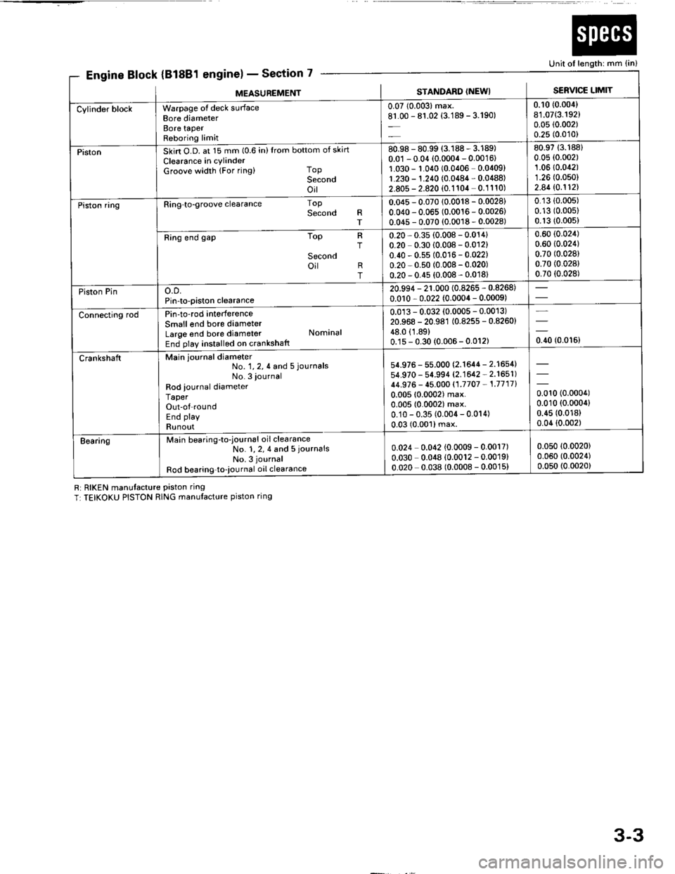
k (81881
Ri RIKEN manutacture Piston ring
T:TEIKOKU PISTON RING manufacture piston ring
7scti
Unit of length: mm {in}
Engine Block {Bl6E1 englnel - sectlon
MEASUNEMENTSTANDARD (NEWI SERVICE LIMIT
bottom of skirt
Top
Second
oil--
top
Second
'....=-
lop
Ring to-groove clearance
Ring end gap
o.D.
Pin-to-piston clearance
Pin-to-rod interference
Smallend bore diameter
Large end bore diameter
End play installed on crankshatt
Main journal diameter
Warpage ot deck sLrrface
Bore diameter
Bore taPer
Reboring limit
Skirt O.D. at 15 mm (0.6 in)Irom
Clearance in cylinder
Groove width (For ring)
R
T
;
T
No. 1, 2, 4 and 5 journals
No. 3 iournal
Rod iournal diameter
Taper
Out-of round
End play
Runout
Main bearing-to-iournal oil clearance
No. 1, 2, 4 and 5 journals
No. 3 journal
Rod bearing to-iournal oil clearance
Second
oit R
T
Nominal
0.0710.003)max.
81.00 - 81.02 {3.189 - 3.190)
0.10 (0.004)
81.07(3.192)
0.05 (0.002)
0.25 (0.010)
Cylinder block
80.98 - 80.99 (3.188 - 3.189)
0.01 - 0.04 (0.0004 - 0.0016)
1.030 - r.010 (0.0406 0.0409)
1.230 - 1.210 (0.0484 - 0.0488)
2.805 - 2.820 (0.1104 0.1110)
80.9713.188)
0.05 (0.002)
1.0610.042)
1.26 (0.050)
2.8410.112\
Piston
0.045 - 0.070 {0.0018 - 0.0028}
0.040 - 0.065 (0.0016 - 0.0026)
0.045 - 0.070 (0.0018 - 0.0028)
0.13 {0.00s)
0.13 (0.00s)
0.13 (0.005)
0.60 {0.024)
0.60 10.024)
0.70 (0.028)
0.70 (0.028)
0.70 (0.028)
Piston ring
0.20 - 0.35 (0.008 - 0.014)
0.20 0.30 (0.008 - 0.012)
0.40 - 0.5s (0.0 r6 - 0.022)
0.20 - 0.s0 (0.008 - 0.020)
0.20 - 0.45 (0.008 - 0.0181
20.994 - 21.000 (0.8265 - 0.8268)
0.0r0 - 0.022 (0.0004 - 0.0009)
rrston rln
0.013 - 0.032 (0.0005 - 0.0013)
20.968 - 20.981 (0.825s - 0.8260)
48.0 (1.89)
0.1s - 0.30 (0.006 - 0.012)
Connecting rod
54.976 - 55.000 (2.1644 - 2.1654)
54.970 - 54.994 (2.1642 - 2.1651)
44.S76 - 45.000 {1.7707 - 1.7717}
0.00510.0002) max.
0.005 (0.0002) max.
0.10 - 0.35 (0.004 - 0.014)
0.03 (0.001) max.
0.010 (0.0004)
0.010 (0.0004)
0.45 (0.018)
0.04 {0.002)
Crankshaft
0.024 0.042 {0.0009 - 0.0017)
0.030 0.048 {0.0012 - 0.0019}
0.020 0.038 (0.0008 - 0.0015)
0.05010.0020)
0.060 (0.0024)
0.050 (0.0020)
Bearing
3-3
Page 21 of 1413
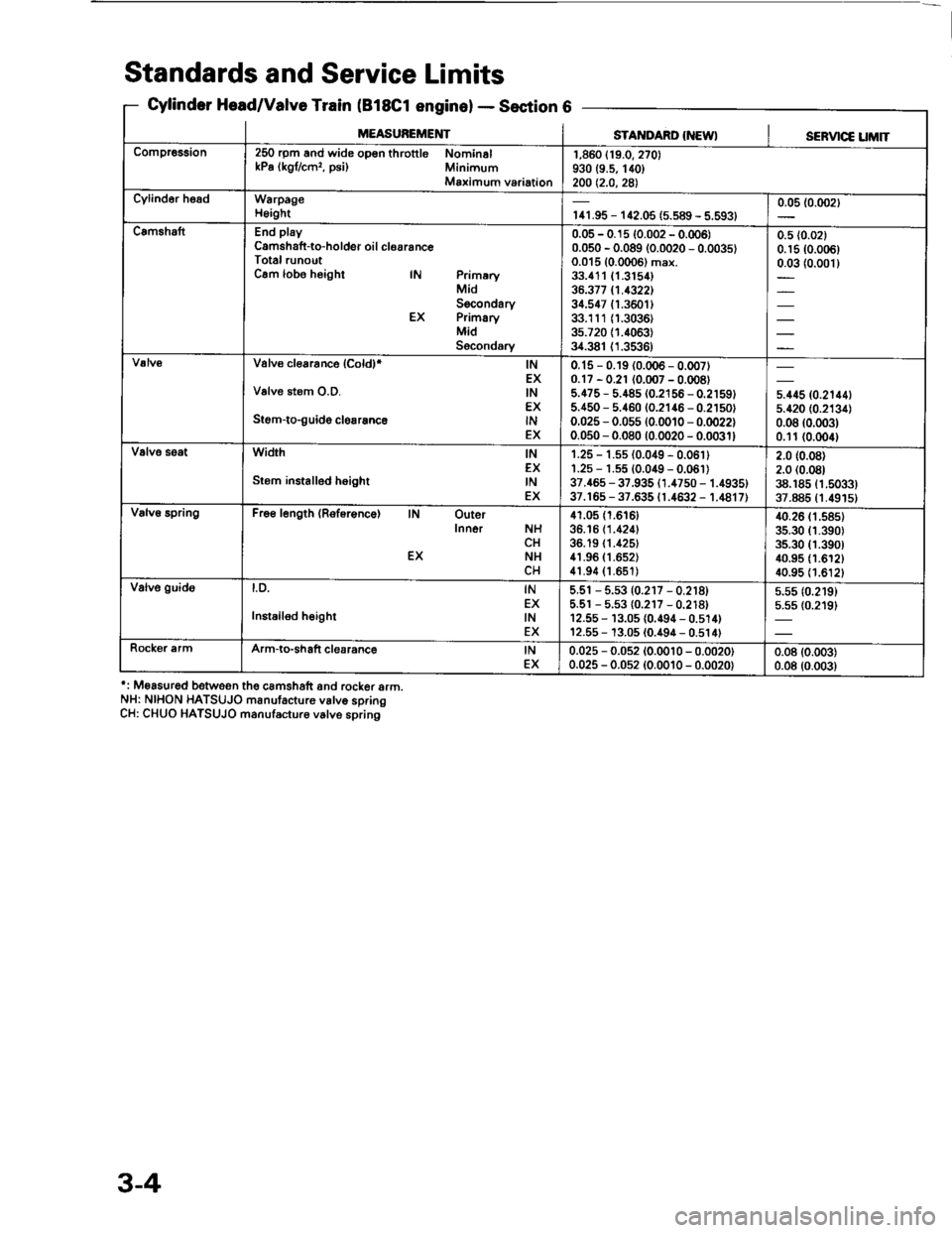
Standards and Service Limits
Cylander Head/Valve Train (B18Cl enginelSection 6
': M€asured betwoon the camshatt and rcc(er srm.
NH: NIHON HATSUJO manufacture v6lve spring
CH: CHUO HATSUJO manufscturo v6lve spring
MEASUBEMENTSTA]TDARD INEWISERV|C€ UM|T
Compr€6sion250 rpm and wide op€n throttle Nomin6l
kPa lkgl/cmr, psi) Minimum
Maximum variation
1,860 (19.0, 270)
930 (9.s, 140)
200 t2.o,2a)
Cylind6r hoadWarpage
H6ight'r41.95 - 1C2.05 (5.s89 - 5.593)
0.05 {0.002)
C.mshsftEnd play
Camshaft-to-holdsr oil clearance
Total runout
Cam lobo height lN Primery
Mid
Socondary
EX Primary
Mid
Secondary
0.05 - 0.1s (0.002 - 0.006)
0.050 - 0.089 (0.0020 - 0.0035)
0.015 (0.0006) max.
33.411{1.3154)
36.377 tl.13221
34.547 (1.3601)
33.1110.3036)
35.72011.4063)
34.381 {1.3536)
0.5 (0.02)
0.15 {0.006)
0.03 (0.001)
Valvo clorrance lcoldl* lN
EX
Valve stem O.D. lN
EX
Stom-to-guid6 clerrsnco lN
EX
0.15 - 0.19 {0.006 - 0.007}
0.17 - 0.21 (0.007 - 0.008)
5.475 - 5.48s (0.2156 - 0.21591
5.450 - 5.460 (0.2146 - 0.21s0'
0.025 - 0.055 {0.00'10 - 0.0022}
0.050 - 0.080 (0.0020 - 0.0031)
5.11510.21441
s.420 {0.2134)
0.08 10.003)
0.11{0.(x)4)
Valvo seatWidth tN
EX
Sr6m installed h€ight lN
EX
1.25 - 't.5s (0.049 - 0.06't)'1.25 - 1.s5 {0.049 - 0.061)
37.465 - 37.935 ('1.4750 - 1.4935)
37.16s - 37.635 t1.4632 - 1.4817)
2.0 (0.08)
2.0 (0.08)
38.185 (1.5033)
37.885 (1.491s)
Valv€ BpringFre6length (Roferenca) lN Outer
Inner NH
CH
EX NH
CH
41.05 (r.6161
36.'16 {1.4241
36.19 t1.425)
41.96 (1.652)
41.94 {1.651)
40.26 (1.585)
35.30 (1.390)
35.30 (1.390)
40.95 (1.612)
40.95 (1.612)
Valve guidol.D. tN
EX
Instslled hoight lN
EX
5.51 - 5.53 (0.217 - 0.218)
5.5r - 5.53 {0.2r7 - 0.218)
12.55 - r3.0s (0.494 - 0.514)
12.55 - 13.05 (0.494 - 0.s14t
5.55 (0.219)
5.5s {0.219}
Rock€r ermArm-to-shaft clearance lN
EX
0.025 - 0.0s2 {0.0010 - 0.0020)
0.025 - 0.0s2 (0.0010 - 0.0020)
0.08 (0.003)
0.08 (0.003)
3-4
Page 22 of 1413
![HONDA INTEGRA 1994 4.G Workshop Manual EBIk (818C1Section 7
Unit of length: mm (in)
ngrne ]ocK (ltluur englnel -
MEASUREMENTSTANDARD (NEWI SERVIC€ LIMIT
Cyiinder blockwarpage of deck surlace
Bore diameter
Bore taPer
Reboring limit
0.05 HONDA INTEGRA 1994 4.G Workshop Manual EBIk (818C1Section 7
Unit of length: mm (in)
ngrne ]ocK (ltluur englnel -
MEASUREMENTSTANDARD (NEWI SERVIC€ LIMIT
Cyiinder blockwarpage of deck surlace
Bore diameter
Bore taPer
Reboring limit
0.05](/img/13/6067/w960_6067-21.png)
EBIk (818C1Section 7
Unit of length: mm (in)
ngrne ]'ocK (ltluur englnel -
MEASUREMENTSTANDARD (NEWI SERVIC€ LIMIT
Cyiinder blockwarpage of deck surlace
Bore diameter
Bore taPer
Reboring limit
0.05 (0.002) max.
81.00 - 81.02 {3.189 - 3.190)
0.08 (0.003)
81.0713.192)
0.05 (0.002)
0.25 (0.010)
PistonSkin O.D. ar 15 mm (0.6 in) {rom bottom ot skirt
Clearance in cylinder
Groove width (For ring) ToP
Socond
oil
80.98 - 80.99 13.188 - 3.189)
0.0r - 0.04 {0.0004 - 0.0016}
1.030 - 1.0,r0 {0.0406 - 0.0409)
1.230 - 1.240 (0.0484 - 0.0488)
2.805 - 2.820 (0.1104 - 0.11101
80.97 (3.188)
0.05 (0.002)
1.060 (0.0417)
1.260 (0.0496)
2.840 (0.1118)
Piston ringRing-to-pistongrooveclearance Top
Second
0.045 - 0.070 {0.0018 - 0.0028}
0.010 - 0.065 (0.0016 - 0.0026)
0.13 (0.005)
0.13 (0.005)
Ring end gap I oP
Socond
oil
0.20 - 0.35 {0.008 - 0.014)
0.40 - 0,55 (0.016 - 0.022)
0.20 - 0.s0 {0.008 - 0.020}
0.60 (0.024)
0.70 (0.028)
0.7010.0281
rrston rtno.D.
Pin-to-piston clearance
20.994 - 21.000 (0.8265 - 0.8268)
0.010 - 0.022 {0.0004 - 0.0009)
0.017 - 0.035 (0.0007 - 0.0014)
20.964 - 20.997 (0.8254 - 0.8267)
€.0 (1.89)
0.15 - 0.30 (0.006 - 0.012)
Connecting rodPin to-rod int€rference
Small end bore diameter
Large end bore diameter Nominal
End play installed on crankshaft
crankshatt
No. 1,2,4 and 5 iournals
No. 3 journal
Rod iournal diameter
Taper
Out'ol round
End play
Runout
Msin journal diameter
54.976 - 55.000 (2.1644 - 2.16541
54.974 - 54.998 (2.'�|643 - 2.1553)
44.976 - 45.000 {1.7707 -'�I.7717)
0.005 {0.0002} max.
0.004 {0.0002) max.
0.10 - 0.35 {0.00{ - 0.014)
0.020 (0.0008) max.
-t-oou
lo.ooort
EearingMain bsaring-to-journal oil clearance
No. 1, 2, 4 and 5 journals
No 3 journal
Rod bearing-to-journal oil clearanc€
0.024 - 0.042 (0.0009 - 0.0017)
0.030 - 0.048 (0.0012 - 0.0019)
0.032 - 0.050 (0.0013 - 0.0020)
0.050 (0.0020)
0.060 {0.0024)
0.060 (0.0024)
3-5
Page 24 of 1413
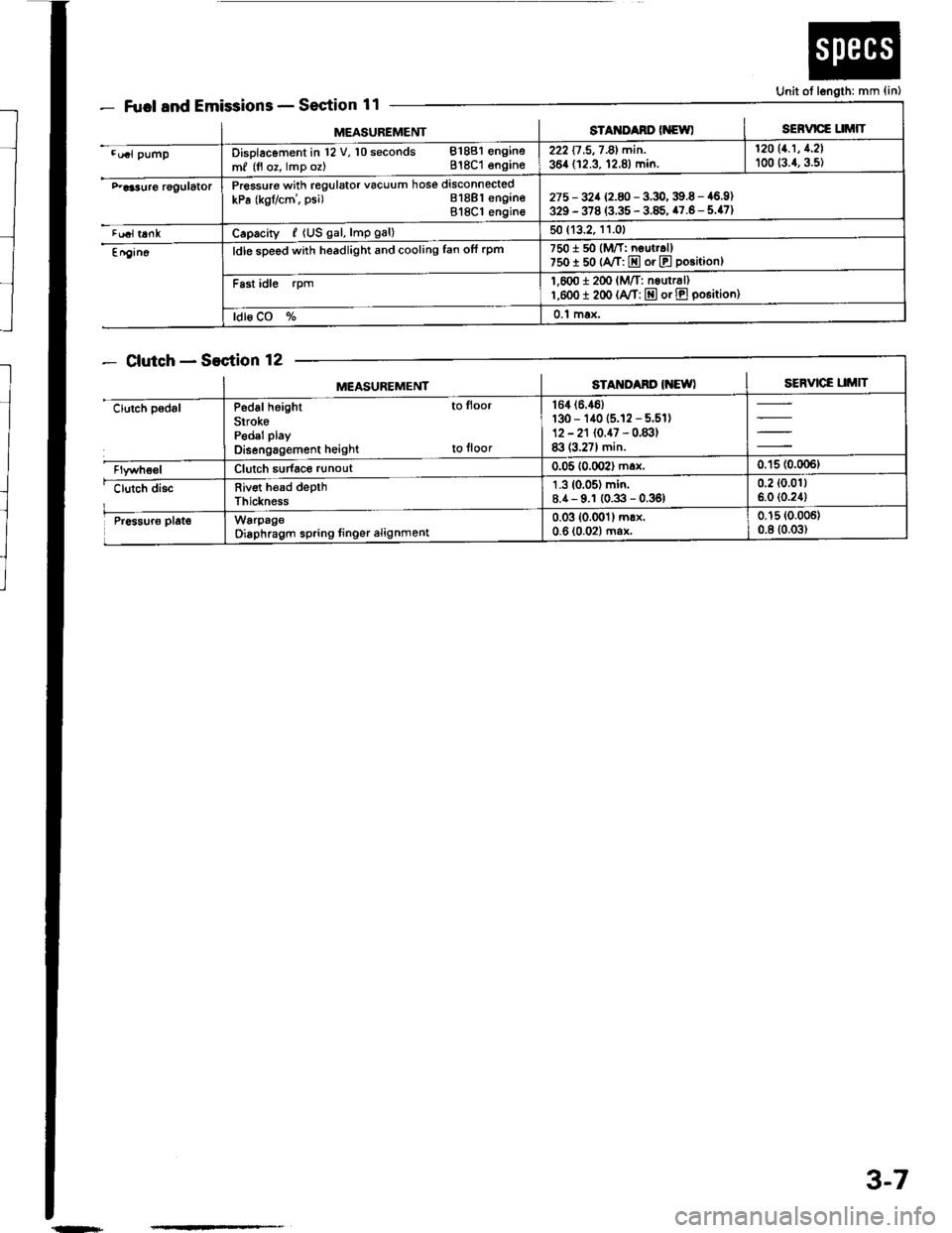
Fuel and EmissionsSection 11
ClutchSection 12
Unit ot length: mm {in)
MEASUREMENTsTAt{ItAno (NewlSERVICE UMIT
.u.l pumpDisolacoment in l2 V, 10 seconds 81881 engine
m, (fl oz, lmp oz) 818C1 engins222 17 .5,7 -81 min. | 12011.1' 1'21
364 (12.3, 12.8) min. I too (:.1, g.st
F aa3uro rggulatorPressure with regulator vacuum hose disconnected
kPa (kgflcm', psi) Bl8Bl engineBl8Cl engin€275 - 32a 12.8 -3.9,39.6 - 46.9)329 - 378 (3.35 - 3.85, 47.6- 5.47)
tualt6nkCaprcity, {US gal, lmp gal)50 (13.2, 11.01
En9in6ldle sDeed with headlight and cooling fan ofi rpm7501 50 (M/T: neut..ll750I 50 {A/T: E or E position}
Fast idle rpm1,600 i 2(x' lM/T: nsurr6l)l,eoo I 200 (A/T: E or E po6itioo)
ldl6 CO %0.1 max.
MEASUREMENTSTAM'Ad' IiEWISERVICE UMIT
clutch padslP6d6l height to lloor
SirokePedal play
Disengagement height to floor
164 (6.46)
130 - 140 (5.12 - 5.51)12 - 21 (0.47 - 0.83)83 (3.27) min.
Clutch sudace runout0.05 10.002) max,0.'15 (0.006t
clutch discRiv€t h€ad depthThickness
1.3 (0.05) min.8.4- 9.1 (0.3 - 0.36)0.2 (0.011
6.0 (0.24)
Pr6sur6 plat€WarpageOiaphragm spring linger alignment0.03 (0.001) mrx.0-6 (0.02) ma*0.15 (0.006)
0.8 (0.03)
{n+
3-7
Page 52 of 1413
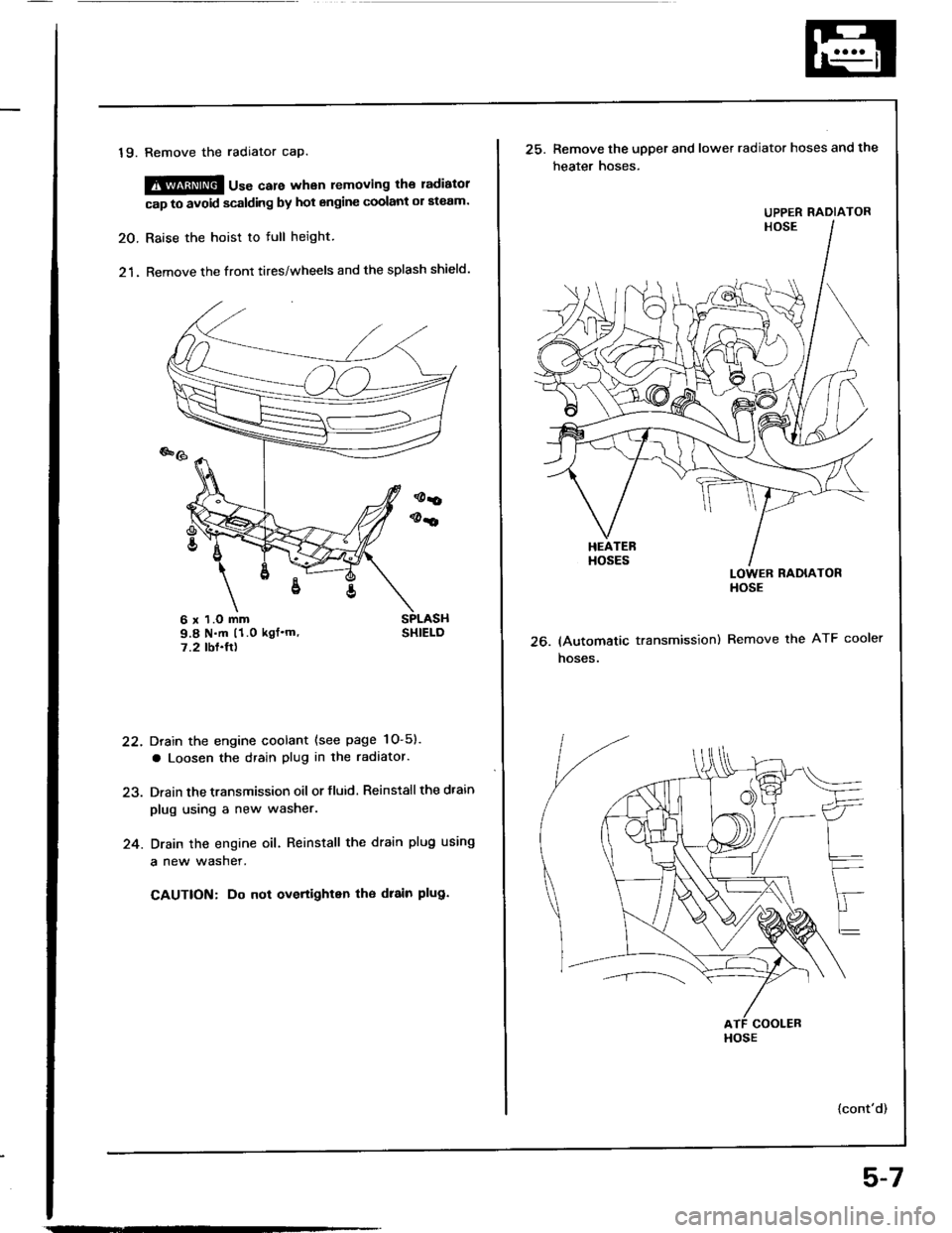
19. Remove the radiator cap.
@@ u"" care whan removing the ladiatol
cap to avoid scalding by hot engine coolant ol ateam.
20. Raise the hoist to full height.
21. Remove the front tires/wheels and the splash shield.
Drain the engine coolant (see page 1O-5).
a Loosen the drain plug in the radaator.
Drain the transmission oil or fluid. Reinstall the dtain
plug using a new washer.
Drain the engine oil. Reinstall the drain plug using
a new wasner.
CAUTION: Do not overtighten tho drain plug.
22.
24.
6 x 1.O mm9.8 N.m (1.0 kgf'm'7.2 tbf.ft)26.
25. Remove the upper and lower radiator hoses and the
heater hoses.
LOWER RADIATORHOSE
(Automatic transmission) Remove the ATF cooler
hoses.
{cont'd)
UPPER RADIATOR
HOSE
5-7
Page 53 of 1413
*l
Engine Removal/lnstallation
(cont'dl
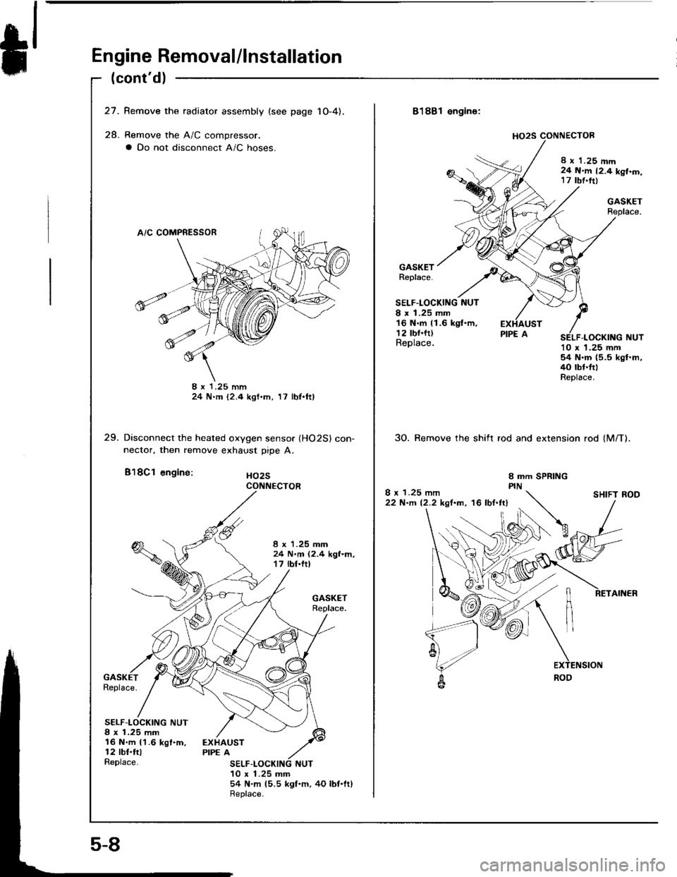
27. Remove the radiator assembly {see page 1O-4),
28. Remove the A/C compressor.
a Do not disconnect A/C hoses.
8 x '1.25 mm24 N.m t2.4 kgf.m, 17 lbl.ftl
29. Disconnect the heated oxygen sensor (HO2Sl con-nector, then remove exhaust pipe A.
B'l8Cl engine: Ho2s
I x 1.25 mm24 N.m (2.4 kgf.m,17 rbt.ftt
Replace.
SELF-LOCKING NUT8 x 1.25 mm16 N.m 11.6 kgf.m,12 tbl.ftlReplace.
EXHAUSTPIPE A
SELF10 x 1.25 mm54 N.m (5.5 ksf.m.4O lbf'ltlReplace.
CONNECTOR
5-8
8188l engine:
8 x 1.25 mm24 N.m 12.4 kgf.m,17 tbt.trl
GASKETReplace.
GASKETReplace.
SELF.LOCKING NUTI x 1.25 mm16 N.m (1.6 kgt.m,12 tbf.ft)Replace.10 x 1.25 mm54 N.m (5.5 kgl.m,40 tbt.ttlReplace.
30. Remove the shift rod and extension rod {M/T).
I x 1.25 mm22 N-m 12.2 kgf.m, '16 lbf.ftlSHIFT ROD